
NeilP
1 GW
I have a 72 v 48 amp Xlyte controller, working fine with 3 way switch
I have 3 extra plugs. B, C, D But they do not match what I have on brakes, pedelec or cruise

The cruise plug on the controller is B above...4 pin on 5 pin connector
Cruise switch
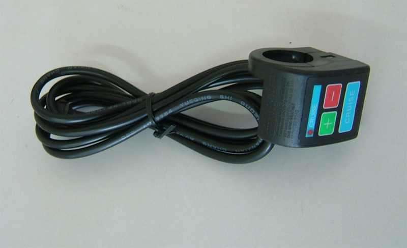
Cruise switch wires
View attachment 2
How does the cruise system work? any one got any ideas?
Could probably guess the pedelc system but would like to be assured that I am correct before I do it
Pedal assist is like this
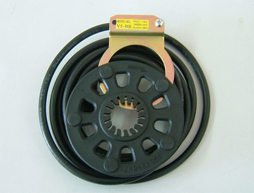
Pins are not in a plug. three of them, yellow, black and red from sensor

Three pins on the controller plug C
Guessing, ground, 5volt and return...Is the pedal sensor a hall effect system? sending out pulses...on the yellow line?
The brake levers are 2 wire on/off switches, but brake connector is 3 wire. I have hydraulic disks now, so will need to make something up, but what are the three wires from brake connector? How is that wired...can e-btakes have a hall system as well? Ground, 5 volt and signal?
I have 3 extra plugs. B, C, D But they do not match what I have on brakes, pedelec or cruise
The cruise plug on the controller is B above...4 pin on 5 pin connector
Cruise switch
Cruise switch wires
View attachment 2
How does the cruise system work? any one got any ideas?
Could probably guess the pedelc system but would like to be assured that I am correct before I do it
Pedal assist is like this
Pins are not in a plug. three of them, yellow, black and red from sensor
Three pins on the controller plug C
Guessing, ground, 5volt and return...Is the pedal sensor a hall effect system? sending out pulses...on the yellow line?
The brake levers are 2 wire on/off switches, but brake connector is 3 wire. I have hydraulic disks now, so will need to make something up, but what are the three wires from brake connector? How is that wired...can e-btakes have a hall system as well? Ground, 5 volt and signal?
![DSC06577 [800x600].jpg](https://endless-sphere.com/sphere/data/attachments/32/32734-fc2979a072c6c01211ee030082442839.jpg "DSC06577 [800x600].jpg")
![TopSideView [800x600].jpg](https://endless-sphere.com/sphere/data/attachments/32/32735-776cfa2db9ec08ee8397621d591a8981.jpg "TopSideView [800x600].jpg")
![eBrake-Left [800x600].jpg](https://endless-sphere.com/sphere/data/attachments/32/32736-69cc11cd1c51a7364f373ecbf61dd526.jpg "eBrake-Left [800x600].jpg")
