whitepony
10 kW
- Joined
- Feb 19, 2015
- Messages
- 663
cant really abandon endless sphere, even though skateboard builders forum is a lot more crowded and active - been working on a short action board with bindings during my summer vacations - inspired like ever so often by okp! been posting in the skateboard builders forum mostly and Ill write the few days of tinkering down in just one post with 88 (!!!) pictures which has its very own charme. most of my builds so far were always scattered over several pages, this is the first time that a basically complete build is available in just one post! 
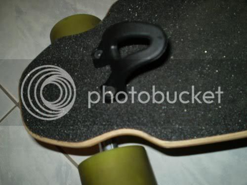
there were a few jet spud builds in the past - torqueboards, runplayback and when I recently came across OKPs unikboard video (http://unikboards.com), I also recognized the jet spud there ... equipped with freeboard S2 bindings woot?!
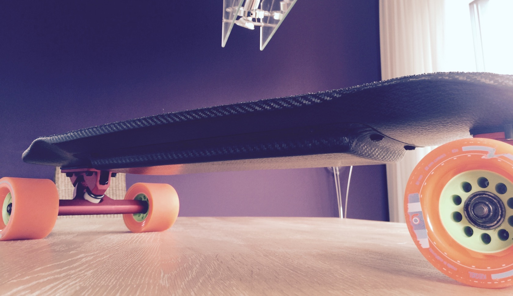
no clue why I didnt think about freeboard bindings on a regular board yet. bindings are an awesome thrill that allows a lot of cool stuff, especially with a board that is probably a lot lighter compared to my trampa. since I had time, I pulled the trigger on the deck, which is pretty cheap with just 85€ incl. shipping and I had plenty of materials left for some carbon fun. the deck is really very interesting - only 29" long, but with comparably large wheelbase and also its fairly wide with a very pronounced concave and wheel wells (it still bites without risers).
this build thread focuses on the infrastructure only, i.e. board, enclosure and battery - think everyone can attach a motor mount and connect the motor to a vesc so much for an intro, lets get to it!
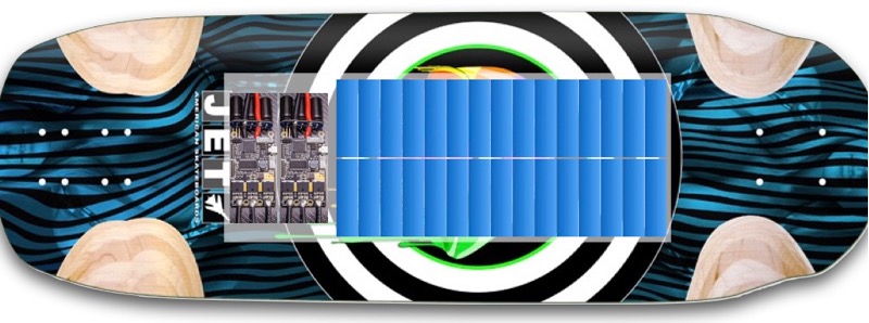
a rough sketch of whats to come: 38x14mm enclosure for 10S3P liion battery and 1 vesc with some electronics:
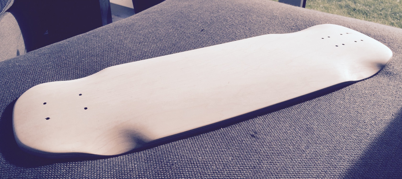
got started with some proper sanding, since I didnt like the overall finish and build quality of the board. wheel wells werent symmetric, the wood under the sketchy graphics was rough, truck mounting holes were larger than what they had to be, but found out quickly why: the drill spots werent very exact and barely fit my testmounted trucks.
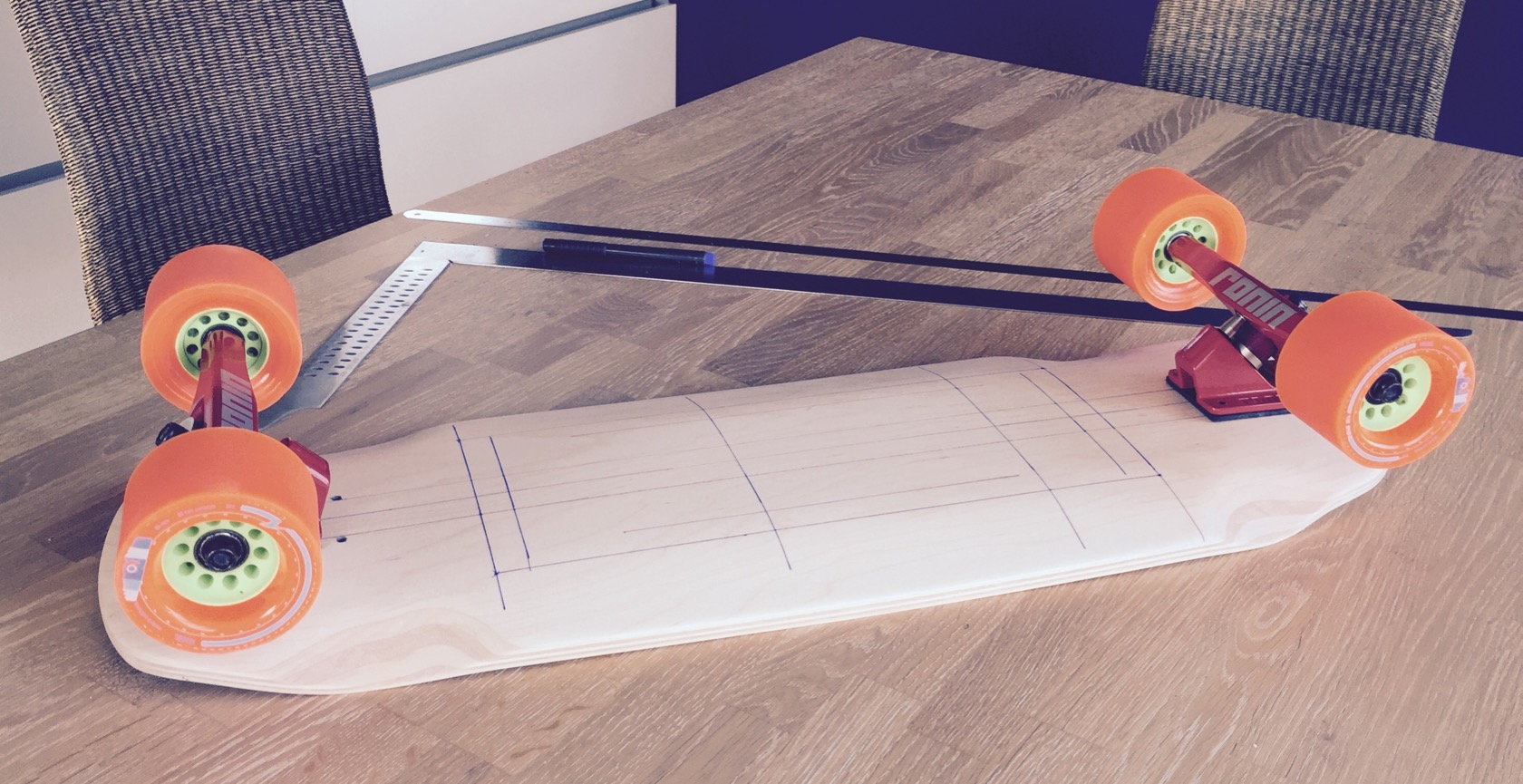
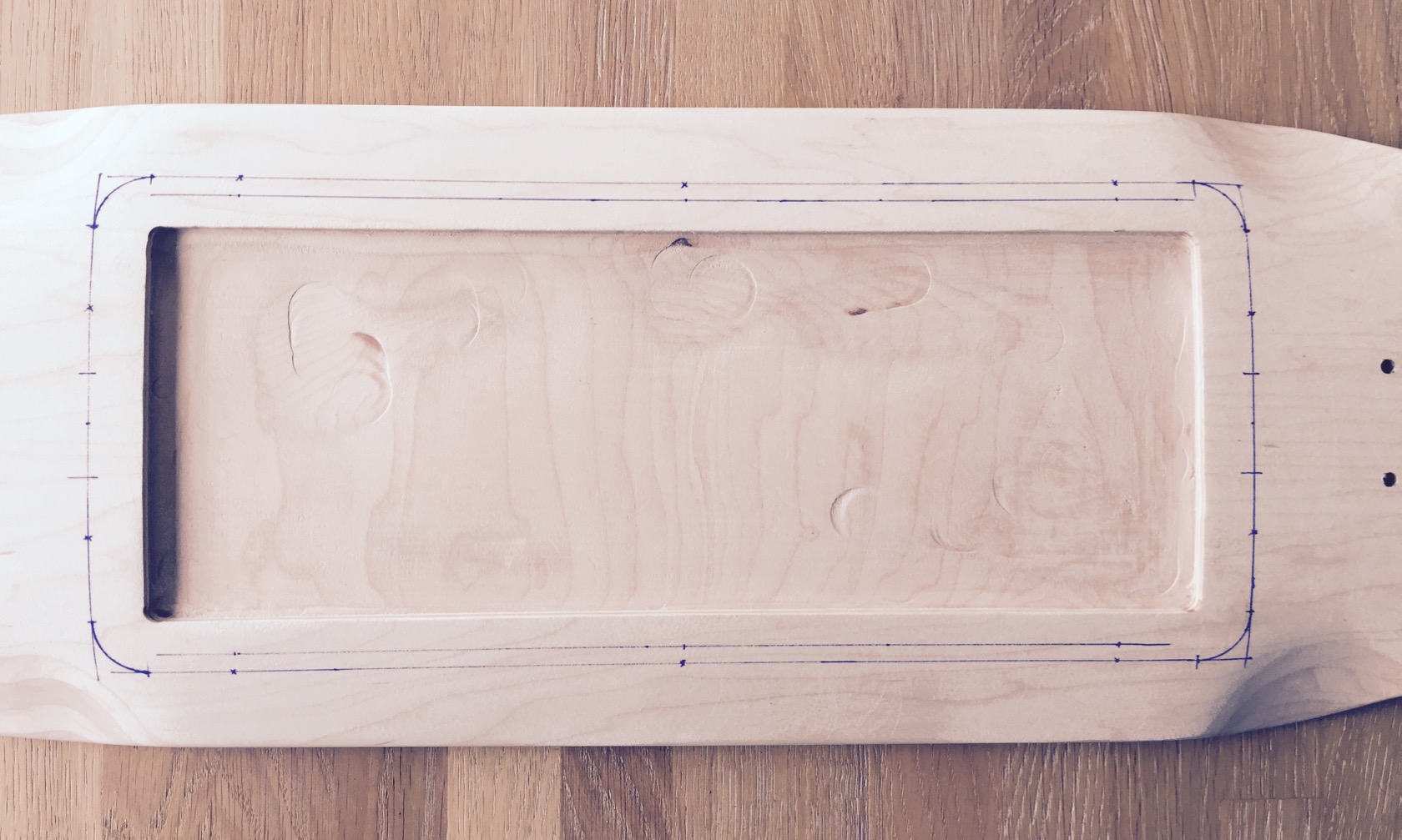
then I started drawing (which works a lot better on wood than on graphics). Had a quick sketch ready on keynote for single vesc and a liion battery and found out quickly, that by taking the wheel wells as enclosure limits, only a 10S3P liion battery was possibly on this board. so far I really loved 10S4P - its a great blend of power and durability. 10S3P will have to work here though, nothing else possible and I think a little less weight probably suits a freeboard well.
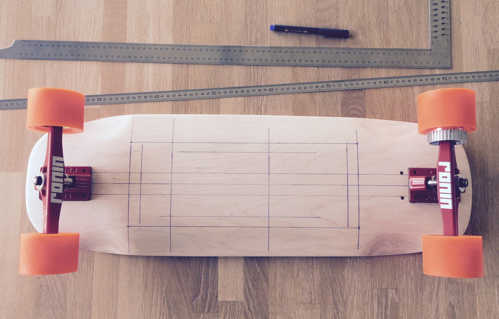
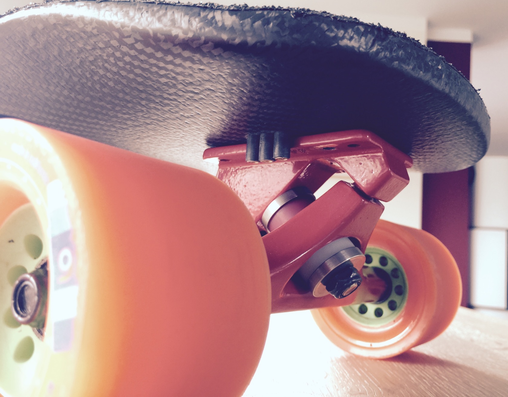
just added the ronins and kegels for some visual impression - got these wheels and trucks since forever in my treasure chest and never got to use them properly. when I tried to downhill the board without motor, I found the ronins too agile though, welt a little scary around 40kph.
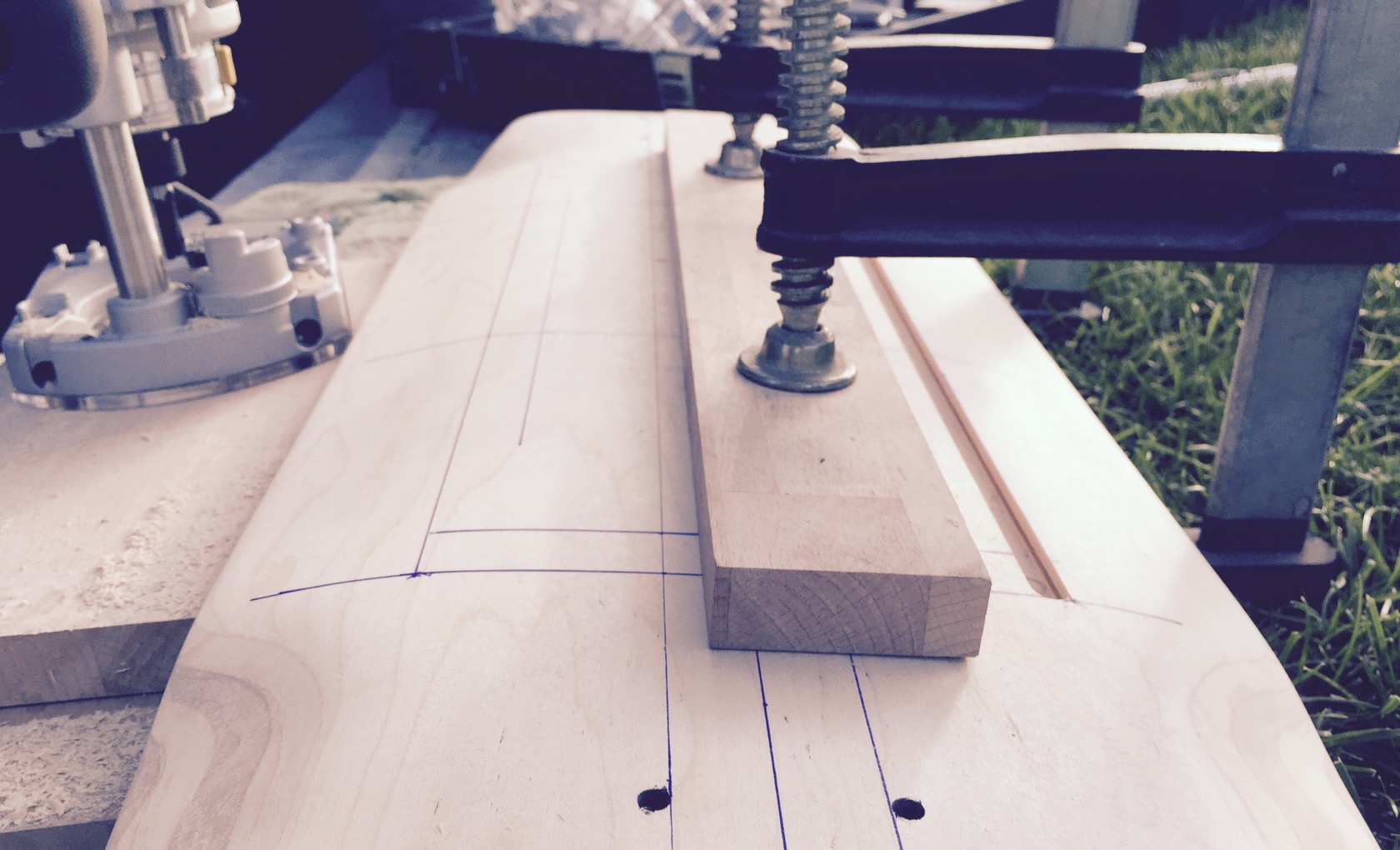
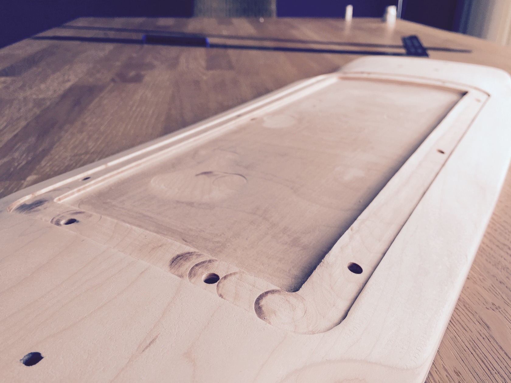
off to routing the electronic compartment - I made some router guide with that straight piece of wood. you can see one routed line there already, nice and straight, much better than free hand routing (which was kinda my first attempt to it a while ago). I carved out wood of 6-7mm depths.
2 long sides done, now the perpendicular sides to have an outline for the rest (which I did with a wider routing bit and without any router guides).
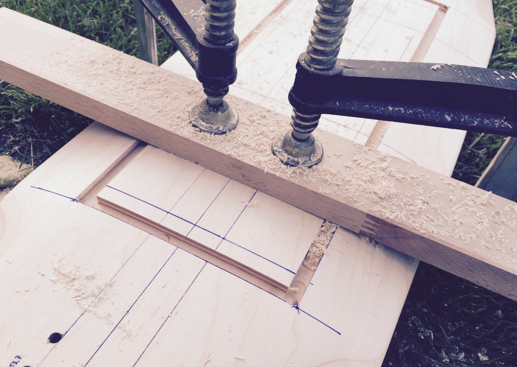
done, some sanding and I called it a good first evening. that 6-7mm depth was REALLY a lot, I think there are just 2-3mm left on the board - sounds really hollow when I knock in the middle region and it feels like I could break the board by hitting the middle hard. gotta need a lot of carbon to restore the structure:
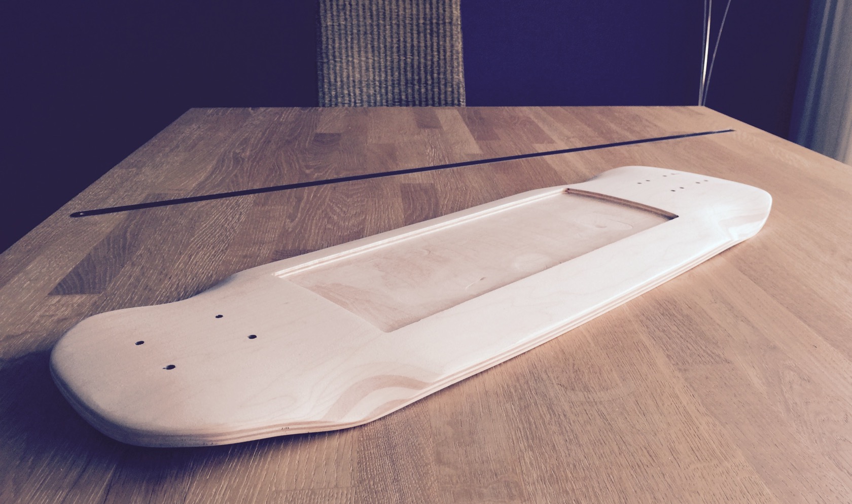
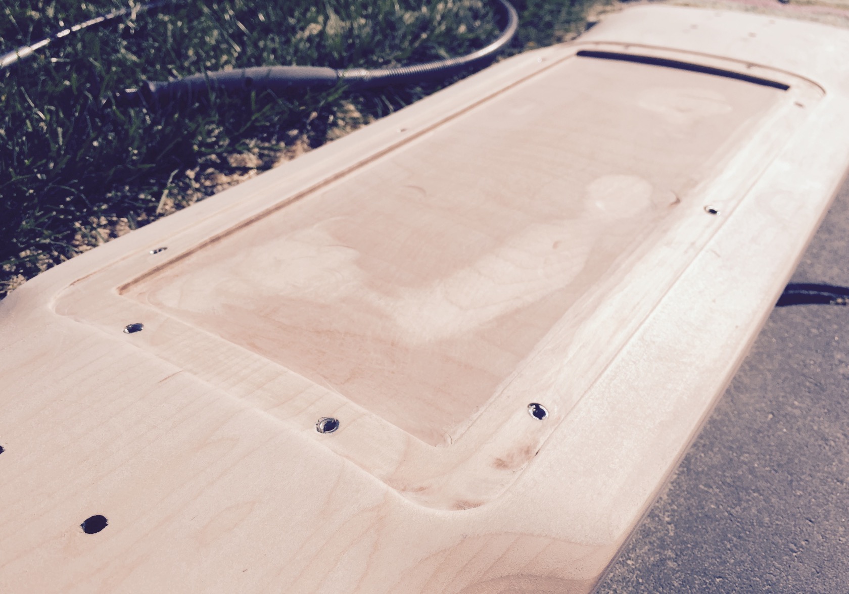
the next day I decided to push things a little further: planned to sink in the enclosure lid like on my evolve board, so that its actually on level ground with the rest of the roadside board surface. this will also make it much easier to trim the enclosure later when its done, since it will act as an automatic trim guide.
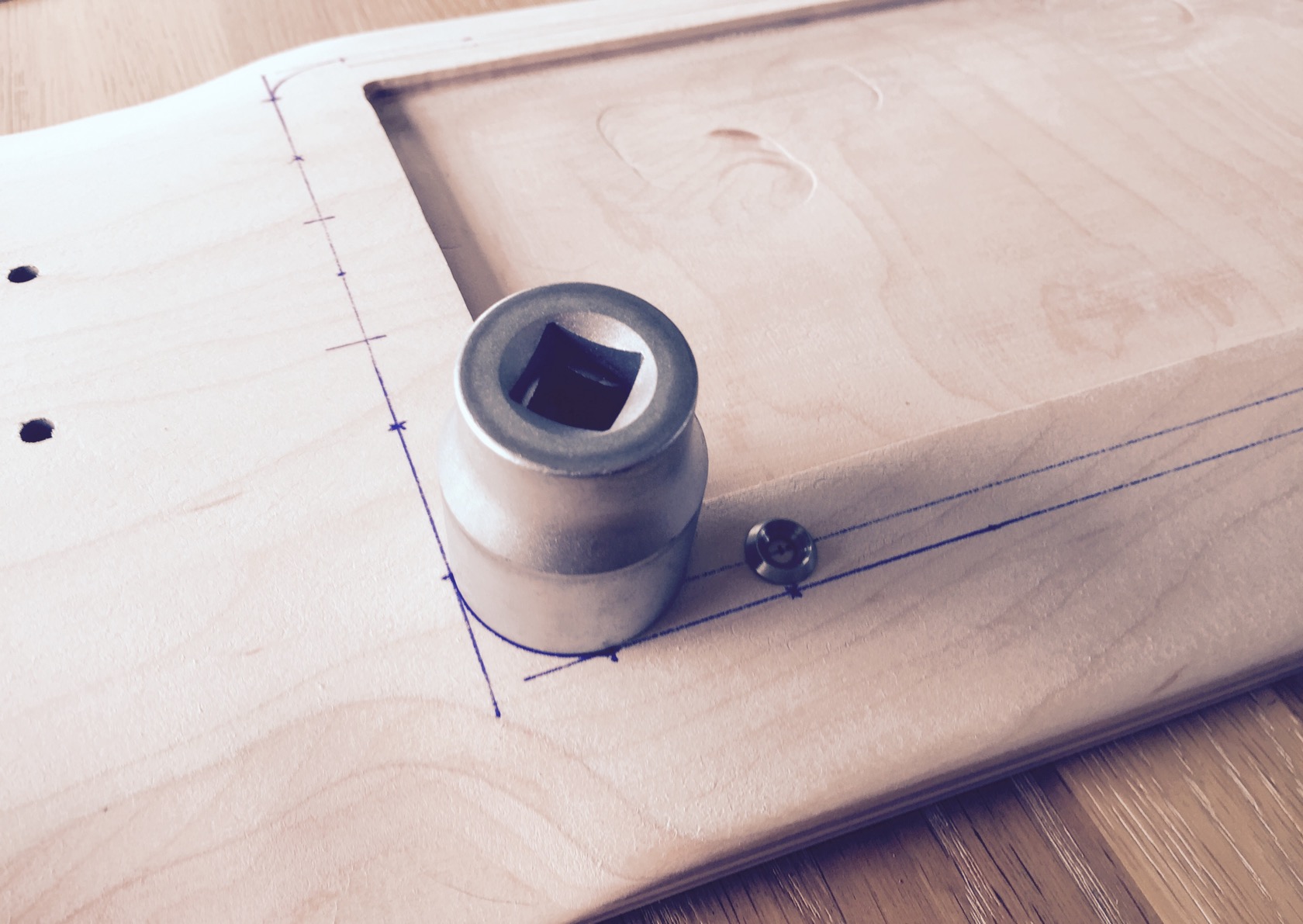
used a large nut for a nice rounded lid:
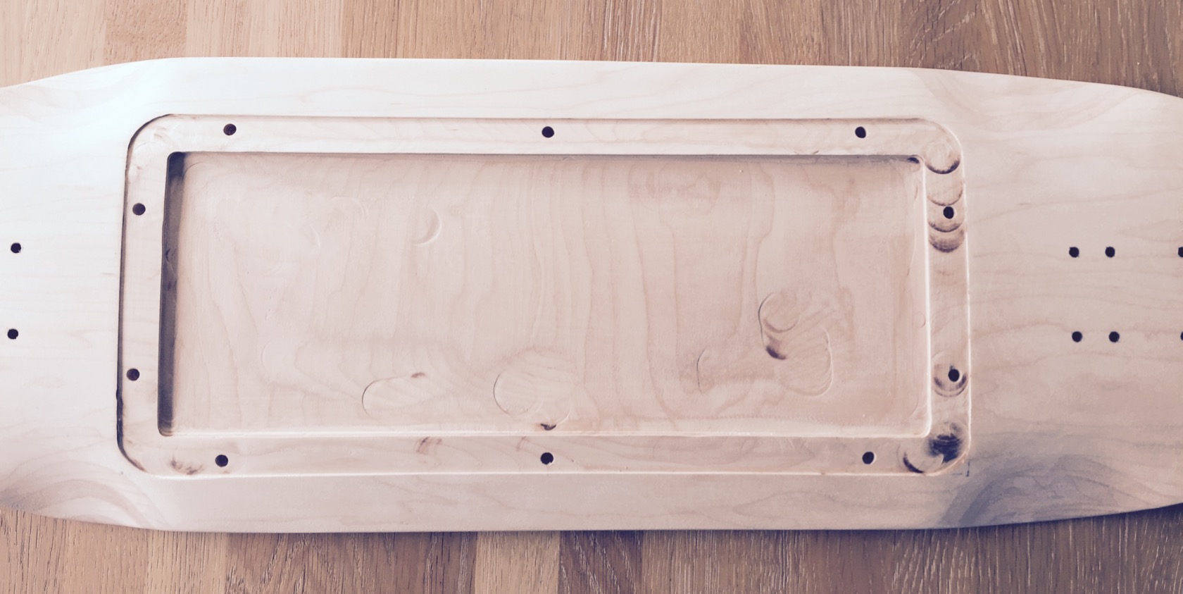
and some routing, I really was extremely careful not to screw it up since, unlike the middle routed box, the sunk in lid will be visible from the outside. I also drilled mounting holes already for M4 inserts, so that those will actually be protected and not visible under the carbon.
few more impressions:
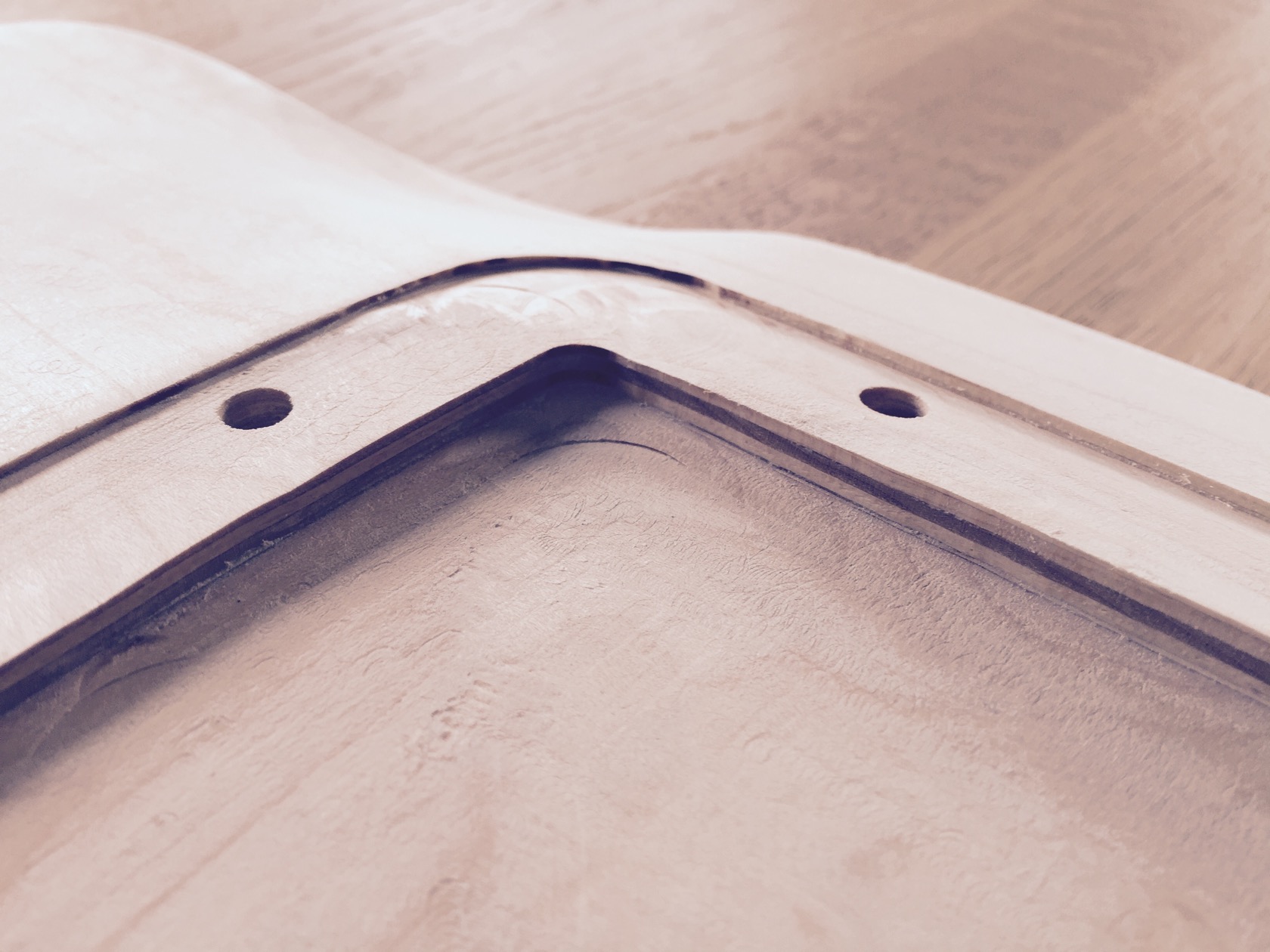
had some burn marks from the router bit because I was very careful and worked very slowly
added the m4 inserts ...
... and used filler to get rid of the 2nd pair of mounting truck holes and some imperfections.
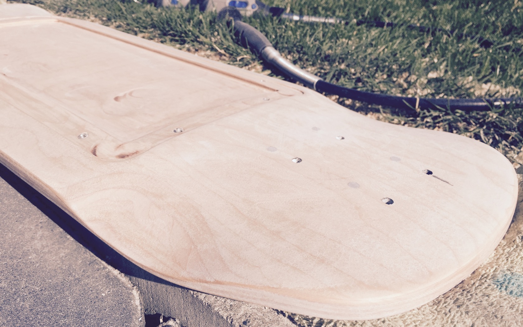
I actually drilled real holes into the board this time for the inserts. my plan is to lay a few layers of carbon roadside to restore the boards structure, then use a very slim drill bit to open the carbon in the right places from the boards topside! the carbon and resin will keep the inserts in place nicely and the inserts will be actually mostly covered by carbon except for the small m4 hole!
problem is with these inserts: sometimes, and only when used with loctite, the inserted threads will come out - set under carbon and resin like that, it certainly wont happen. topside of the board will get the same treatment later, so the inserts will be stuck between 2 resin carbon sheets and that should properly seat them for good!
anyway, to actually lay carbon, I didnt want the resin to fill the threads of the m4 inserts and exit on board top side, so I added m4 screws into the inserts. Im a little worried about that, not sure how strong the resin bond will be.
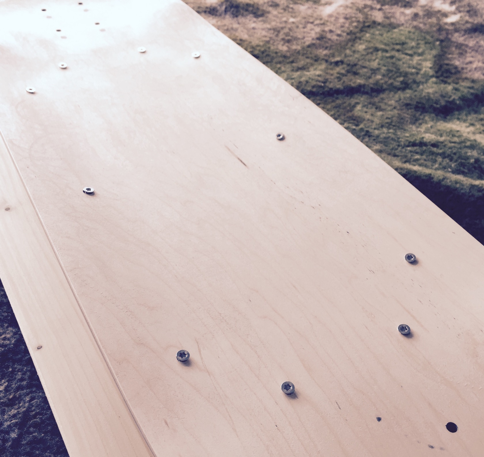
threads are covered! quick note here before Im off to vacuum bagging: on all pictures you can see that the surface isnt actually supersmooth, but sanded with quite rough grid (P40). I did that on purpose to allow a the strongest bond between maple <-> resin & carbon layers!
preparations for vacuum bagging: starting with the last things first and then working my way from the top when the resin is set up: vacuum bag prepared, the soaking breather layer, that also allows the vacuum pump to reach every spot evenly cut into the right format!
bleeder layer - basically a release film with small holes in it, so resin can transfer through to be soaked by the breather layer:
nice air grade carbon twill for a sexy finish:
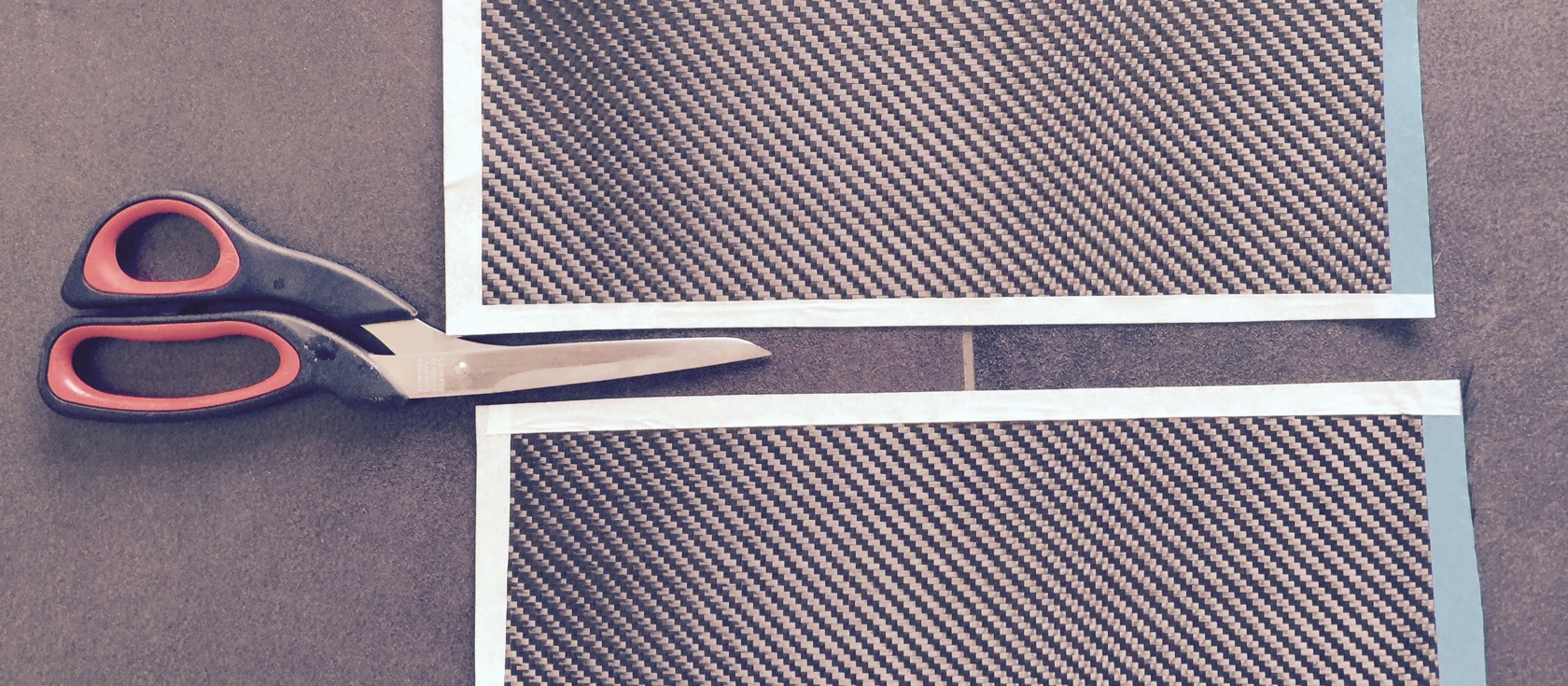
a small tip: when you cut carbon or glas weave, take some painters tape and tape the outline directly on the carbon, then cut right through it! like that you wont have fibers flying around all over the place and the carbon wont fray on the edge:
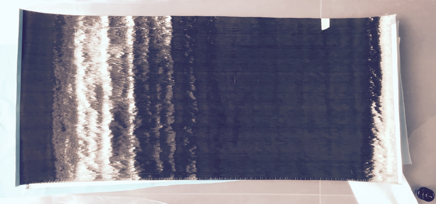
last thing and basically first layer when I start the layup: unidirectional carbon to max the strength of the typical skateboard load (bending towards road between the trucks).
the layup will be 1x unidirectional carbon (which is a little stiffer to work with and 2x carbon twill, then add the bleeder, then breather, then put it into the vacuum bag and switch on the pump. I really dont think 3 layers is enough to fully restore the boards structure, but Ill add one more gfk + carbon layer ontop to cover LHB-style motor wires (more if I feel like I need it - will do a careful load test after the 3 current roadside layers have cured).
sadly no pictures of the layup - couldnt take any with soggy resin hands and I try to work swiftly because the resin keeps curing.
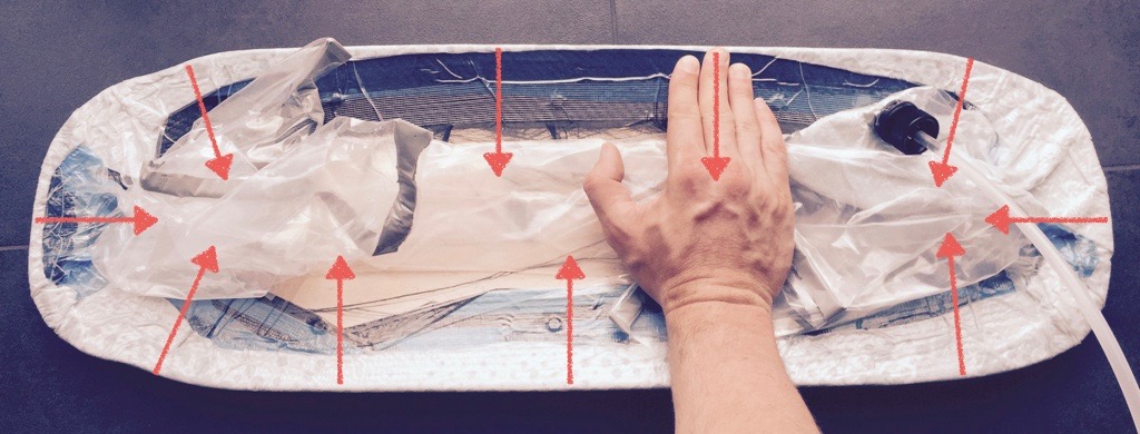
when I switched on the pump, I used the vacuum bag and the increasing pressure of the bag on the board to smoothly wrap the carbon all around the edges (hard to explain - usually a vacuum bag wouldnt put pressure on the edges really - or straighten them out or wrap around the board). this time I wanted the boardedges covered with carbon - for looks, but mostly to add further structural support and its not THAT trivial to actually get a tight fit and pressure around the edges of the board. I drew a picture to explain it - basically, with rubber gloves on my hands, I pulled the bag towards the middle on topside with really a lot of force while the pump kept applying more and more pressure on the bag.
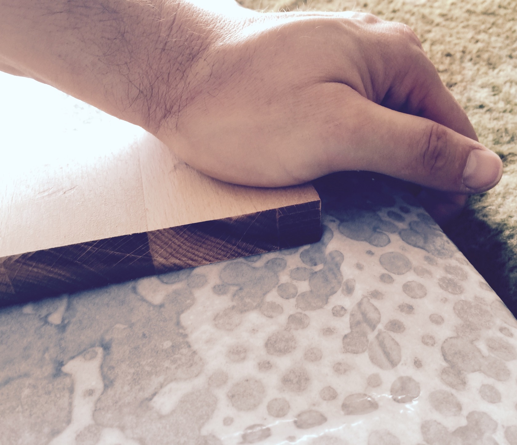
ontop of that I also used a pretty sharp edged wood block to stretch the vacuum bag in the right spots so that the routed electric compartment will have sharp edges. if you dont do that, the edges will be very rounded, with air or resin below the carbon weave and youll lose a lot of your enclosure surface by that.
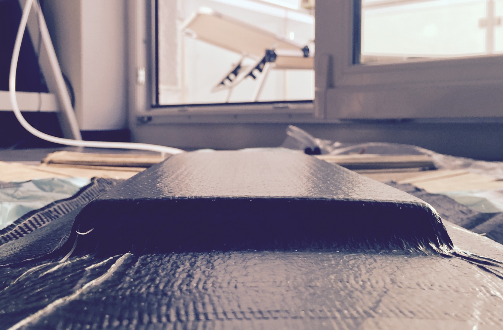
fairly sharp contours - this will be one of my sharpest vacuum bagging features on a board so far I think.
here you can see the roadside result of how I wrapped the vacuum bag around the board:
thats it for now - time to clean up and wait for the resin to cure (24h).
________________________
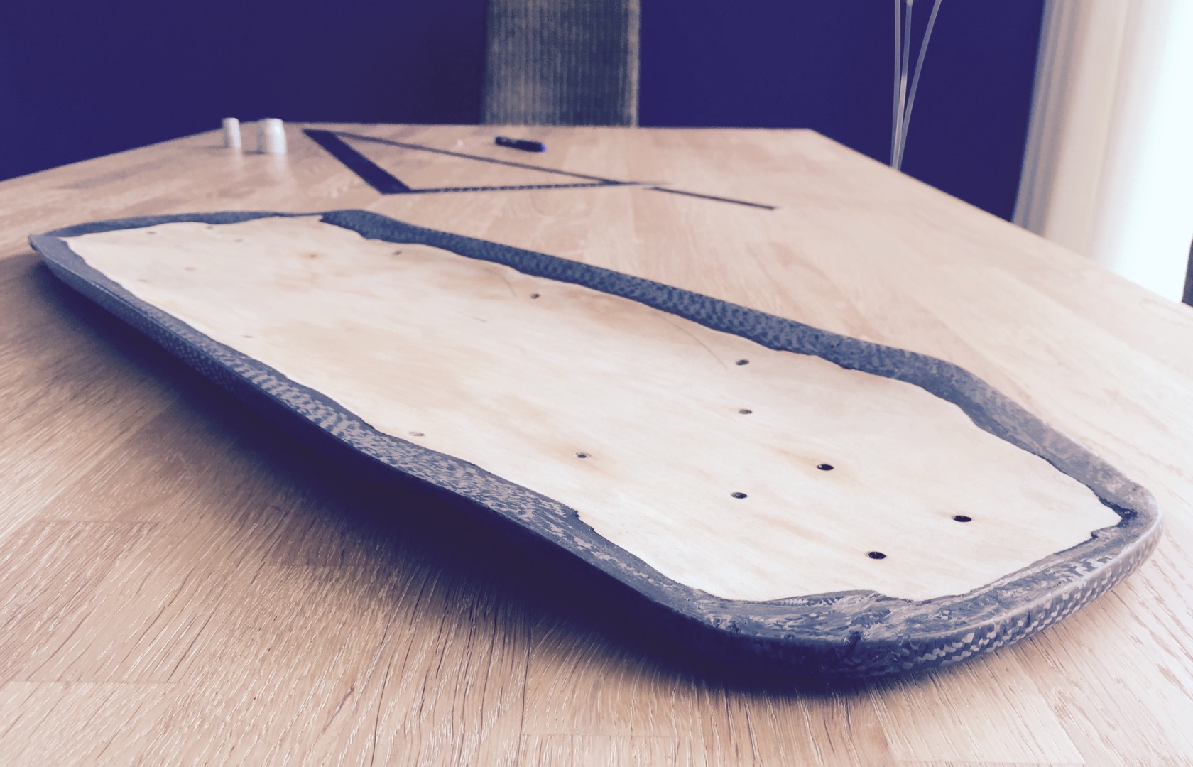
I already noticed when I left the board for curing that the wrapping of the carbon around the board will leave a mess on topside. partly the screws were covered, resin soaked weave everywhere and it wasnt always just flat, but crumbled. long story short: topside WAS a resin crusted mess.
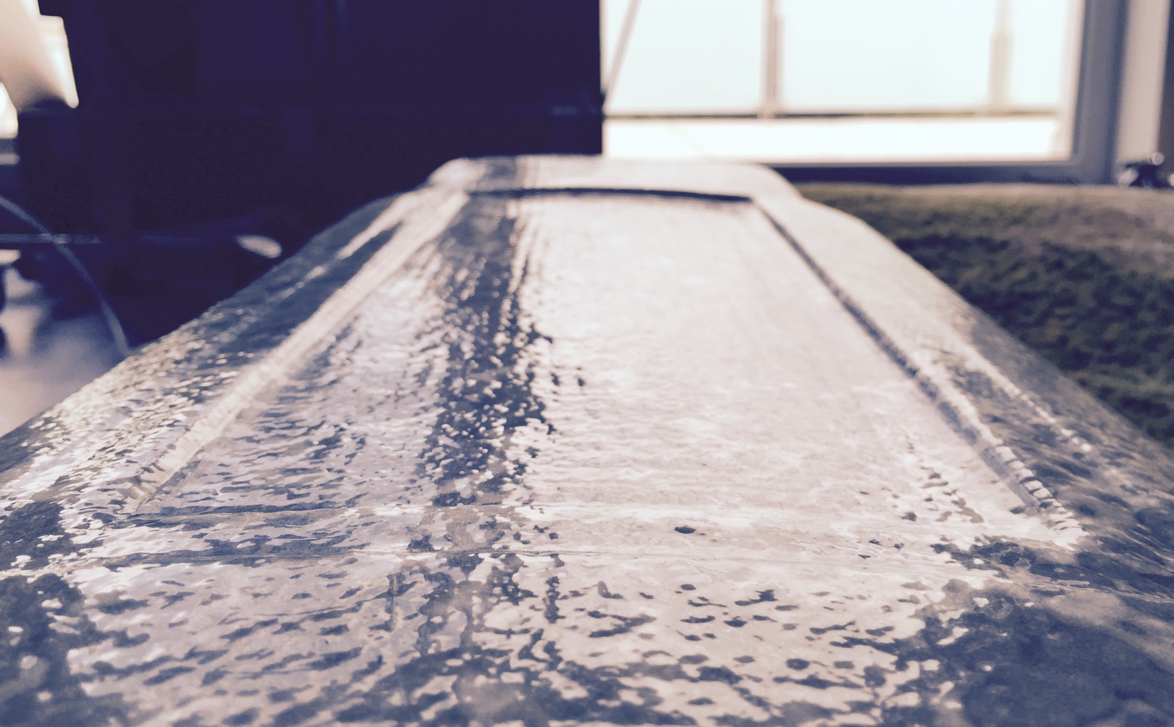
but lets start with the good things! thats how the roadside came out - no sanding, nothing, just removed the breather and bleeder layer.
you can tell its fresh from the vacuum bag from the small white pimples on the carbon. these are the tiny holes of the bleeder layer, where the breather layer gets stuck a little bit.
ok, turning it around ... argh this would be a mess for sanding, since from sanding heat, the resin becomes fluid again and then it clogs up your sand paper instantly. also I was super afraid of the screws - looked like the resin actually found its way through the inserted threads and came out on topside, seating the screws nicely.
but I mean, at least the board edges are well covered by the carbon - looking good overall except for the topside mess.
alright then, my favourite hobby: sanding in the burning midday heat with 50% humidity and a dust mask against the carbon dust.
more or less done - the rest is cosmetic litte stuff Ill do before I lay another gfk/carbon layer after motor wire channels. thank god the screws came out and the inserts stayed - I used special screws with a large torx head so that I really could grab them with some torque without killing off the head. all of them came lose after instant full torque with the cordless electric screwdriver and at least the inserts appear to be really strongly bonded with the wood resin and carbon.
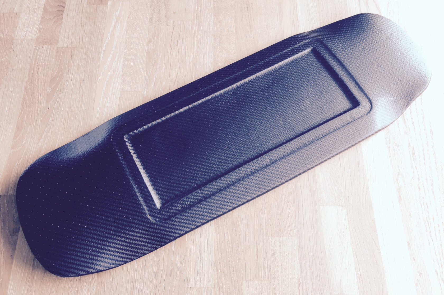
rest of the board has turned out nicely. pimples gone, sanded under water with 280, then 600 grit.
and 2 more perspectives
__________
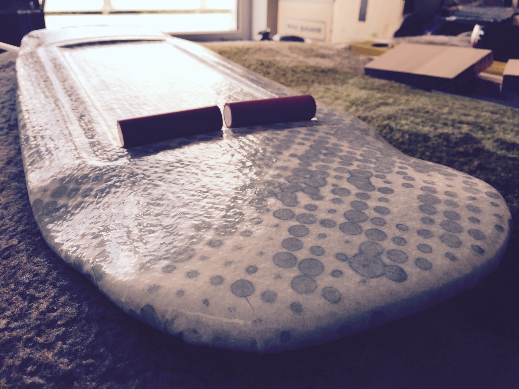
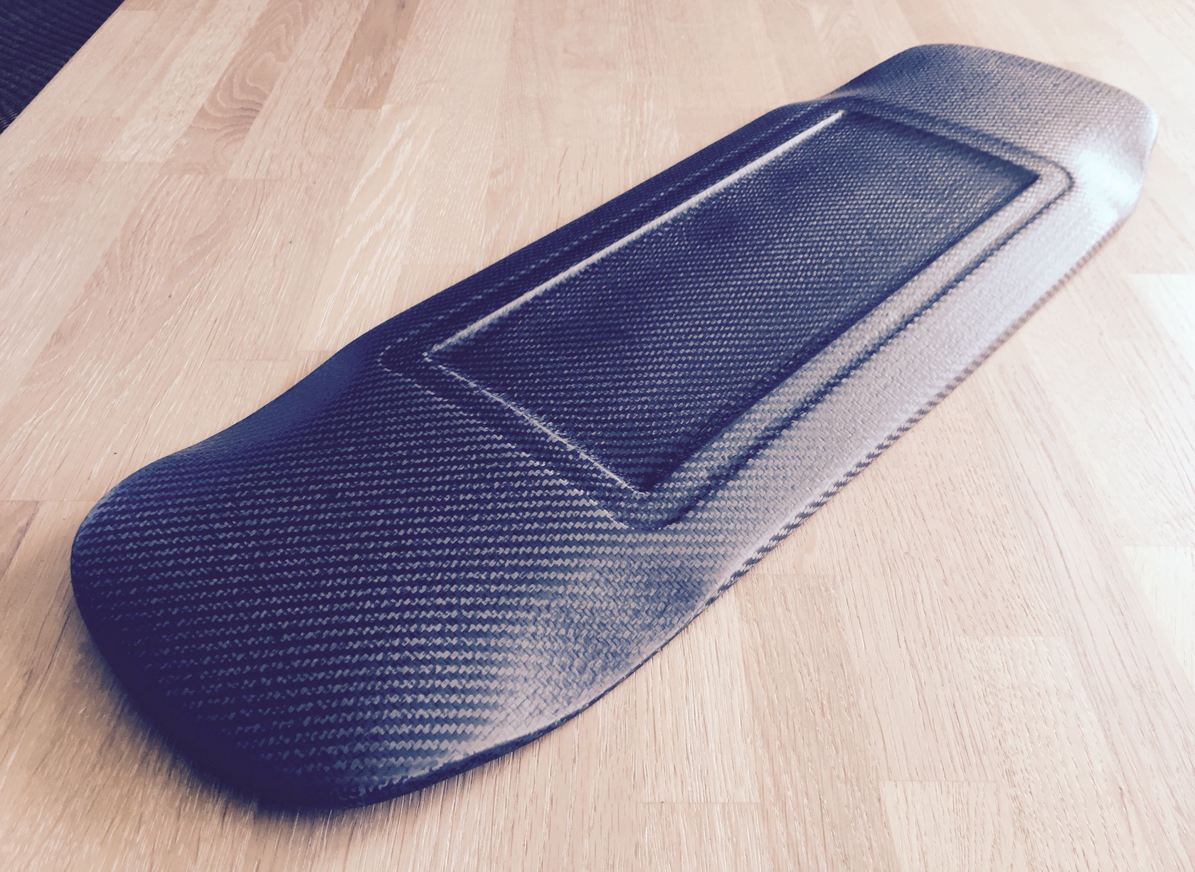
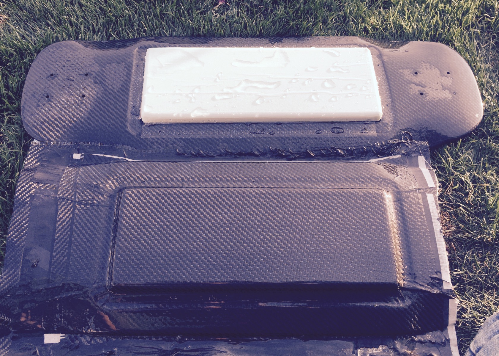
the same evening I started with the enclosure made by a foam mold from 30kg/m^3 XPS foam thats supposed to be a little more rigid than my bad other foam experiences where the foam gave in under the pressure. against all odds and a clearly visible dent through 2 layers of breather, the enclosure came out great!!
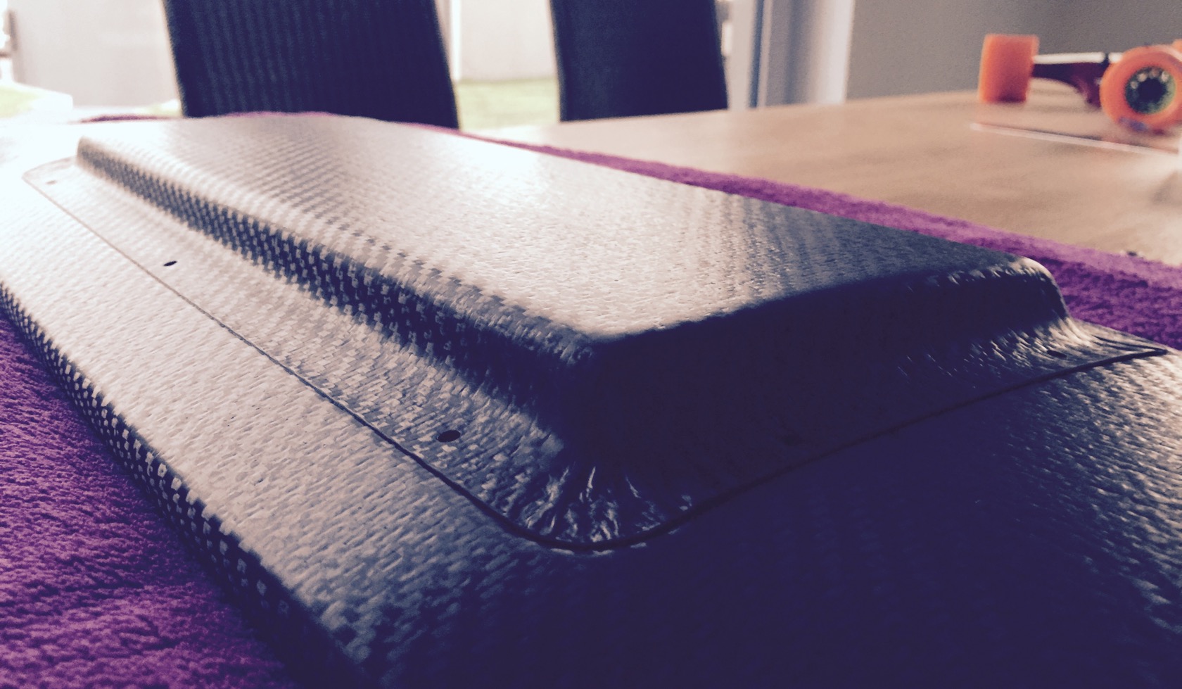
very smooth top
nice and evenly rounded edges
usually you have these crumbled edges where the bleeder foil is crumbled. no idea how to get around that. its easy enough to sand though!
and a slight concave following the routed compartment. thats the cool part of the hard foam mold - it follows light curvatures just from the vacuum pressure!
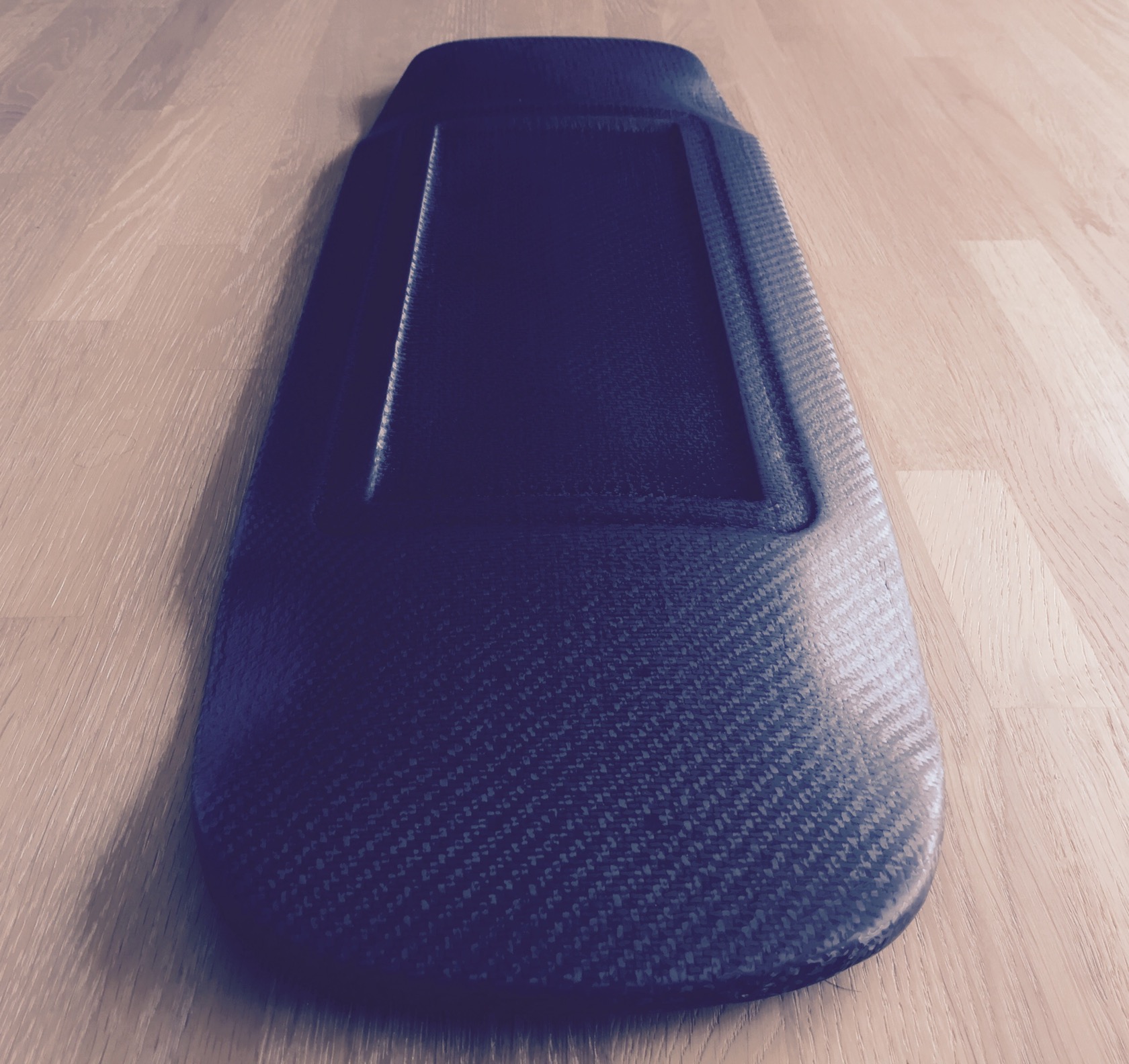
back from cutting, sanding and drilling holes! it was a little dark already, couldnt take any nice pictures with sunlight on the carbon texture anymore ... but got a few impressions at least.
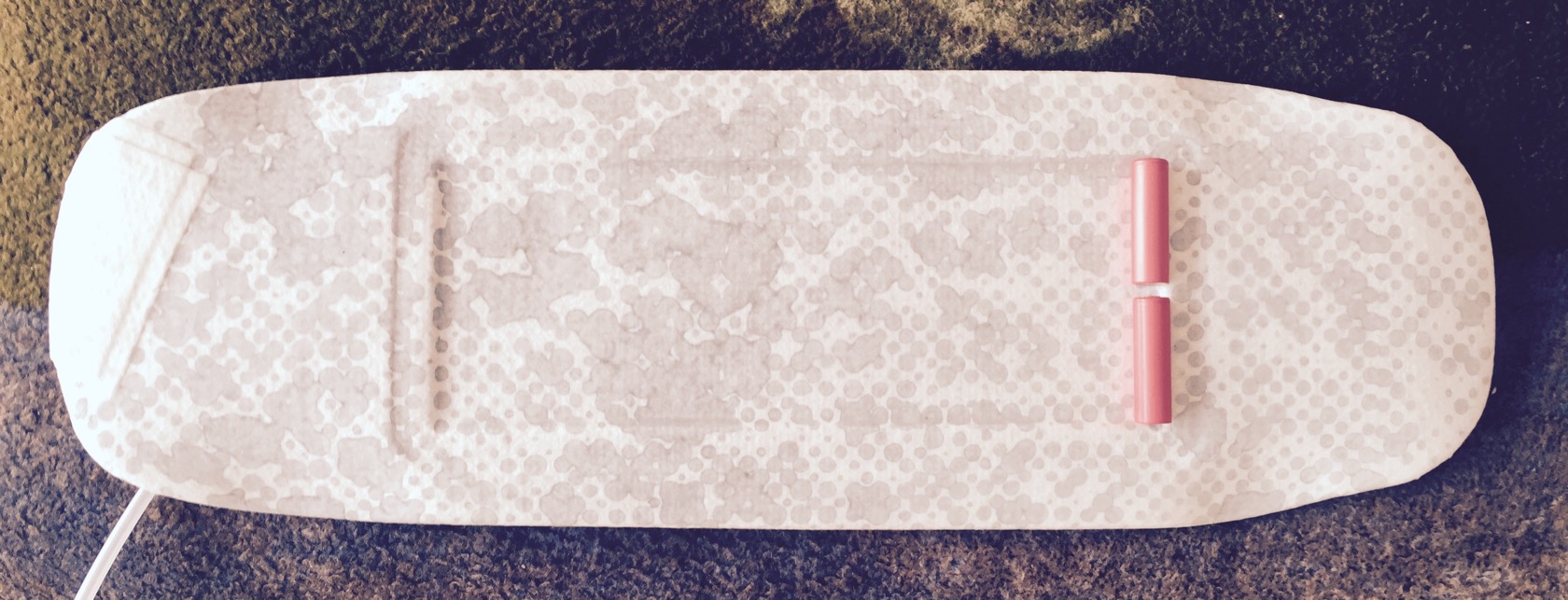
starting with drilling holes from the boards topside right through the boards roadside carbon layers and the enclosure lid with a 3mm drill bit that wouldnt hurt the M4 threads of the inserts. you can spot the tiny holes if you look closely! I left the foam mold on the board so you can have a look at it - its very simple, all I did was cutting a correctly sized rectangle from a larger industrial XPS foam plate and rounding the edges a little. note how I also rounded the boardside edges because of the rounded edges of the carbon compartment in the board - the vacuum bag will pull the foam down to the ground of the compartment and bend it smoothly around the mild concave - but for that to happen the foam piece had to be a perfect fit for the rounded carbon ground!
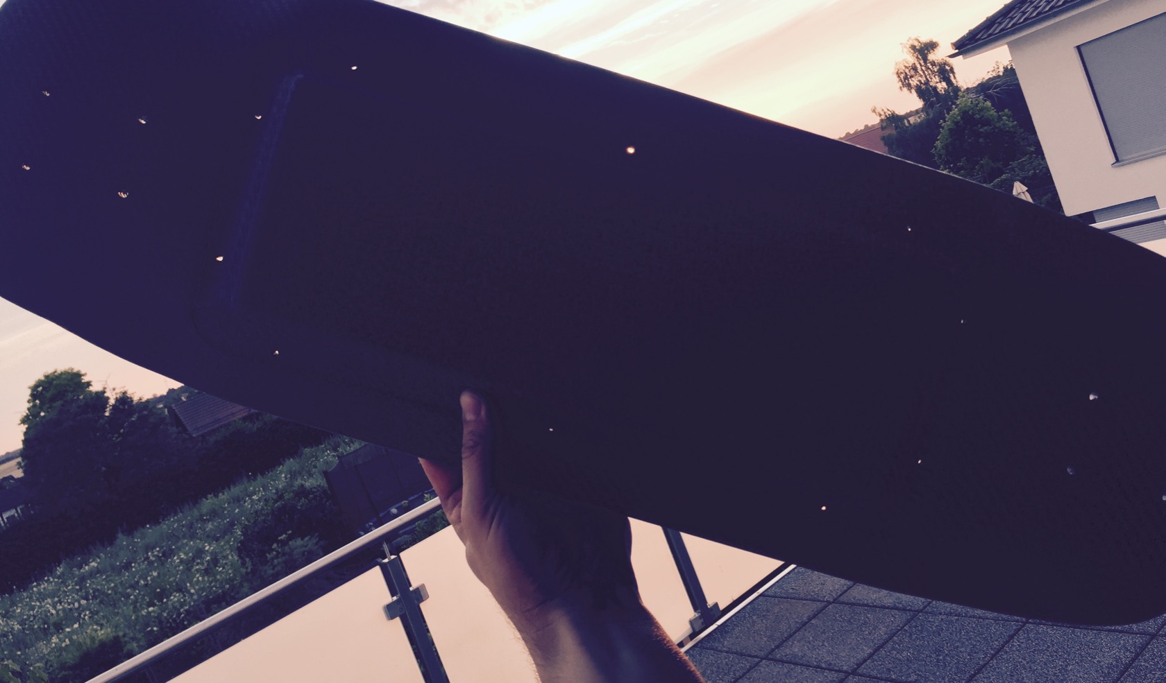
frock yea, you can see right through all 10 holes WITH the enclosure attached!
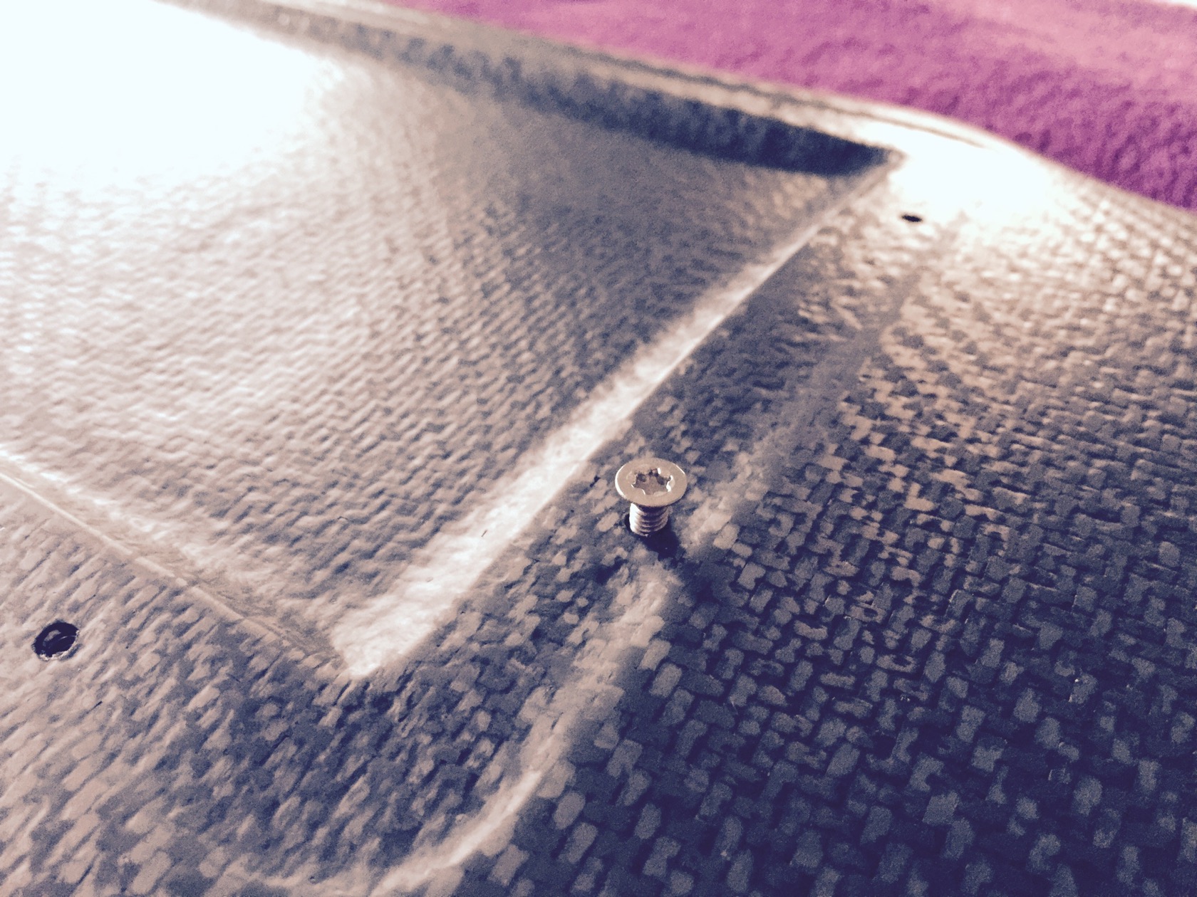
and the m4 inserts are perfectly hidden under the carbon:
enclosure is a nice fit, it actually sticked to the board from the adhesive effect of water alone
transition board surface <-> enclosure is ok, I couldve cut the lid a little slimmer, but didnt want to cut too much around the drilled holes.
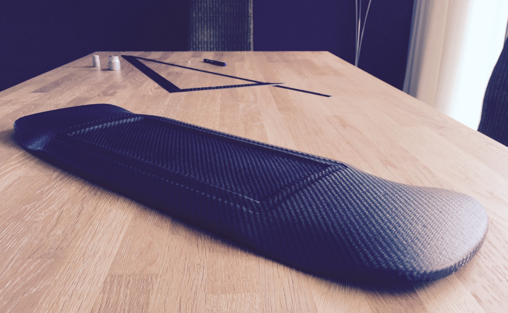
note how the texture of the enclosure carbon perfectly transitions into the texture of the board carbon 8)
its really slim
___________________
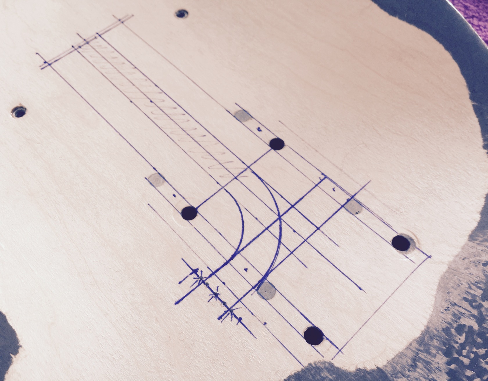
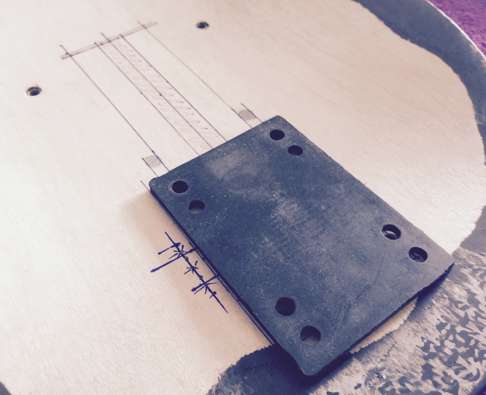
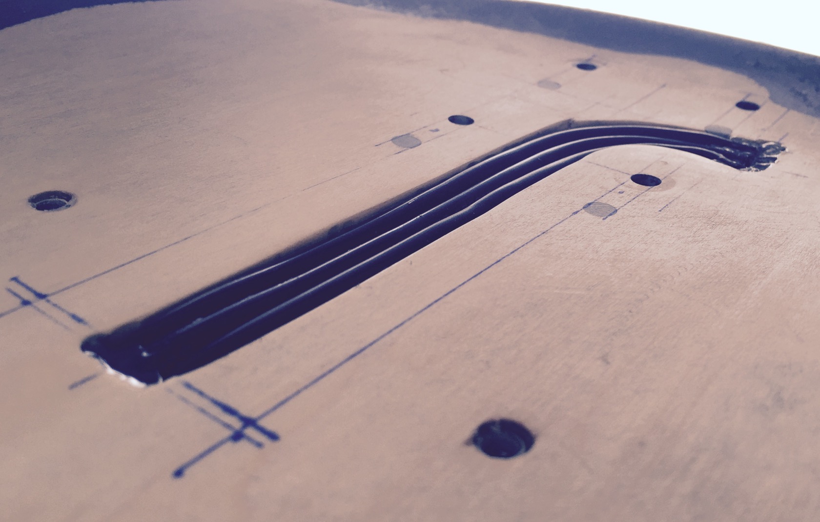
finally working on the motor wire channels on the boards top side. started with drawing - this time no silly rectangular shapes but something that the 3 parallel wires can actually follow:
exiting right next to typical rubber pads, which are a little wider than most truck baseplates:
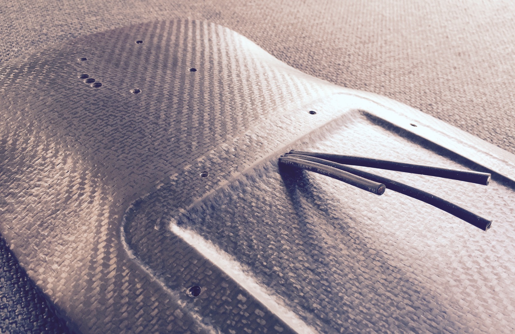
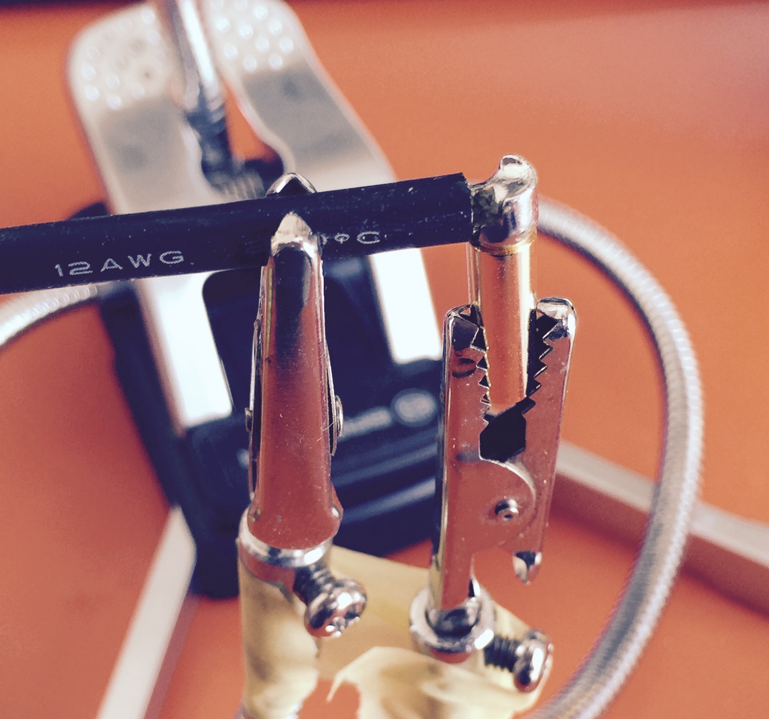
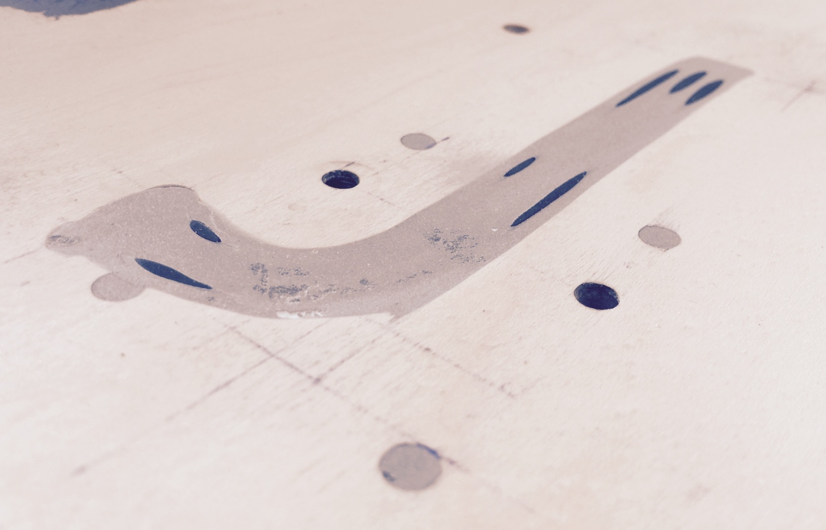
routing, this time by hand since the geometry and the router base plate didnt allow to go with reasonable guides. it was quite messy, because with the big router baseplate, I routed a lot of different and varying depths, so I had to adjust height frequently, reroute, repeat. a little annoying and not very surgical like my electronic compartment. but it works and wont be visible anyway, 3x 12AWG wires in!
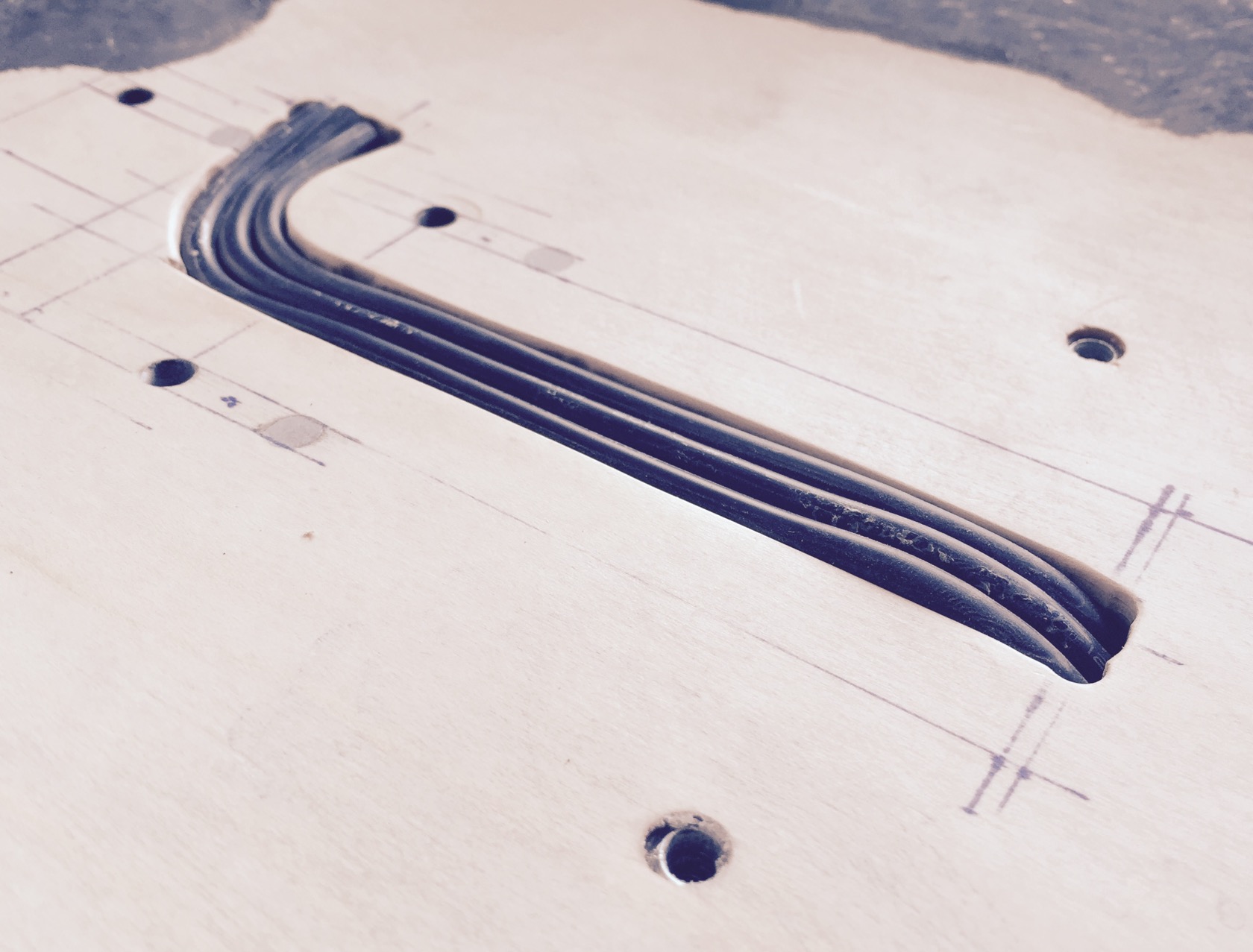
and they exit directly in the electronic compartment:
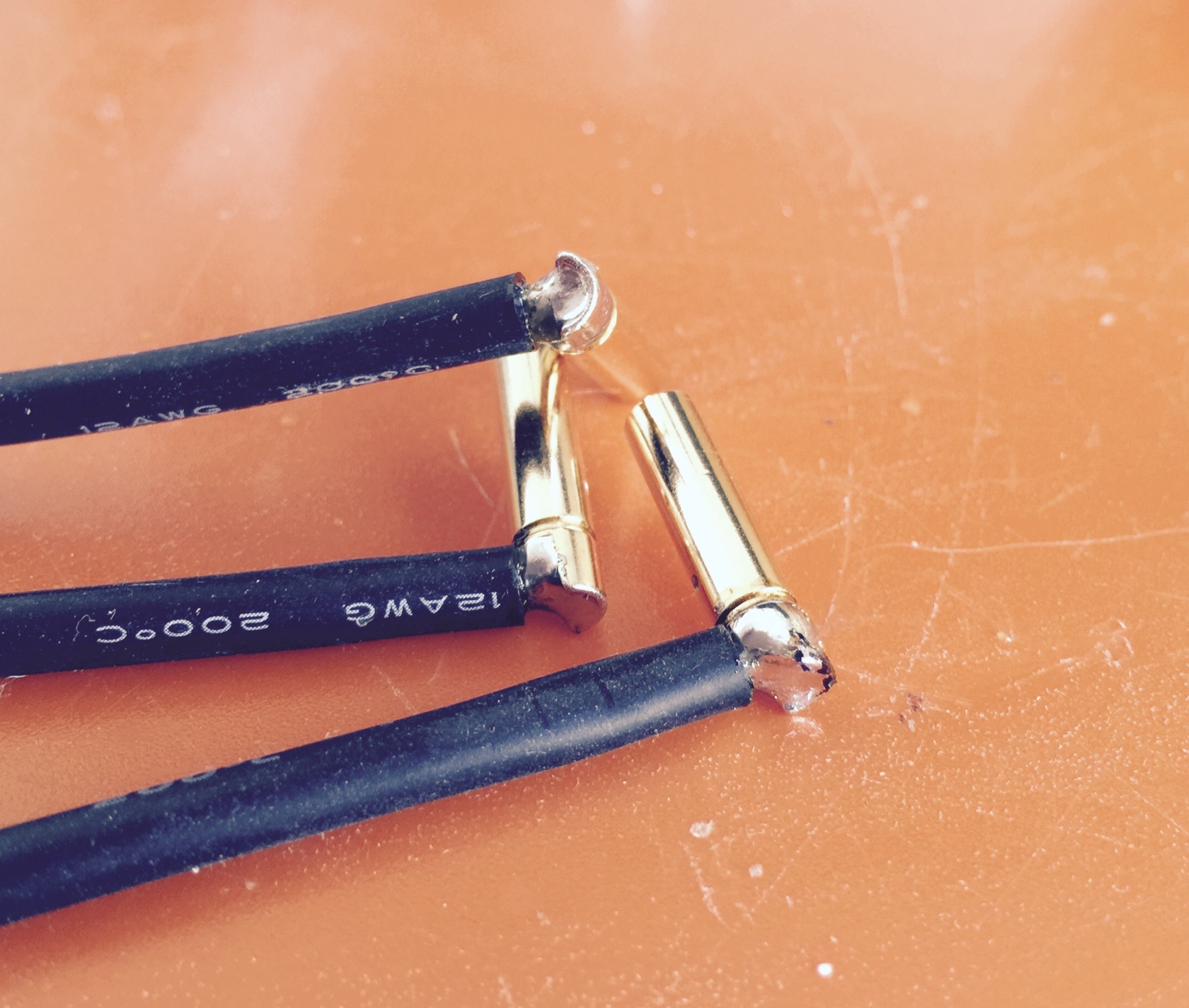
my useful little helper for the 90° bullet connector insert:
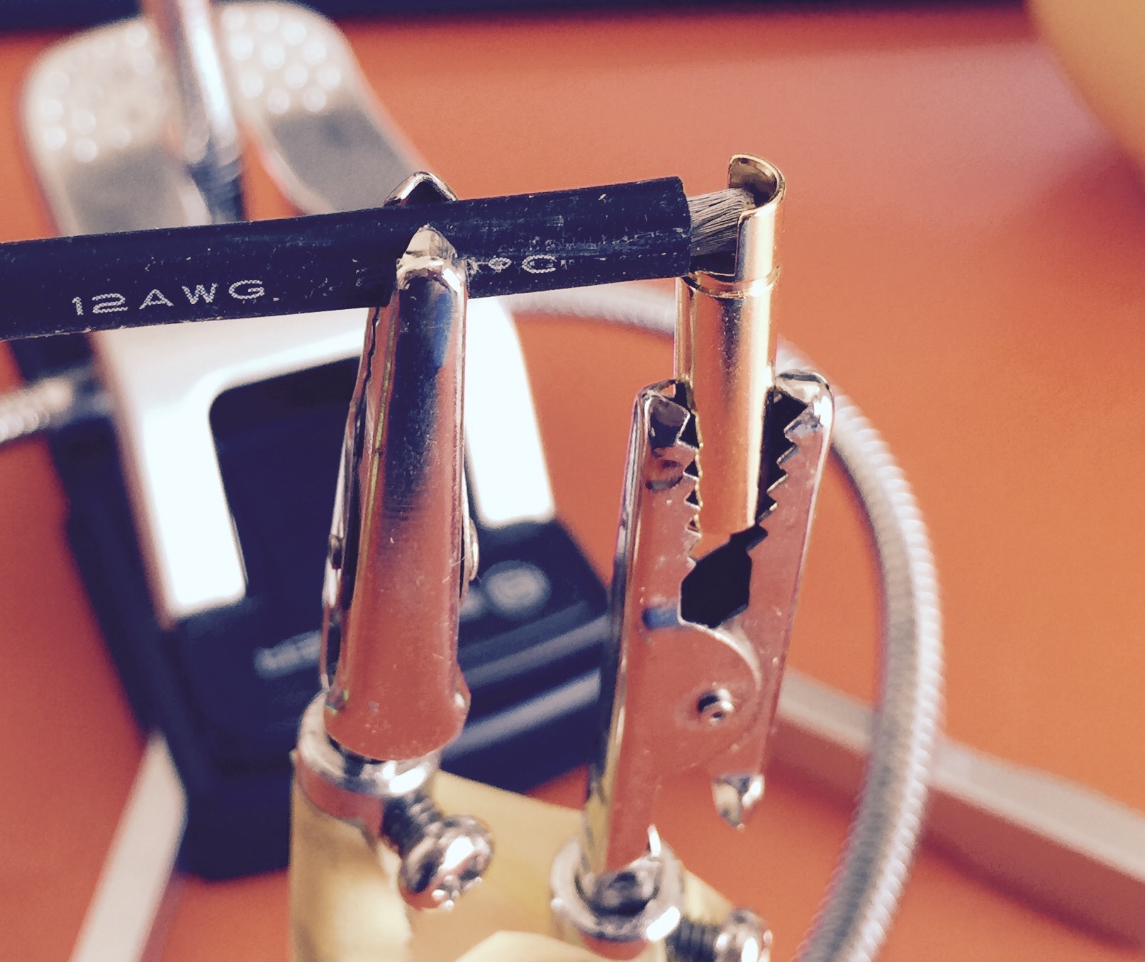
really a lot of tin and allowing it to sink in really deep
3 wires done, now off to heat shrink
got very thick shrink tube with glue inside, because I dont want them to short the motor phases via the carbon roadside. this shrink tube is really super sturdy!!
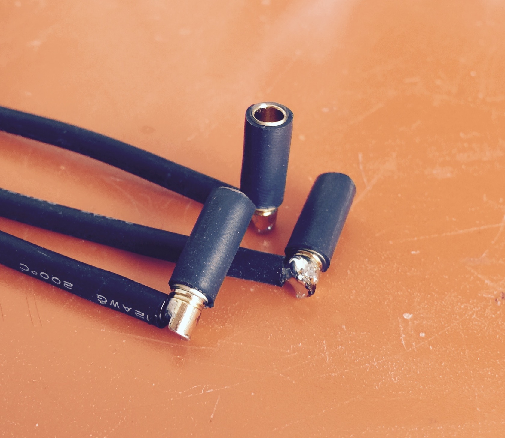
hammered them in (6.5mm drilled holes just barely fit, I really cant remove or stick them in further with my hands, had to use the hammer
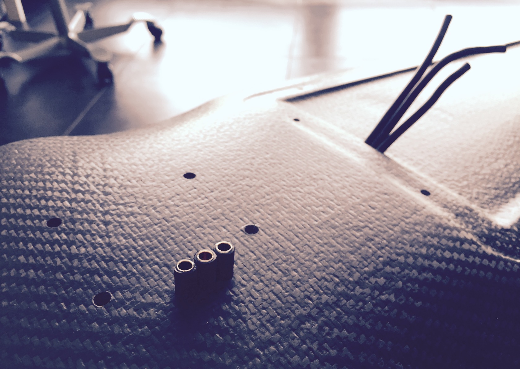
glued the wires to the wood and closed the exits with glue too
this time no resin mess, just used putty to level it out. Im not sure if this will stay intact, but Ill try. really didnt feel like resin, gfk, vacuum bag, wait for another 24h, screw up the roadside carbon finish, because resin somehow always finds a way to make a mess...
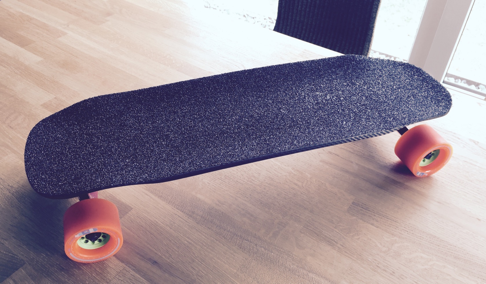
apply vicious grip and we are basically done here for now:
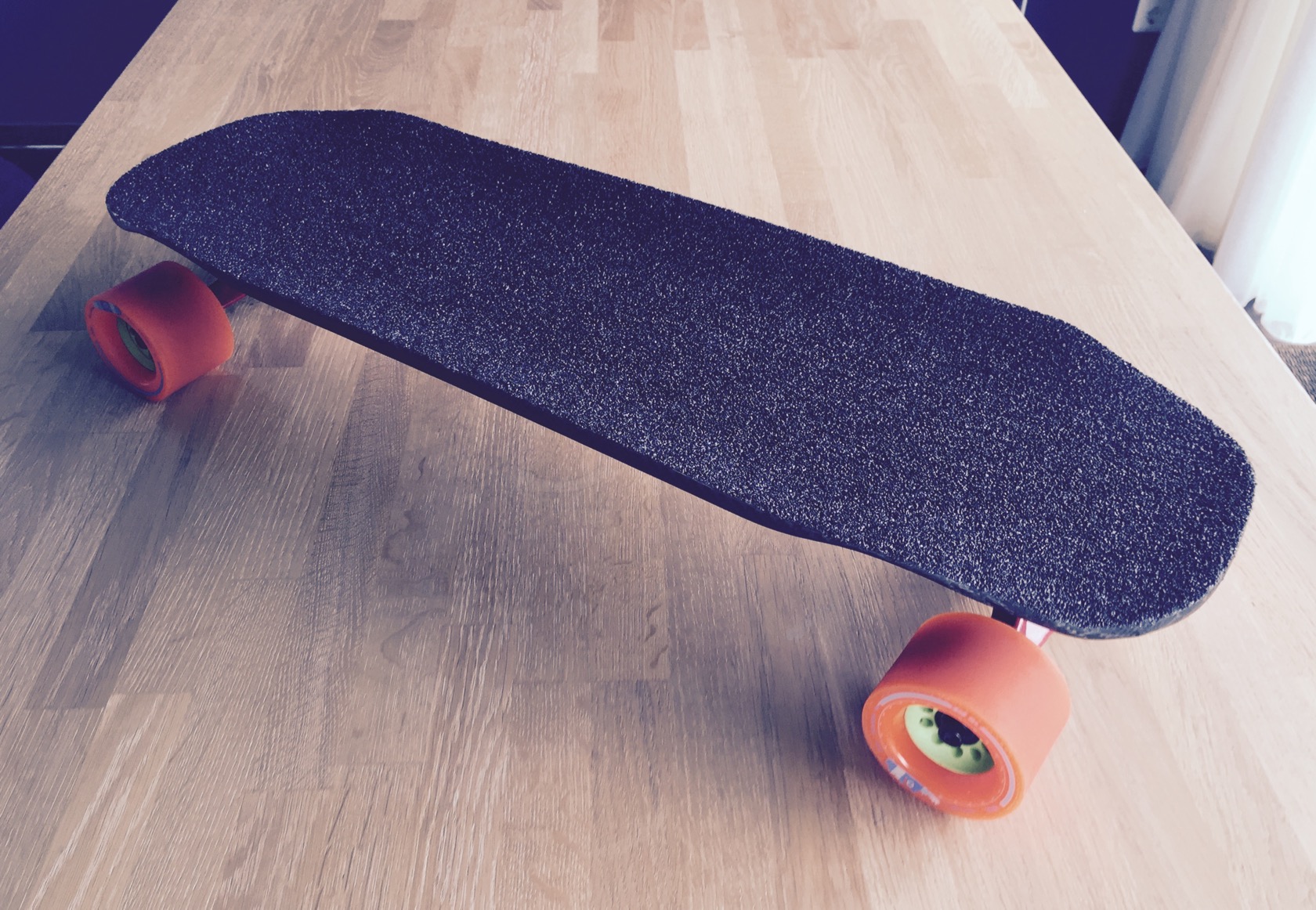
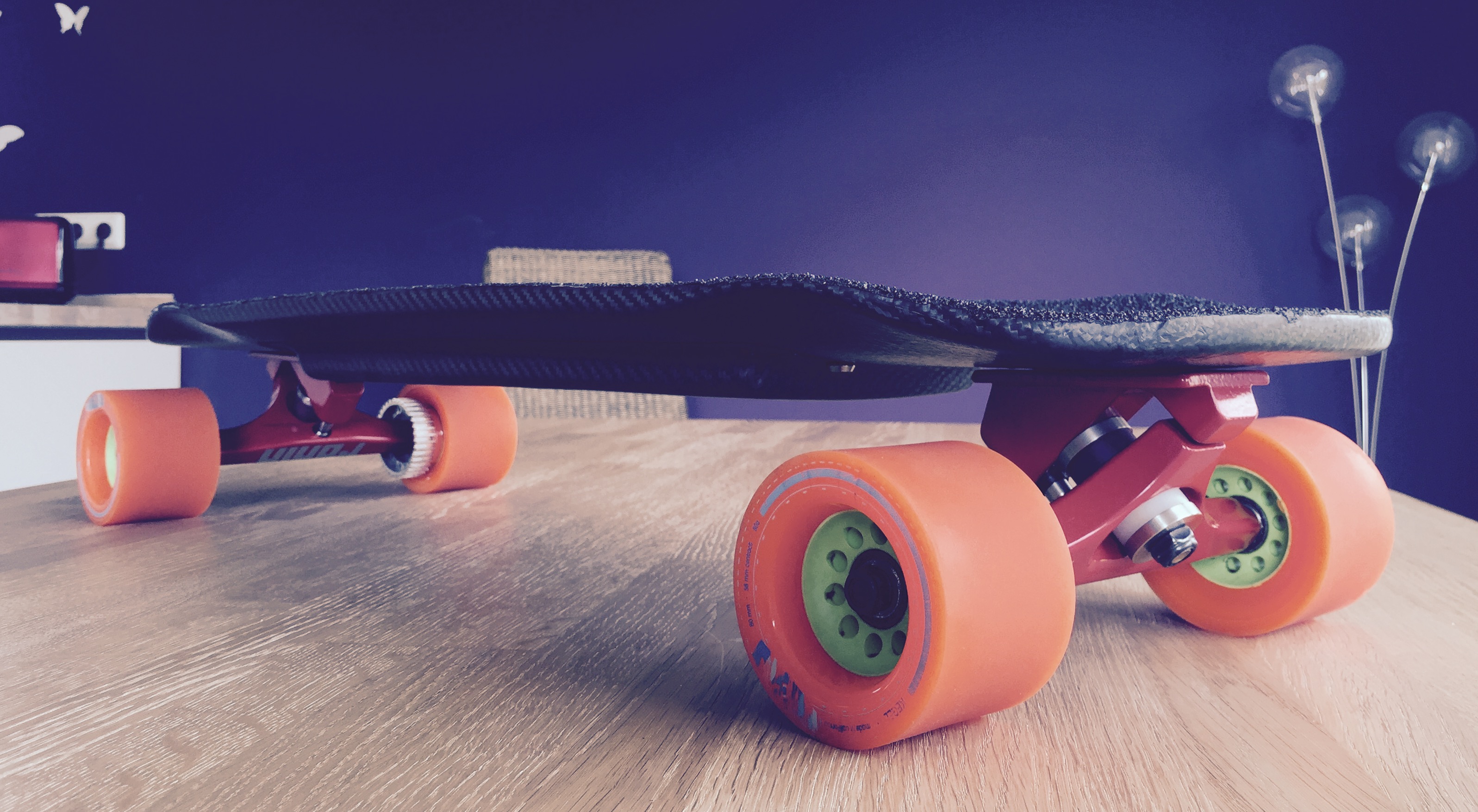
trucks arent mounted yet, board is just sitting ontop of the trucks for some pictures
motor wire exits
fixated the enclosure just with 2 screws and even with 10 screws missing, there is hardly any visible transition between board and enclosure.
_________________
mounted caliber 44s now for real - still had those from my to be reworked topspeed build, sadly only stock bushings which are way too soft for me - got wheelbite right away with those. my beloved krank barrels should be in the mail tomorrow - turns out they didnt help either, still biting!
aaand I mounted the enclosure now as a test before I get all the electronics. actually got my cells today, so I might start working on the 10S3P battery tonight ... or I might just ride the board manually a little and find a good mounting point for the bindings. love holidays, so much time to do just what I want 8)
anyway, a few pictures of the mounted enclosure - love the screw combinations that took me a while to set up (its a flat countersunk torx screw with a countersunk washer and a 1mm thick rubber washer):
_________________
made the battery today, going quicker everytime really.
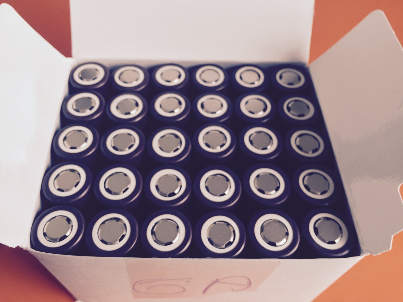
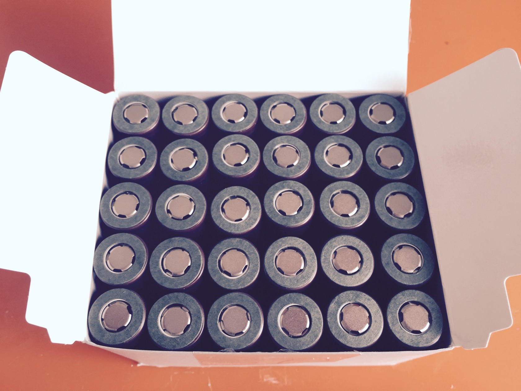
30 cells LG 18650HG2
added cardboard shield to prevent shorting of plus with the negative shell
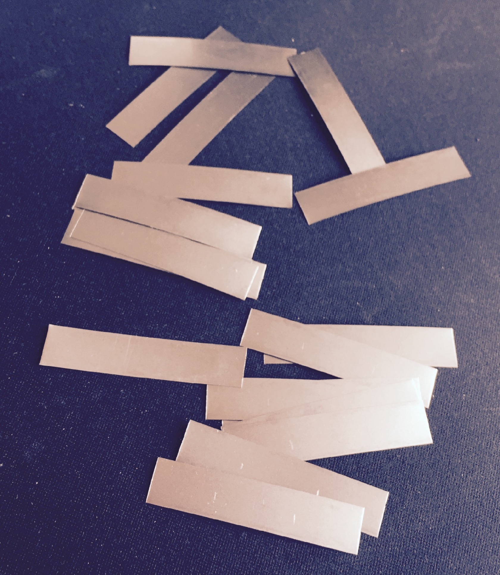
cut 20x 10x0.15mm nickel strips
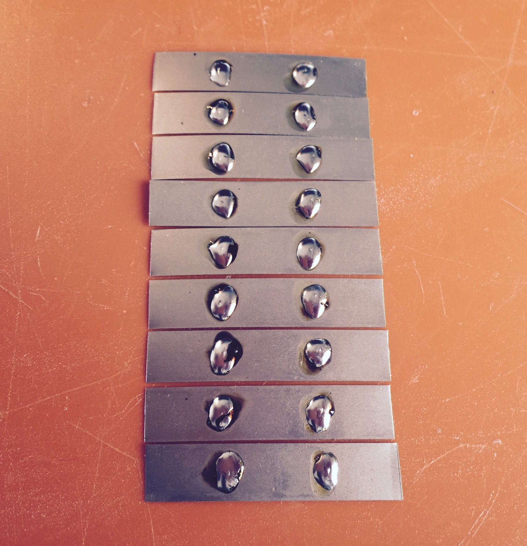
marked 10 of them with my knife and added flux to that spot for later serial connection reinforcement
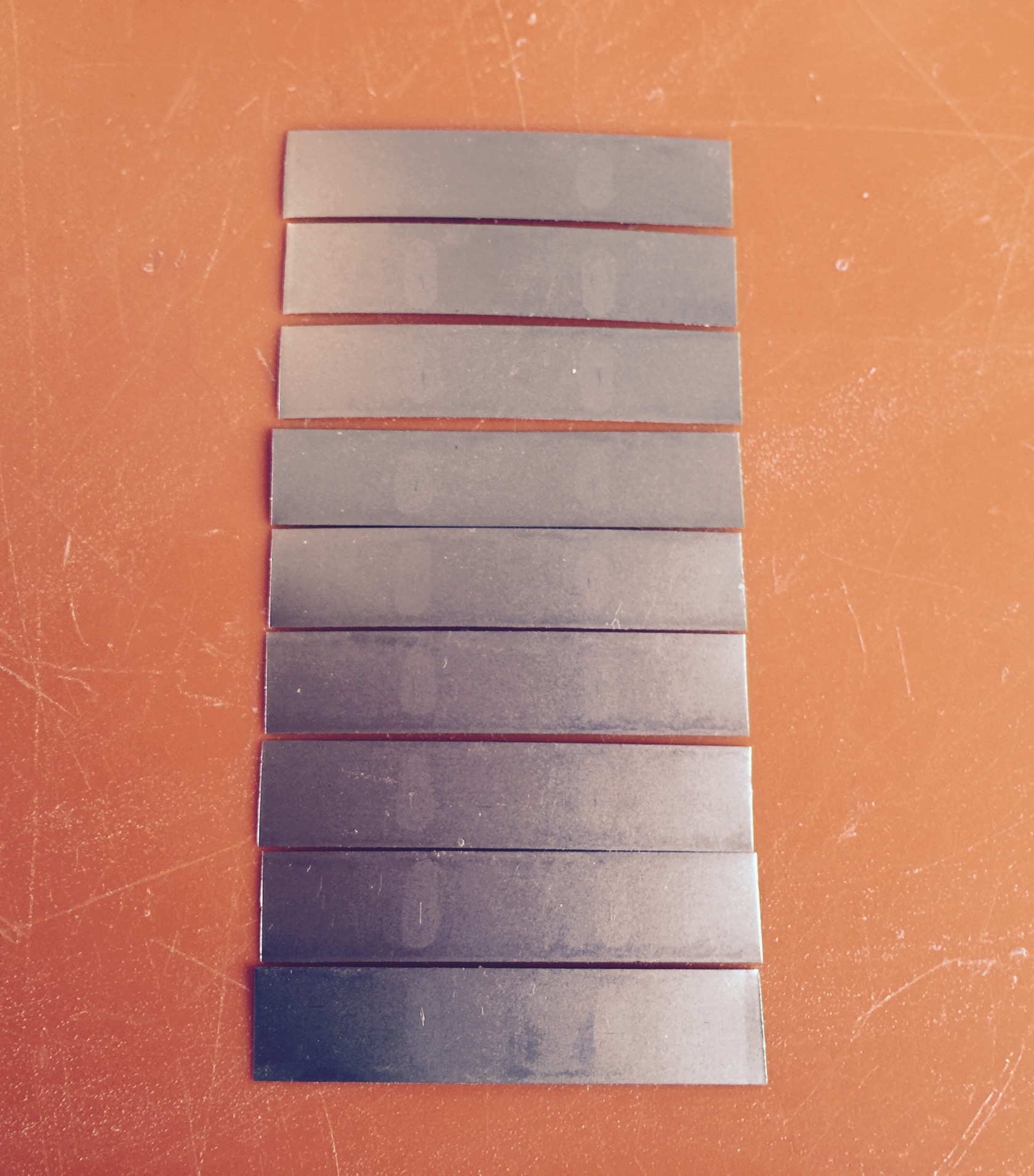
set up solder spots. yes, its only 9 because I forgot one ..
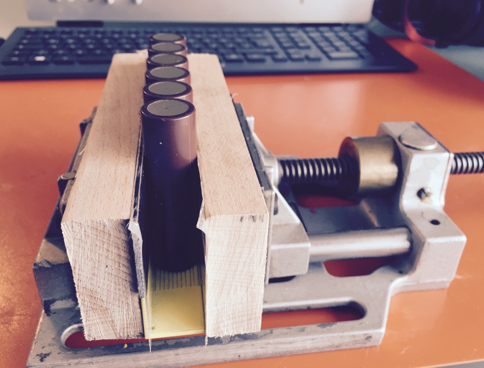
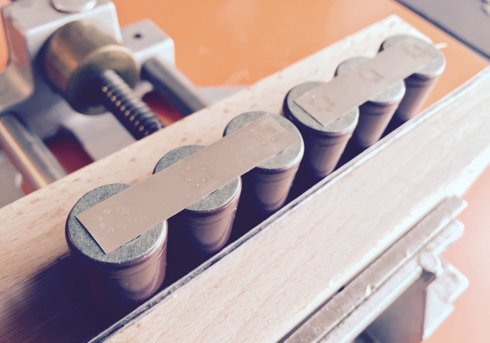
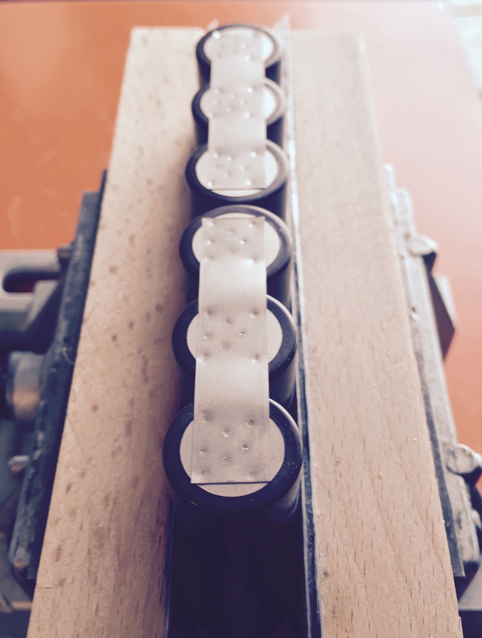
my vice, set up with 2 pieces of wood and an angle to keep cells aligned. with only 3 cells parallel, I was able to do 2 parallel packs at a time
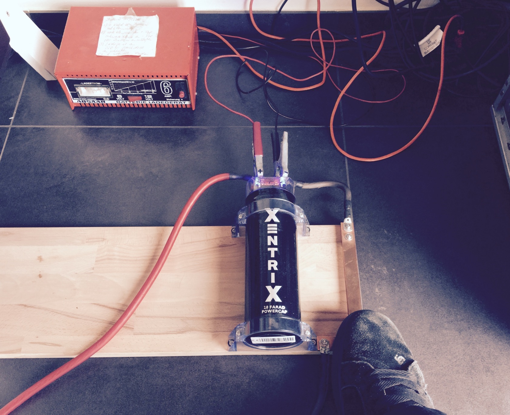
off to welding - my fabulous stoneage DIY spotwelder - a superold battery charger, probably from WW2, directly connected to a 2F supercap. when I want to weld, I stomp on the DIY copper switch, basically 2 thick copper bars that will touch briefly. in order to avoid that they weld together, I put half a skate truck bushing between them to reliably separate after each welded spot!
it works well though - plus sides with the small pole:
and minus side with more room to work with
all 10 packs done
adding some hot glue to avoid that the shells will work on each other
then doing all serial connections. the middle of the battery by 3 nickel strips each (its not a lot, if I assume about 15A per nickel strip its just 45A, but that works for me in a max 60A continuous battery).
the "outer" connections I did with 2x 5mm wide copper wick each, because a single nickel strip feels a little too small for the typical currents
plus and minus side has a little extra copper wick to attach the battery wires - I usually go with 10AWG, but I think this time 12AWG will do. taking the isolation off, then splitting the small copper wires inside in half, putting the dual copper wick in between and clamping the split sides together.
this makes for a very nice joint after soldering
finally thick shrink tube with glue inside and bending the wire in the correct form while the shrink tube is still hot
then fixating the wires with some scotch tape and folding the battery like a butterfly. the minus wire is running in the channel made by the 20 serial connection nickel strips (that I covered with thick adhesive tape)
no balancing wires - Ill check back on the battery in a few months for maintenance and measure the serial packs manually. I dont expect any drift because all my other batteries also never showed any drift. but who knows, this is my smallest battery - maybe with more load Ill see some drift eventually.
finally shrink tube and a quick weight check: 1500gr!
while the deck weights only 1241gr!!
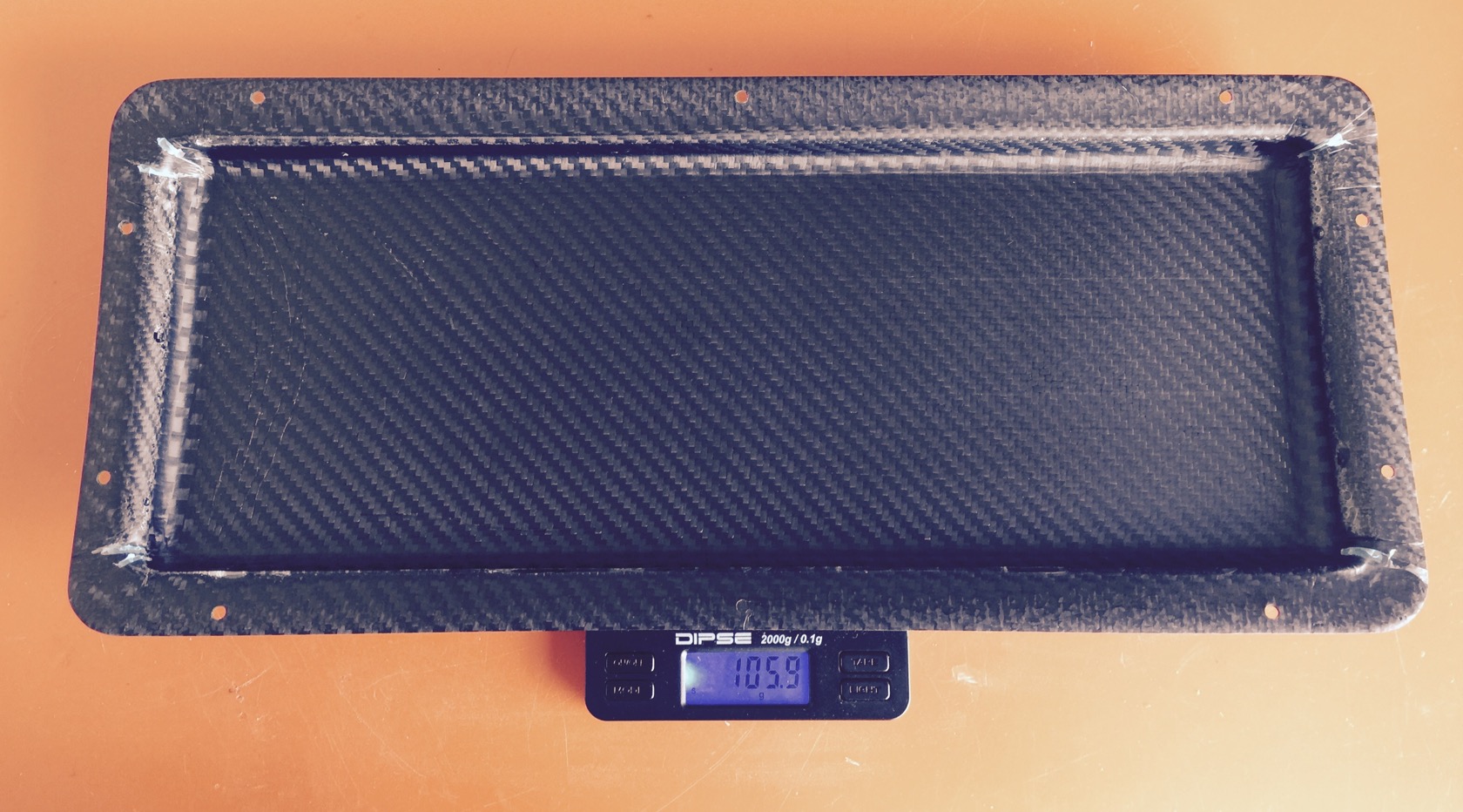
and the enclosure 106gr:
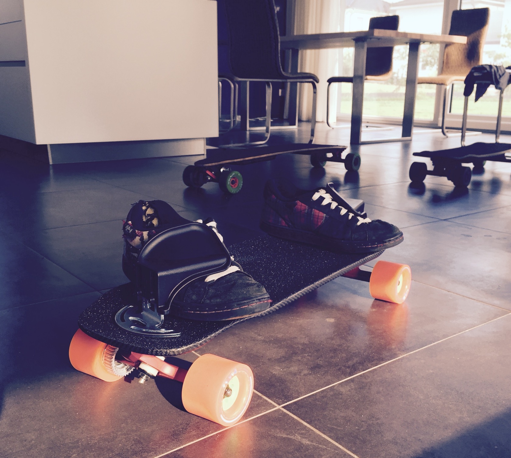
fitted the bindings with my most beloved pair of shoes - turns out the outer truck mounting holes are perfectly aligning the bindings with the wheel wells which is my favourite stance - just slightly touching the wheel wells from the inside.
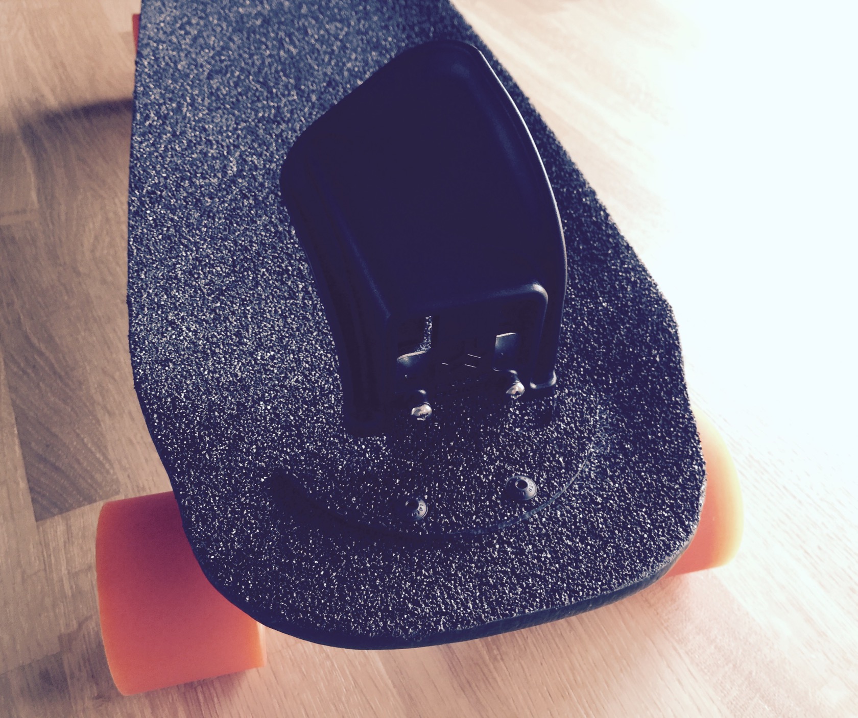
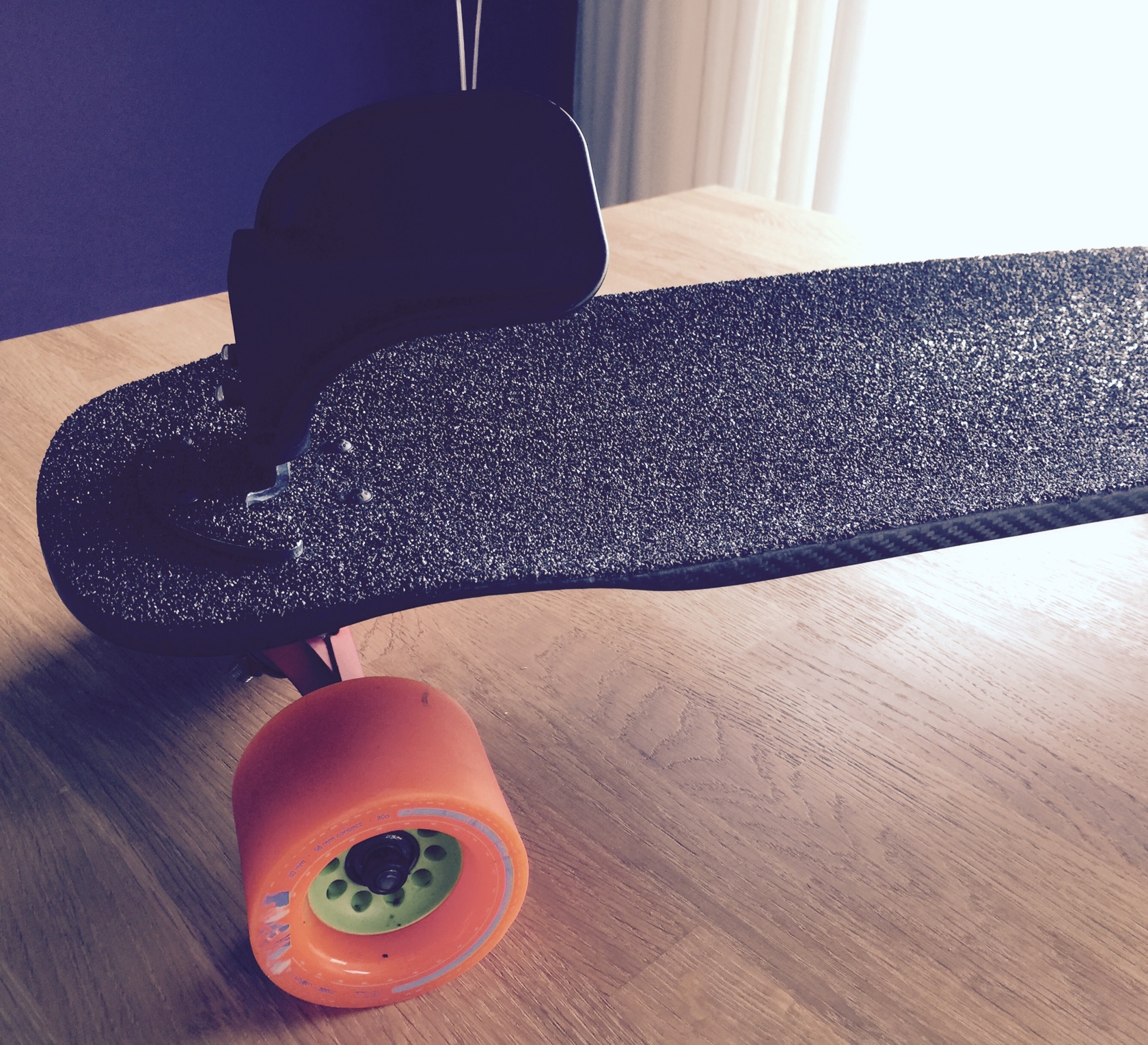
fixated them properly and covered the ugly bindings (presumably zinc plated steel?) with leftovers of my vicious griptape:
that same night I practiced some ollies, which is kinda weird since you cant pop the board - feels (and sadly looks) more like jumping. Ill have to practice to make it look cool 8)
[youtube]Vxf_qgXVmOA[/youtube]
there were a few jet spud builds in the past - torqueboards, runplayback and when I recently came across OKPs unikboard video (http://unikboards.com), I also recognized the jet spud there ... equipped with freeboard S2 bindings woot?!
no clue why I didnt think about freeboard bindings on a regular board yet. bindings are an awesome thrill that allows a lot of cool stuff, especially with a board that is probably a lot lighter compared to my trampa. since I had time, I pulled the trigger on the deck, which is pretty cheap with just 85€ incl. shipping and I had plenty of materials left for some carbon fun. the deck is really very interesting - only 29" long, but with comparably large wheelbase and also its fairly wide with a very pronounced concave and wheel wells (it still bites without risers).
this build thread focuses on the infrastructure only, i.e. board, enclosure and battery - think everyone can attach a motor mount and connect the motor to a vesc
so much for an intro, lets get to it!a rough sketch of whats to come: 38x14mm enclosure for 10S3P liion battery and 1 vesc with some electronics:
got started with some proper sanding, since I didnt like the overall finish and build quality of the board. wheel wells werent symmetric, the wood under the sketchy graphics was rough, truck mounting holes were larger than what they had to be, but found out quickly why: the drill spots werent very exact and barely fit my testmounted trucks.
then I started drawing (which works a lot better on wood than on graphics). Had a quick sketch ready on keynote for single vesc and a liion battery and found out quickly, that by taking the wheel wells as enclosure limits, only a 10S3P liion battery was possibly on this board. so far I really loved 10S4P - its a great blend of power and durability. 10S3P will have to work here though, nothing else possible and I think a little less weight probably suits a freeboard well.
just added the ronins and kegels for some visual impression - got these wheels and trucks since forever in my treasure chest and never got to use them properly. when I tried to downhill the board without motor, I found the ronins too agile though, welt a little scary around 40kph.
off to routing the electronic compartment - I made some router guide with that straight piece of wood. you can see one routed line there already, nice and straight, much better than free hand routing (which was kinda my first attempt to it a while ago). I carved out wood of 6-7mm depths.
2 long sides done, now the perpendicular sides to have an outline for the rest (which I did with a wider routing bit and without any router guides).
done, some sanding and I called it a good first evening. that 6-7mm depth was REALLY a lot, I think there are just 2-3mm left on the board - sounds really hollow when I knock in the middle region and it feels like I could break the board by hitting the middle hard. gotta need a lot of carbon to restore the structure:
the next day I decided to push things a little further: planned to sink in the enclosure lid like on my evolve board, so that its actually on level ground with the rest of the roadside board surface. this will also make it much easier to trim the enclosure later when its done, since it will act as an automatic trim guide.
used a large nut for a nice rounded lid:
and some routing, I really was extremely careful not to screw it up since, unlike the middle routed box, the sunk in lid will be visible from the outside. I also drilled mounting holes already for M4 inserts, so that those will actually be protected and not visible under the carbon.
few more impressions:
had some burn marks from the router bit because I was very careful and worked very slowly
added the m4 inserts ...
... and used filler to get rid of the 2nd pair of mounting truck holes and some imperfections.
I actually drilled real holes into the board this time for the inserts. my plan is to lay a few layers of carbon roadside to restore the boards structure, then use a very slim drill bit to open the carbon in the right places from the boards topside! the carbon and resin will keep the inserts in place nicely and the inserts will be actually mostly covered by carbon except for the small m4 hole!
problem is with these inserts: sometimes, and only when used with loctite, the inserted threads will come out - set under carbon and resin like that, it certainly wont happen. topside of the board will get the same treatment later, so the inserts will be stuck between 2 resin carbon sheets and that should properly seat them for good!
anyway, to actually lay carbon, I didnt want the resin to fill the threads of the m4 inserts and exit on board top side, so I added m4 screws into the inserts. Im a little worried about that, not sure how strong the resin bond will be.
threads are covered! quick note here before Im off to vacuum bagging: on all pictures you can see that the surface isnt actually supersmooth, but sanded with quite rough grid (P40). I did that on purpose to allow a the strongest bond between maple <-> resin & carbon layers!
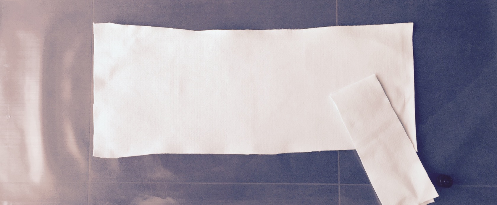
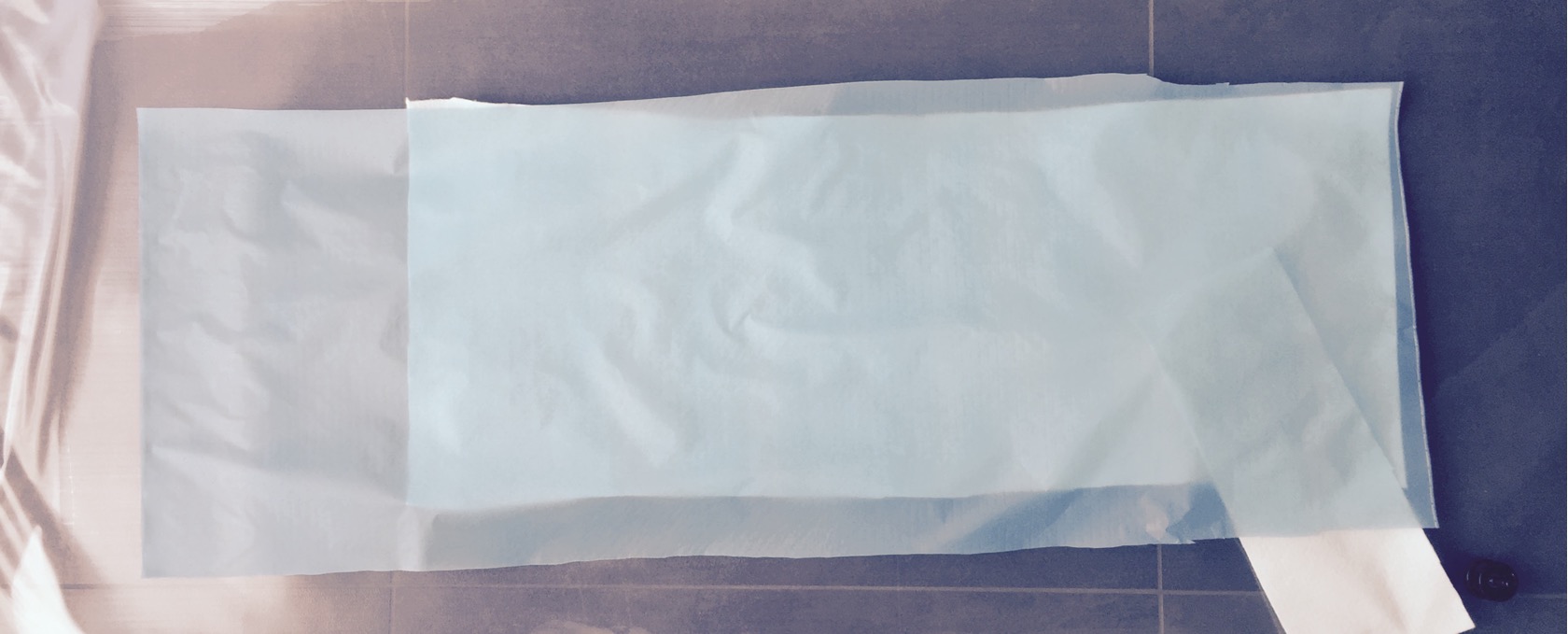
preparations for vacuum bagging: starting with the last things first and then working my way from the top when the resin is set up: vacuum bag prepared, the soaking breather layer, that also allows the vacuum pump to reach every spot evenly cut into the right format!
bleeder layer - basically a release film with small holes in it, so resin can transfer through to be soaked by the breather layer:
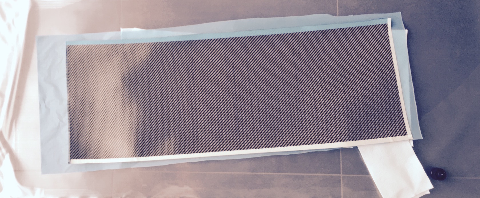
nice air grade carbon twill for a sexy finish:
a small tip: when you cut carbon or glas weave, take some painters tape and tape the outline directly on the carbon, then cut right through it! like that you wont have fibers flying around all over the place and the carbon wont fray on the edge:
last thing and basically first layer when I start the layup: unidirectional carbon to max the strength of the typical skateboard load (bending towards road between the trucks).
the layup will be 1x unidirectional carbon (which is a little stiffer to work with and 2x carbon twill, then add the bleeder, then breather, then put it into the vacuum bag and switch on the pump. I really dont think 3 layers is enough to fully restore the boards structure, but Ill add one more gfk + carbon layer ontop to cover LHB-style motor wires (more if I feel like I need it - will do a careful load test after the 3 current roadside layers have cured).
sadly no pictures of the layup - couldnt take any with soggy resin hands and I try to work swiftly because the resin keeps curing.
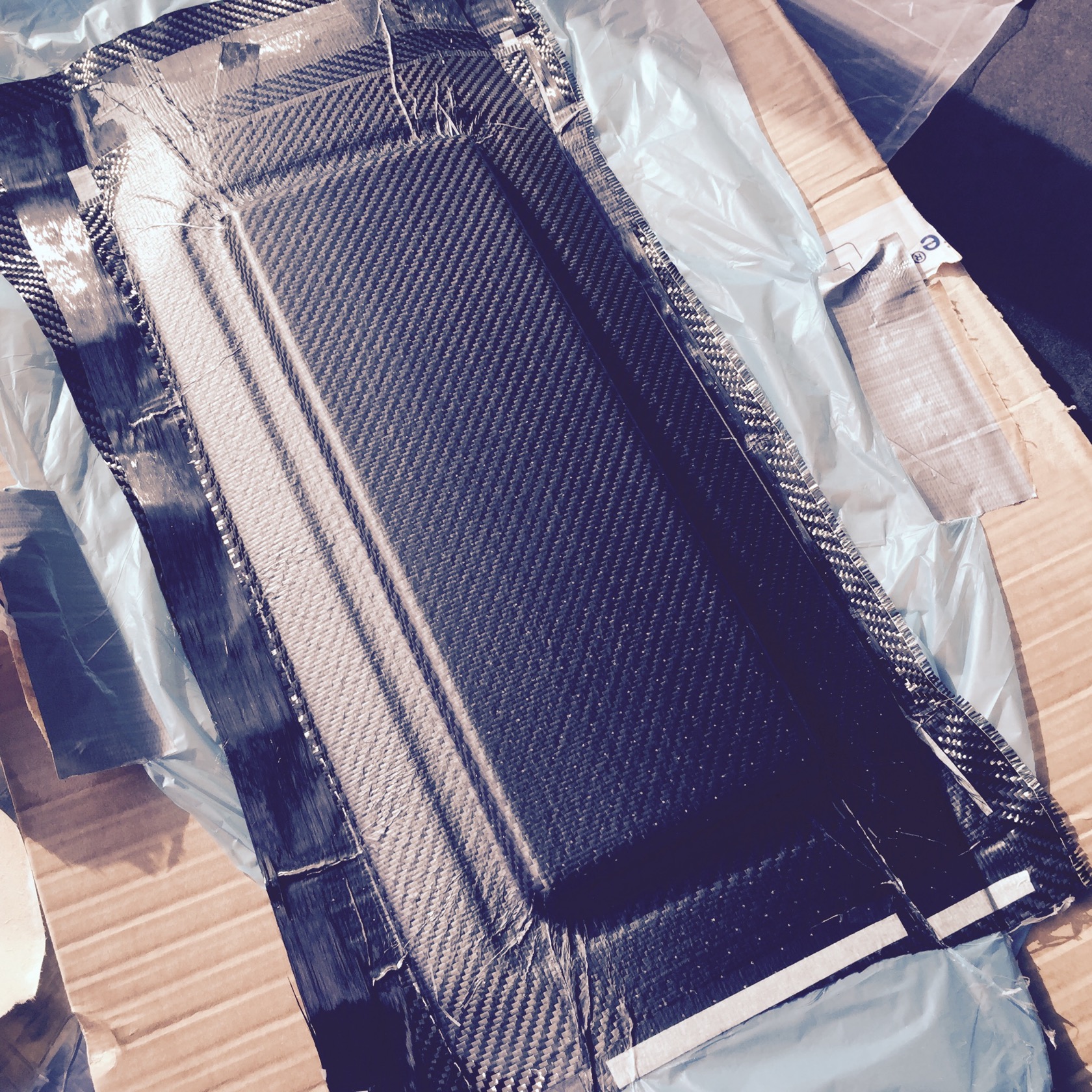
when I switched on the pump, I used the vacuum bag and the increasing pressure of the bag on the board to smoothly wrap the carbon all around the edges (hard to explain - usually a vacuum bag wouldnt put pressure on the edges really - or straighten them out or wrap around the board). this time I wanted the boardedges covered with carbon - for looks, but mostly to add further structural support and its not THAT trivial to actually get a tight fit and pressure around the edges of the board. I drew a picture to explain it - basically, with rubber gloves on my hands, I pulled the bag towards the middle on topside with really a lot of force while the pump kept applying more and more pressure on the bag.
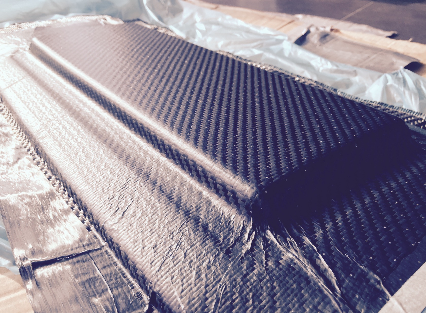
ontop of that I also used a pretty sharp edged wood block to stretch the vacuum bag in the right spots so that the routed electric compartment will have sharp edges. if you dont do that, the edges will be very rounded, with air or resin below the carbon weave and youll lose a lot of your enclosure surface by that.
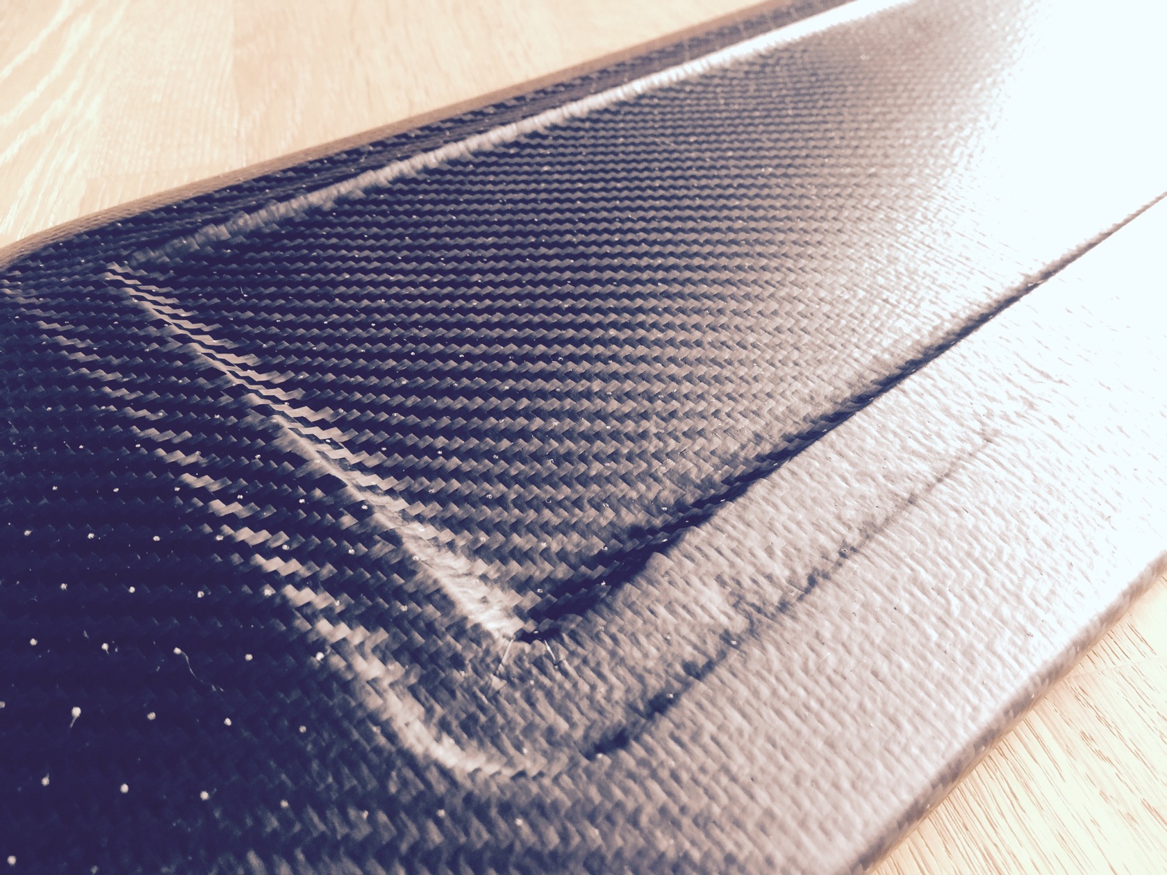
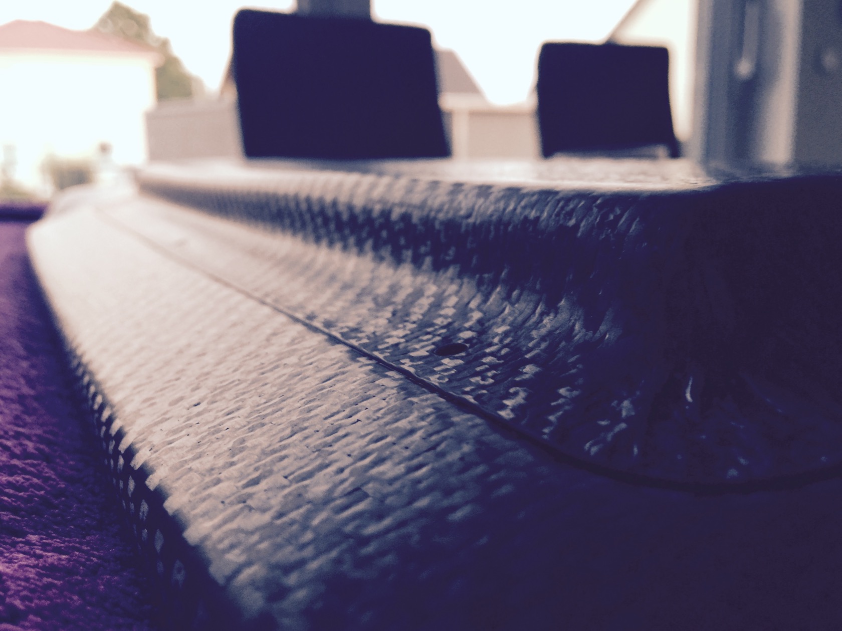
fairly sharp contours - this will be one of my sharpest vacuum bagging features on a board so far I think.
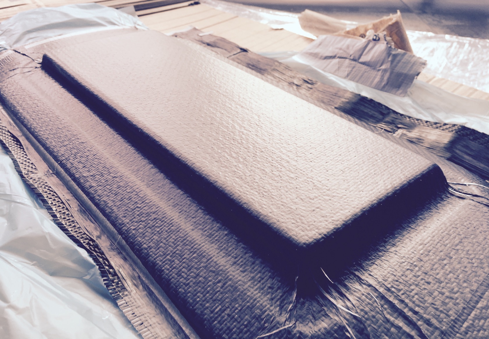
here you can see the roadside result of how I wrapped the vacuum bag around the board:
thats it for now - time to clean up and wait for the resin to cure (24h).
________________________
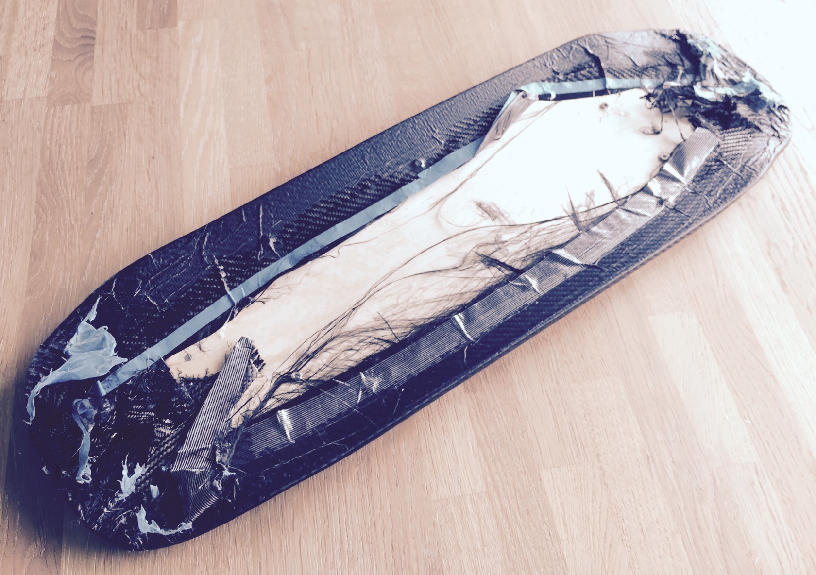
I already noticed when I left the board for curing that the wrapping of the carbon around the board will leave a mess on topside. partly the screws were covered, resin soaked weave everywhere and it wasnt always just flat, but crumbled. long story short: topside WAS a resin crusted mess.
but lets start with the good things! thats how the roadside came out - no sanding, nothing, just removed the breather and bleeder layer.
you can tell its fresh from the vacuum bag from the small white pimples on the carbon. these are the tiny holes of the bleeder layer, where the breather layer gets stuck a little bit.
ok, turning it around ... argh
this would be a mess for sanding, since from sanding heat, the resin becomes fluid again and then it clogs up your sand paper instantly. also I was super afraid of the screws - looked like the resin actually found its way through the inserted threads and came out on topside, seating the screws nicely.
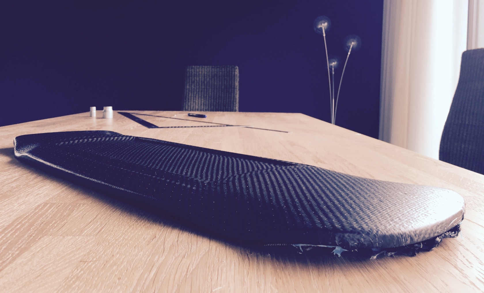
but I mean, at least the board edges are well covered by the carbon - looking good overall except for the topside mess.
alright then, my favourite hobby: sanding in the burning midday heat with 50% humidity and a dust mask against the carbon dust.
more or less done - the rest is cosmetic litte stuff Ill do before I lay another gfk/carbon layer after motor wire channels. thank god the screws came out and the inserts stayed - I used special screws with a large torx head so that I really could grab them with some torque without killing off the head. all of them came lose after instant full torque with the cordless electric screwdriver and at least the inserts appear to be really strongly bonded with the wood resin and carbon.
rest of the board has turned out nicely. pimples gone, sanded under water with 280, then 600 grit.
and 2 more perspectives
__________
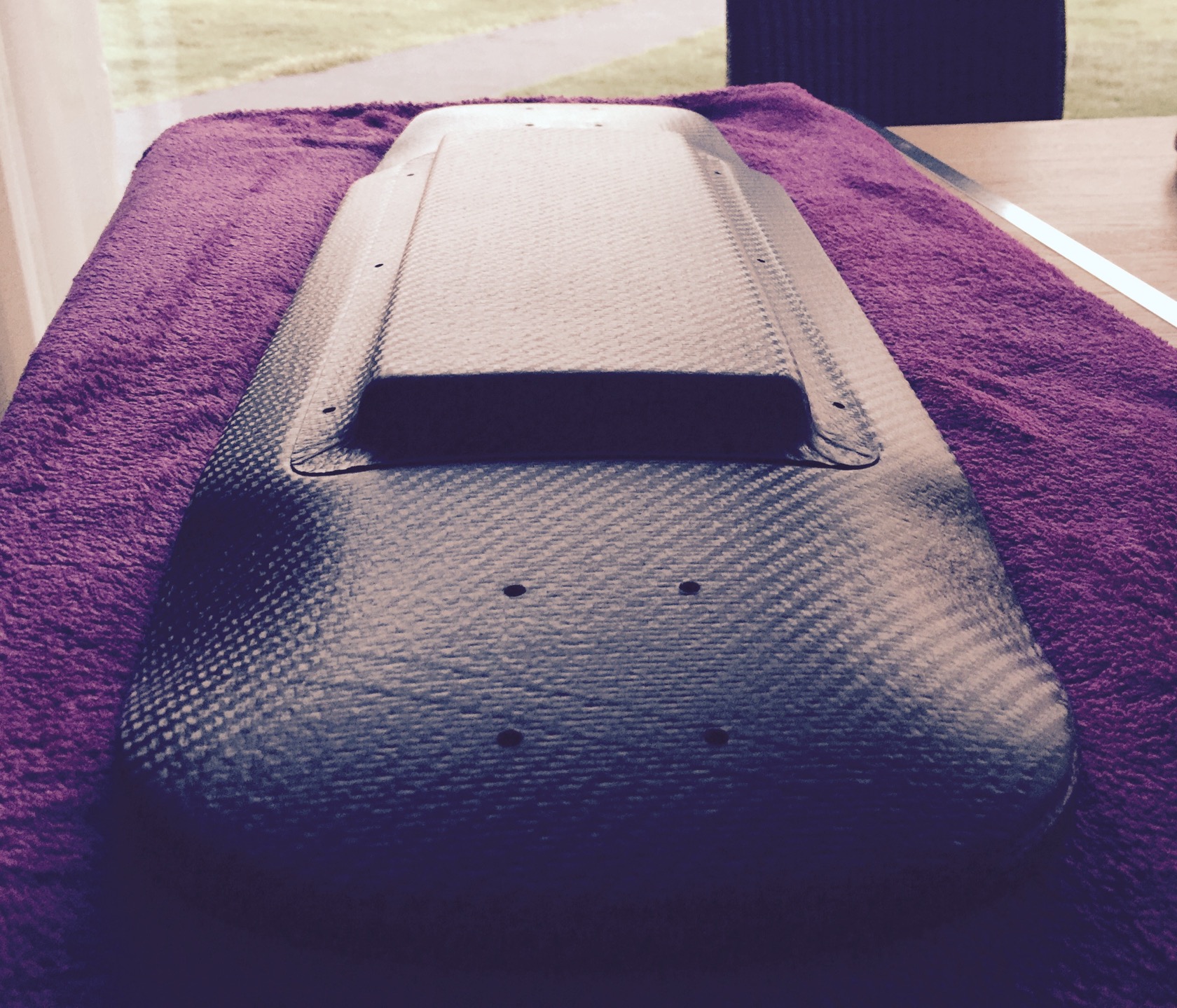
the same evening I started with the enclosure made by a foam mold from 30kg/m^3 XPS foam thats supposed to be a little more rigid than my bad other foam experiences where the foam gave in under the pressure. against all odds and a clearly visible dent through 2 layers of breather, the enclosure came out great!!
very smooth top
nice and evenly rounded edges
usually you have these crumbled edges where the bleeder foil is crumbled. no idea how to get around that. its easy enough to sand though!
and a slight concave following the routed compartment. thats the cool part of the hard foam mold - it follows light curvatures just from the vacuum pressure!
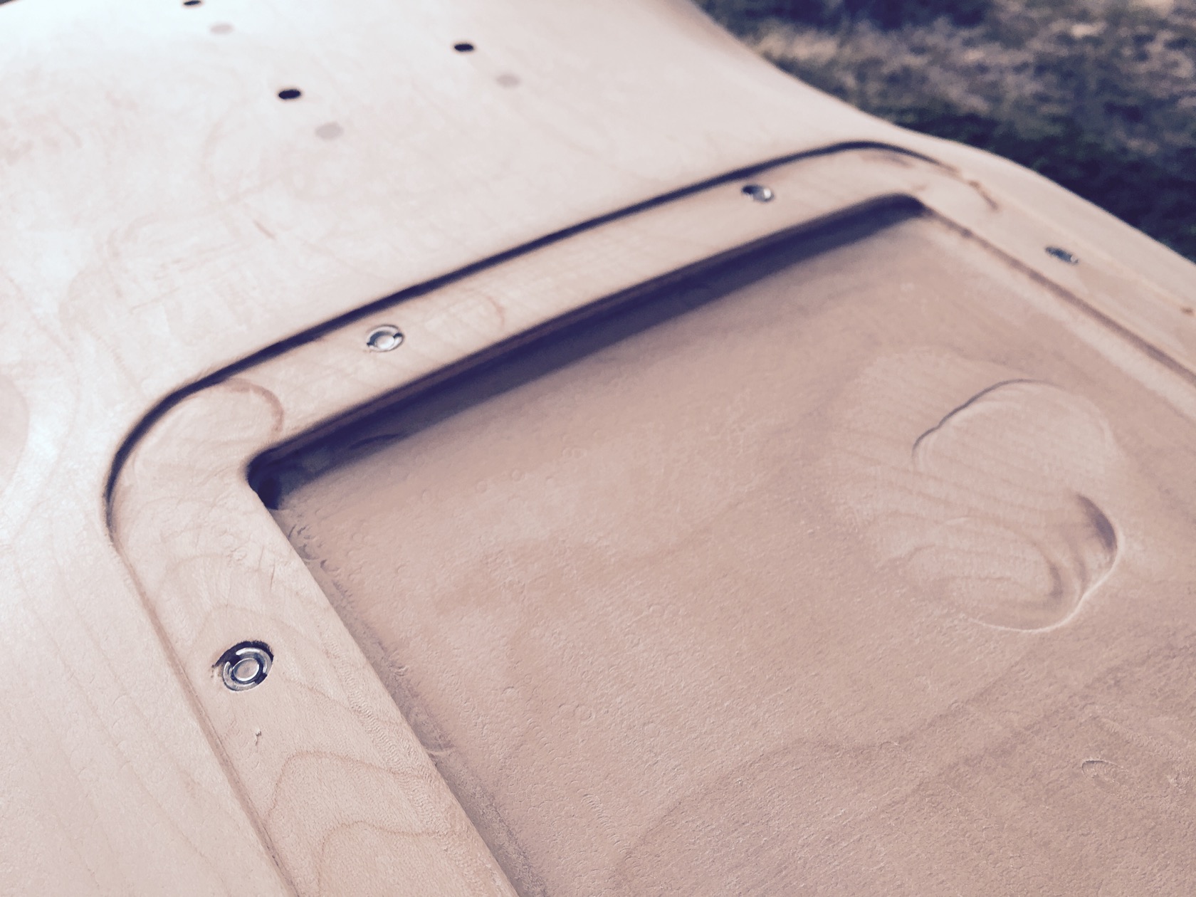
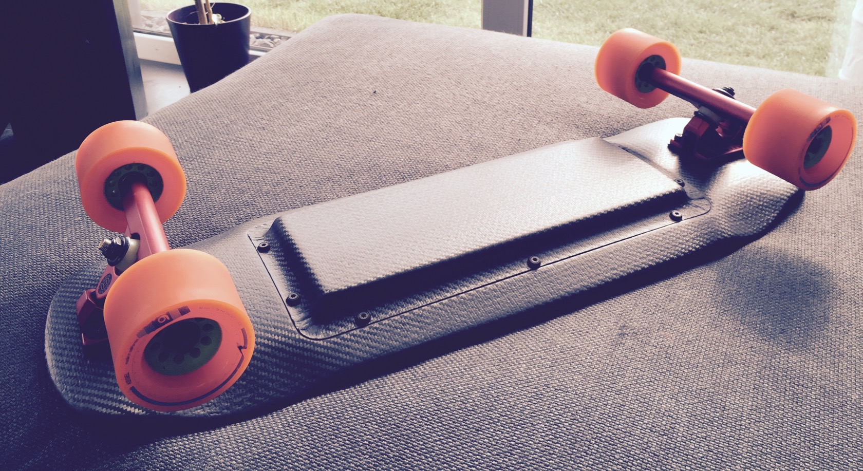
back from cutting, sanding and drilling holes! it was a little dark already, couldnt take any nice pictures with sunlight on the carbon texture anymore ... but got a few impressions at least.
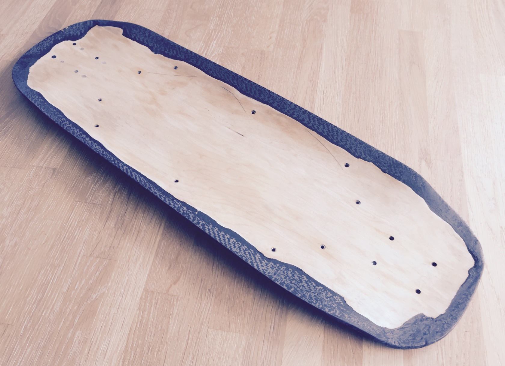
starting with drilling holes from the boards topside right through the boards roadside carbon layers and the enclosure lid with a 3mm drill bit that wouldnt hurt the M4 threads of the inserts. you can spot the tiny holes if you look closely! I left the foam mold on the board so you can have a look at it - its very simple, all I did was cutting a correctly sized rectangle from a larger industrial XPS foam plate and rounding the edges a little. note how I also rounded the boardside edges because of the rounded edges of the carbon compartment in the board - the vacuum bag will pull the foam down to the ground of the compartment and bend it smoothly around the mild concave - but for that to happen the foam piece had to be a perfect fit for the rounded carbon ground!
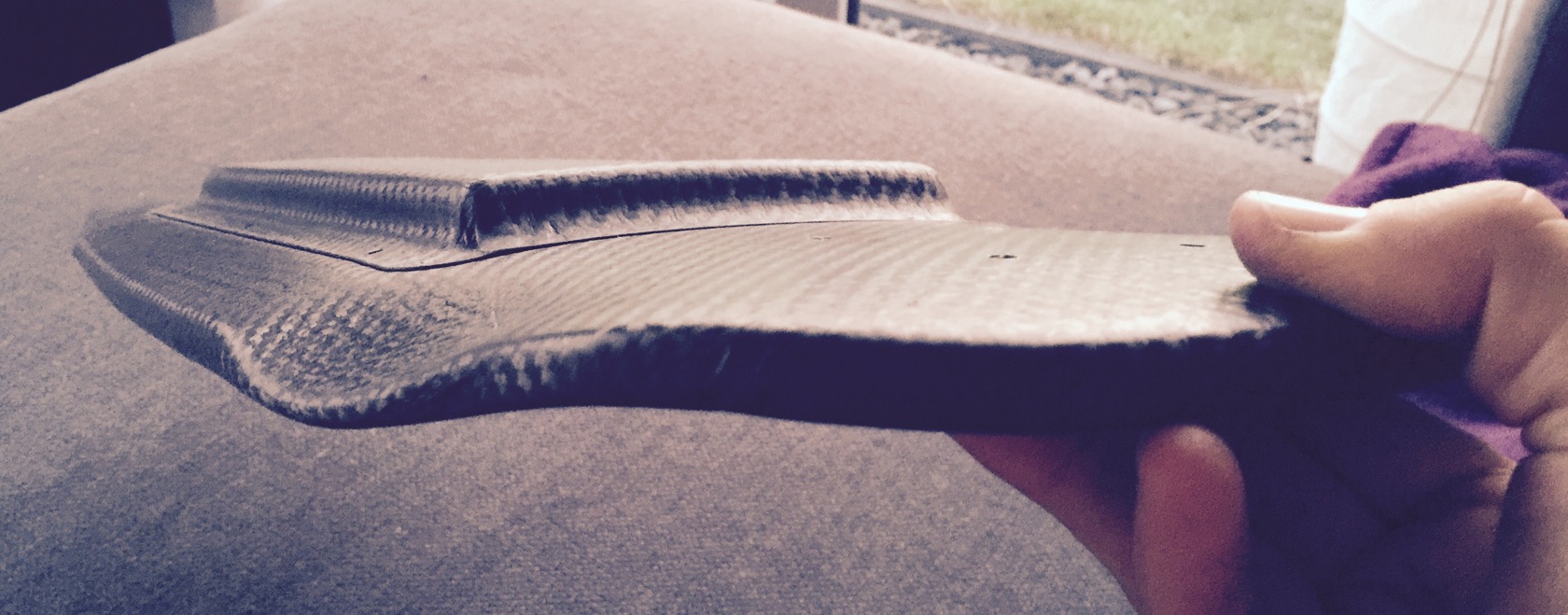
frock yea, you can see right through all 10 holes WITH the enclosure attached!
and the m4 inserts are perfectly hidden under the carbon:
enclosure is a nice fit, it actually sticked to the board from the adhesive effect of water alone
transition board surface <-> enclosure is ok, I couldve cut the lid a little slimmer, but didnt want to cut too much around the drilled holes.
note how the texture of the enclosure carbon perfectly transitions into the texture of the board carbon 8)
its really slim
___________________
finally working on the motor wire channels on the boards top side. started with drawing - this time no silly rectangular shapes but something that the 3 parallel wires can actually follow:
exiting right next to typical rubber pads, which are a little wider than most truck baseplates:
routing, this time by hand since the geometry and the router base plate didnt allow to go with reasonable guides. it was quite messy, because with the big router baseplate, I routed a lot of different and varying depths, so I had to adjust height frequently, reroute, repeat. a little annoying and not very surgical like my electronic compartment. but it works and wont be visible anyway, 3x 12AWG wires in!
and they exit directly in the electronic compartment:
my useful little helper for the 90° bullet connector insert:
really a lot of tin and allowing it to sink in really deep
3 wires done, now off to heat shrink
got very thick shrink tube with glue inside, because I dont want them to short the motor phases via the carbon roadside. this shrink tube is really super sturdy!!
hammered them in (6.5mm drilled holes just barely fit, I really cant remove or stick them in further with my hands, had to use the hammer
glued the wires to the wood and closed the exits with glue too
this time no resin mess, just used putty to level it out. Im not sure if this will stay intact, but Ill try. really didnt feel like resin, gfk, vacuum bag, wait for another 24h, screw up the roadside carbon finish, because resin somehow always finds a way to make a mess...
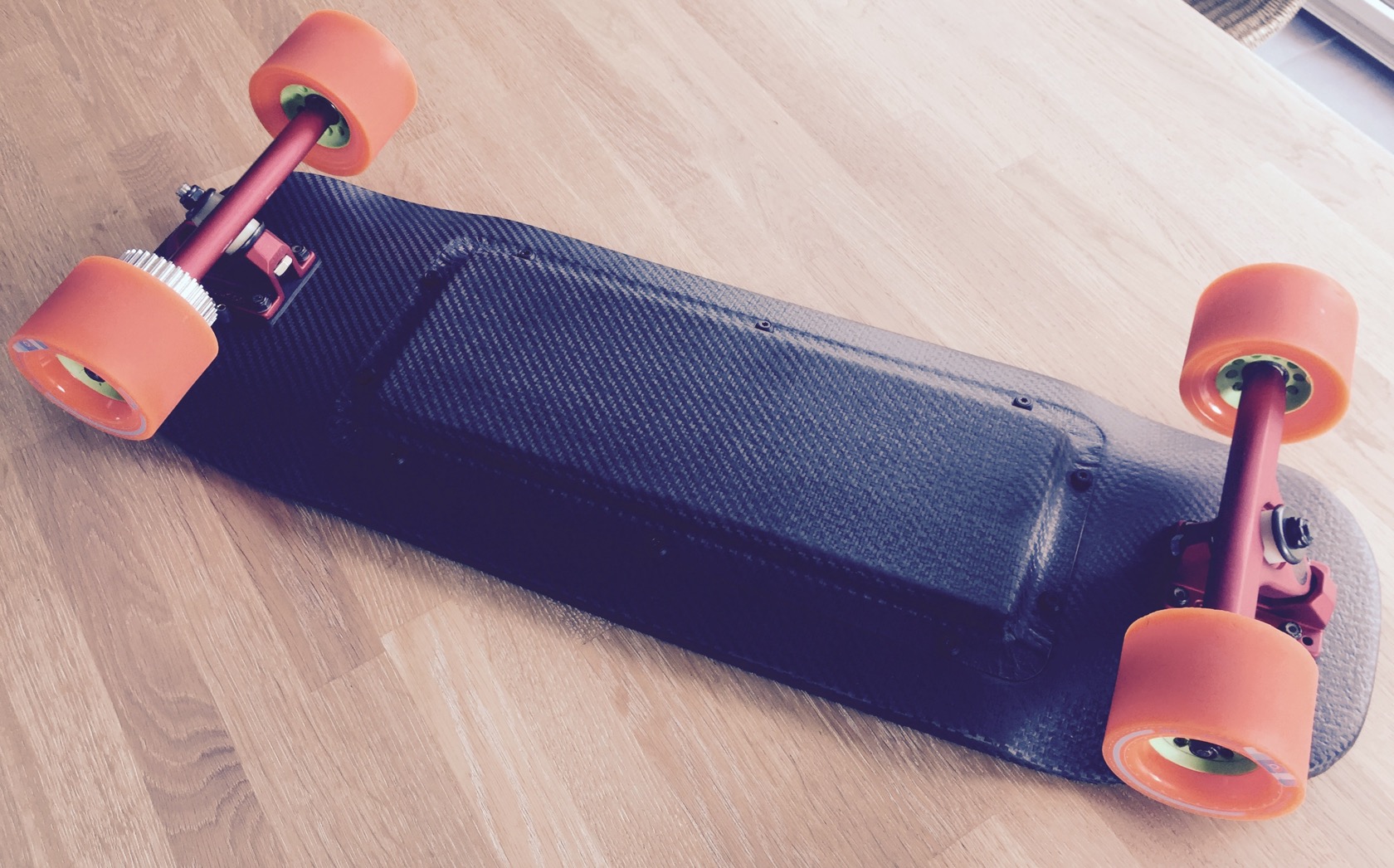
apply vicious grip and we are basically done here for now:
trucks arent mounted yet, board is just sitting ontop of the trucks for some pictures
motor wire exits
fixated the enclosure just with 2 screws and even with 10 screws missing, there is hardly any visible transition between board and enclosure.
_________________
mounted caliber 44s now for real - still had those from my to be reworked topspeed build, sadly only stock bushings which are way too soft for me - got wheelbite right away with those. my beloved krank barrels should be in the mail tomorrow - turns out they didnt help either, still biting!
aaand I mounted the enclosure now as a test before I get all the electronics. actually got my cells today, so I might start working on the 10S3P battery tonight ... or I might just ride the board manually a little and find a good mounting point for the bindings. love holidays, so much time to do just what I want 8)
anyway, a few pictures of the mounted enclosure - love the screw combinations that took me a while to set up (its a flat countersunk torx screw with a countersunk washer and a 1mm thick rubber washer):
_________________
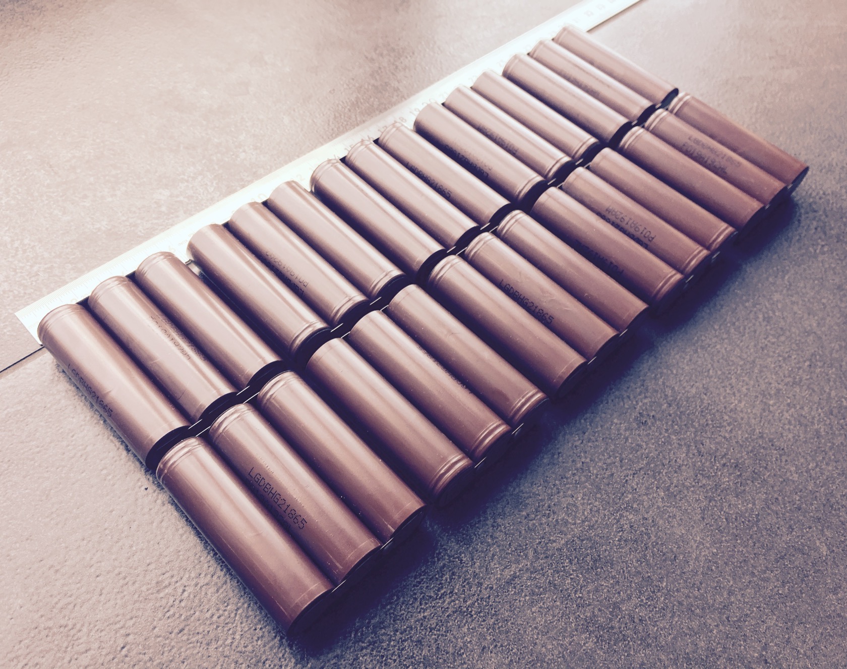
made the battery today, going quicker everytime really.
30 cells LG 18650HG2
added cardboard shield to prevent shorting of plus with the negative shell
cut 20x 10x0.15mm nickel strips
marked 10 of them with my knife and added flux to that spot for later serial connection reinforcement
set up solder spots. yes, its only 9 because I forgot one ..
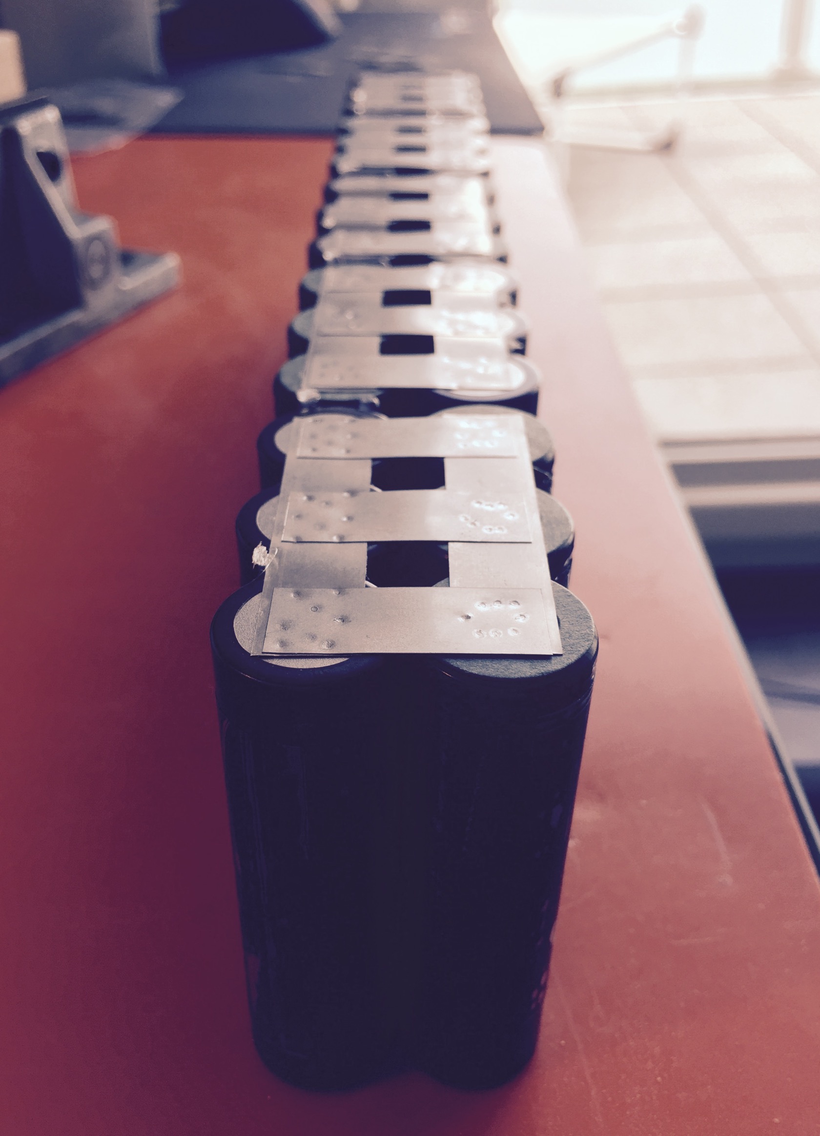
my vice, set up with 2 pieces of wood and an angle to keep cells aligned. with only 3 cells parallel, I was able to do 2 parallel packs at a time
off to welding - my fabulous stoneage DIY spotwelder - a superold battery charger, probably from WW2, directly connected to a 2F supercap. when I want to weld, I stomp on the DIY copper switch, basically 2 thick copper bars that will touch briefly. in order to avoid that they weld together, I put half a skate truck bushing between them to reliably separate after each welded spot!
it works well though - plus sides with the small pole:
and minus side with more room to work with
all 10 packs done
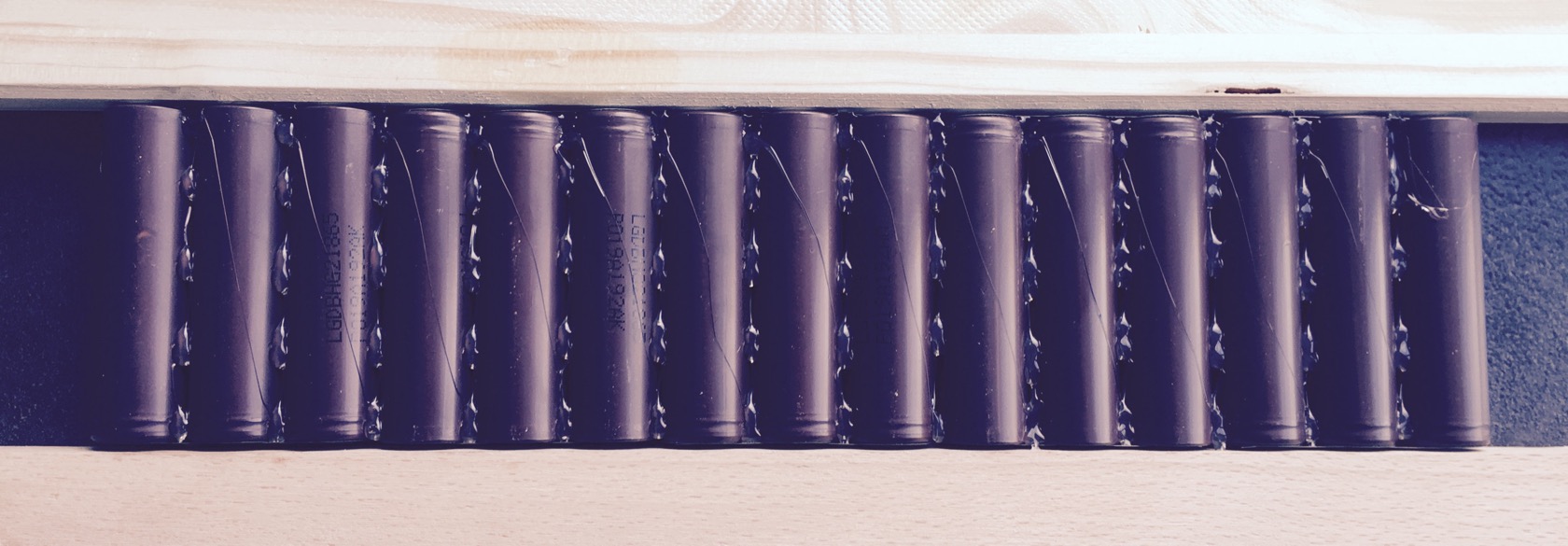
adding some hot glue to avoid that the shells will work on each other
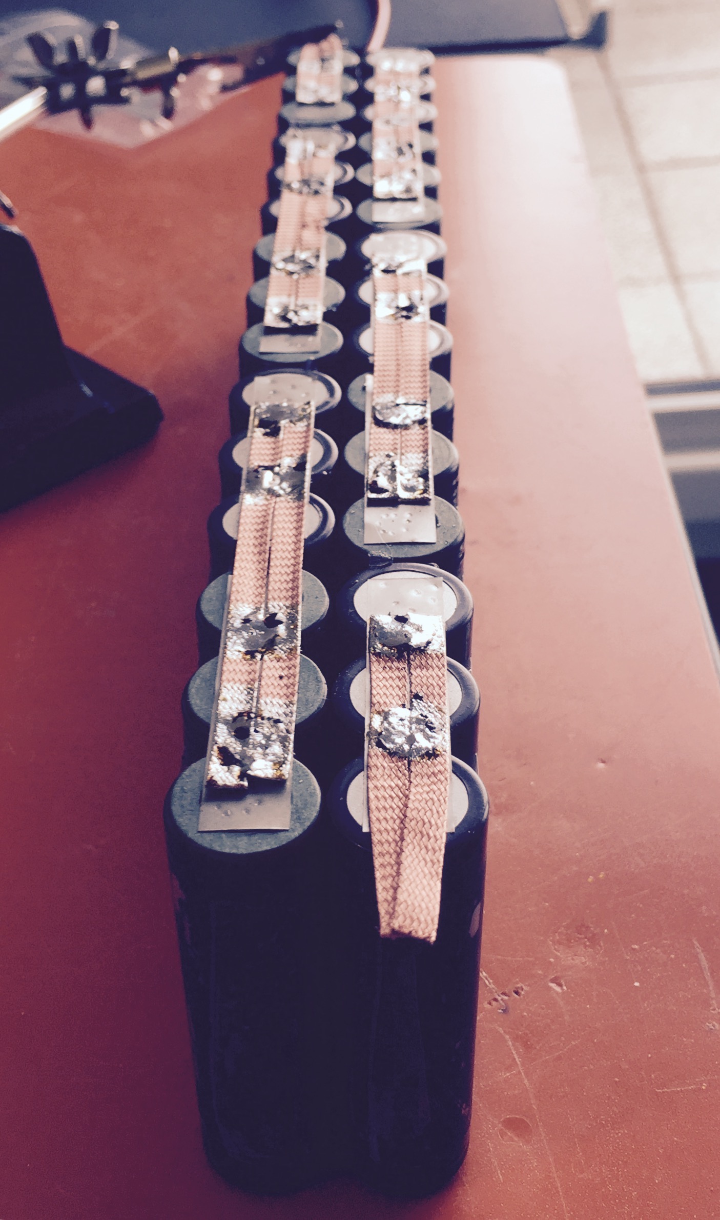
then doing all serial connections. the middle of the battery by 3 nickel strips each (its not a lot, if I assume about 15A per nickel strip its just 45A, but that works for me in a max 60A continuous battery).
the "outer" connections I did with 2x 5mm wide copper wick each, because a single nickel strip feels a little too small for the typical currents
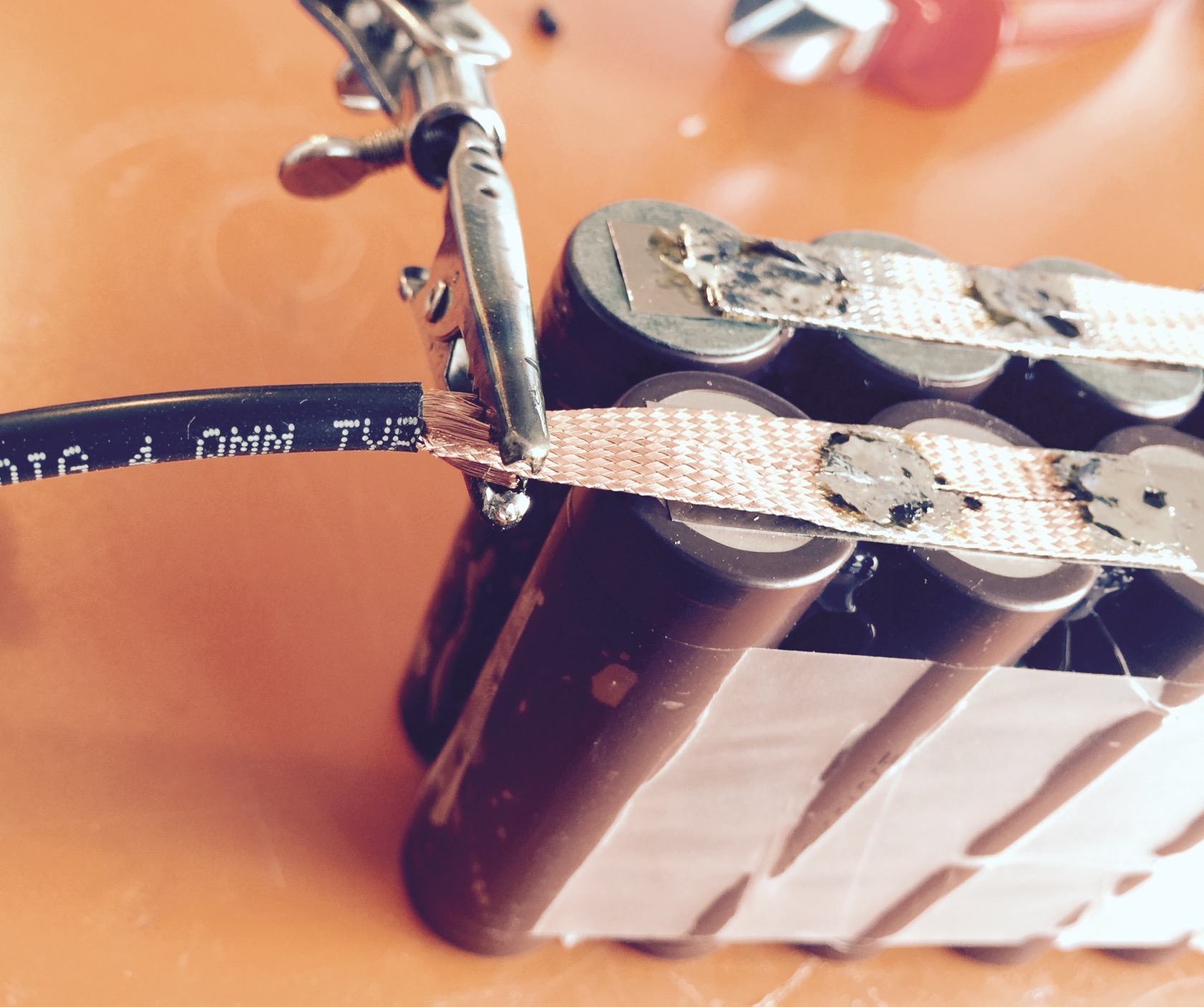
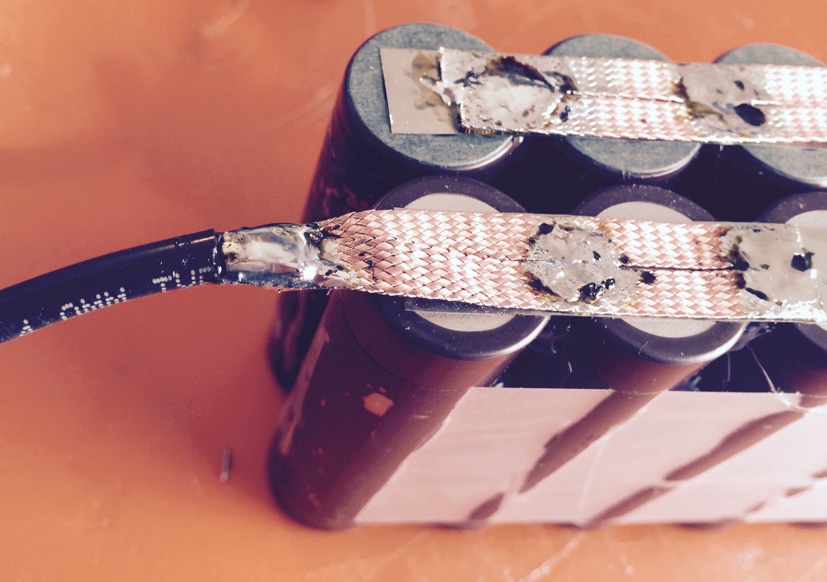
plus and minus side has a little extra copper wick to attach the battery wires - I usually go with 10AWG, but I think this time 12AWG will do. taking the isolation off, then splitting the small copper wires inside in half, putting the dual copper wick in between and clamping the split sides together.
this makes for a very nice joint after soldering
finally thick shrink tube with glue inside and bending the wire in the correct form while the shrink tube is still hot
then fixating the wires with some scotch tape and folding the battery like a butterfly. the minus wire is running in the channel made by the 20 serial connection nickel strips (that I covered with thick adhesive tape)
no balancing wires - Ill check back on the battery in a few months for maintenance and measure the serial packs manually. I dont expect any drift because all my other batteries also never showed any drift. but who knows, this is my smallest battery - maybe with more load Ill see some drift eventually.
finally shrink tube and a quick weight check: 1500gr!
while the deck weights only 1241gr!!
and the enclosure 106gr:
fitted the bindings with my most beloved pair of shoes - turns out the outer truck mounting holes are perfectly aligning the bindings with the wheel wells which is my favourite stance - just slightly touching the wheel wells from the inside.
fixated them properly and covered the ugly bindings (presumably zinc plated steel?) with leftovers of my vicious griptape:
that same night I practiced some ollies, which is kinda weird since you cant pop the board - feels (and sadly looks) more like jumping. Ill have to practice to make it look cool 8)
[youtube]Vxf_qgXVmOA[/youtube]