FOSSHW Category L7e Hybrid EV (full build: not a conversion)

lkcl

100 mW
Joined
Dec 23, 2019
Messages
39
hello folks, i thought people here might appreciate knowing that i've begun building the Free / Open-Source Hardware Category L7e Hybrid Car that i have been planning for almost 19 years, now. this is not a conversion: it is a full *from scratch* build with the entire design as FOSSHW (Free / Open Source Hardware).

the full source code of the 3D CAD is available at http://lkcl.net/vehicle_3d (see .git directory) - the License is the GNU General Public License v3 - and the video build playlist is here https://www.youtube.com/playlist?list=PLBtNqZjUZB81KyRPnMHSmX-vF8i7h5kcA

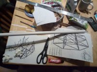
software you need is git, python2 and openscad. use "git clone http://lkcl.net/vehicle_3d/.git" and then "python2 car_model2.py > output.txt", you can view the output.txt report for lengths of pipes and the connectivity requirements to nodes. i print those out, cut them up and tape them to each pipe, as well as label each 3D printed node.

the build technique is very similar to that of the bamboo bike - https://endless-sphere.com/forums/viewtopic.php?f=6&t=118711 - although i also take inspiration from http://gaboats.com/ as well as https://calfeedesign.com/bamboo/ it's also specifically using materials and techniques that are definitively "DIY" - no toxic materials, no industrial power tools (except a welder for the metal parts), and to demonstrate that is actually true i am assembling this vehicle in my kitchen at home. which has double-doors at the back (duh).

the 3D Printer (Artillery Sidewinder X2) is cheap, cheerful, and most importantly has a Direct-Drive Volcano nozzle, which i am pushing to 100 mm/s (internal walls only), with a 0.8mm nozzle at a 0.6mm layer height. each "node" which takes around 45 minutes of which there are *135* to print is there purely for "assembly support" onto which the Kevlar / Hemp-Hessian and FR4 fire-resistant resin will be wrapped. unlike the bamboo bikes i will wrap the *entire* tube-set, in order (effectively) to create my own carbon-fibre-like pipes. i did experiment attempting to remove the formers (PVC pipe) from the inside, it went so badly i realised that actually it could simply be left inside.

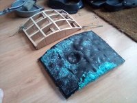
panels are a combination / advancement of the gaboats technique: two layers of dacron (fire-resistant polyester sofa covering!), separated by "label gun" plastic barbs 10mm at regular intervals, with a DIY 9x1mm bamboo lattice frame inside that is hot-glued together into compound curves. Expanding Construction Foam (again, fire-resistant from Soudal) is squirted *in between* the two dacron layers, and after 2 days it is astonishingly strong and light. the "dimples" that result are exactly like those discovered by Mythbusters to reduce drag by creating a "boundary layer" effect. i am perfectly happy with that

more later as edits progress

--------

bare frame materials (so far):

Code:
QTY 200 of 4ft bamboo poles, 8-13mm diameter
QTY 30 of 6 metre Floplast 21.5mm OD PVC waste pipe
5kg PLA (for 3D printed Nodes)
QTY 20 of 25 mm x 25 metre Painter's Masking tape
QTY 3 of rolls sellotape
QTY 4of Araldite 5 minute Rapid Epoxy glue
QTY 10of Loctite "Extreme" 50ml clear (rubbery) glue

tools:

Code:
hacksaw
mitre (for cutting clean right-angles)
600 mm metal ruler (1000 mm is better)
tape measure
sharp hard pencil
scissors
3D printer with 0.8mm Volcano nozzle (Artillery Sidewinder X2 is good)
pincer-nose pliers (cleaning up 3D prints)
fine-grade file (cleaning 3D prints and squaring ends of bamboo and PVC)
High-end laptop (with good GPU preferred) for OpenSCAD
Printer (for build diagrams)

--------

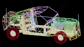
this is the 3D CAD (pyopenscad parametric) - using openscad you need an extremely powerful system. i have a 4.8 ghz 8-core i9 with 64 GB of RAM, and it is managing 3 *seconds* per frame (!)
2023-01-12_15-03.png

using the gaboats techniques for inspiration, a test panel and its associated jig, made from cardboard DIY 9x1x300 mm bamboo, and string. i should have tied string onto the lattice frame before inserting expanding foam, to ensure it does not twist during curing of the foam. the test panel was constructed precisely to find out exactly that kind of thing.
IMG_20230112_153041.jpg

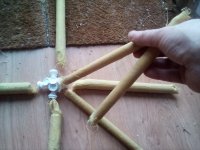
21.5mm and 12mm pipes (both PVC in this case) test-wrapped each with 3 layers of 1414 Kevlar ("aramid") coarse weave cloth and resin. this is exactly what Calfee Design and the Bamboo Bike Club do, except in this case the entire pipe is also wrapped (not just the node). otherwise the strength and rigidity comes purely from GBP 0.30/Metre PVC which is not adequate
IMG_20230112_153747_burst_01.jpg


--------

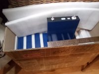
these LiFEPO4 cells are absolute monsters. 125Ah in a 2.5 kg prismatic package i am actually scared to put that metal ruler near them, knowing that it would melt if it fell across the M8 bolts on the massive 15mm wide terminals. these are Chinese Aerospace Grade batteries, normally used for very brief periods of time in high current "starter motor" applications. they have to be light and small for their power "because aircraft". a similar continuous current (125A) in the same weight and size using 18650 cells is absolutely impossible to achieve and would require 2x the weight (100 kg). given that there is a 5kW Diesel Generator continuouly charging the cells, the last thing i need is an extra 50 kg of batteries to lug about. plus space is precious.
IMG_20230112_211245.jpg

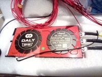
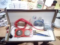
the Daly BMS, is dual-port (separate charging port with common rail), a current measurer circuit is inside. 150A supply, nominal 40A charging. i specifically asked for an external NTC temperature sensnor, and a BT adapter. they also very kindly supplied a USB-CAN-bus adapter which i didn't ask for, they just sent it. all round very thoughtful people.
IMG_20230113_182316.jpg


--------

completed bonnet:

IMG_20230111_184557.jpg

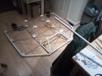
front assembly diagram (on the kitchen table):
IMG_20230111_184620.jpg

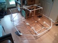
it turns out to be easier to work upside-down! this is 70% completed, and has allowed a couple of missing pipes in the middle of the bonnet to be identified. i was half-expecting them.
IMG_20230112_145648.jpg

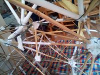
Looks like a kite: follow the green twine, you will see some masking tape wrapped around it, pulling the string *inwards*. The crosswise bamboo offcut pushes the twine apart, but often this is still not enough to generate the pressure needed to get the bamboo to sit on the Node pads at each end. Wrapping masking tape (often folded in half around the string, which has a habit of otherwise cutting clean through the tape) around the string creates extra tension. Just watch out because if the gap is seriously large (over 10 mm) you likely made a mistake (wrong pipe onto wrong Node).
IMG_20230210_130732.jpg

-------

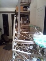
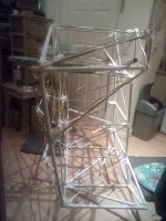
phase 2: middle section - doors, footwells, floor, dashboard, driver seat supportand roof. here is the front section (nose-down) with the beginnings of the door frame, footwell and dashboard. the cushions are there to prevent damage, not through "protection" but through "early warning". someone walks into the cushions *before* impacting the frame.
IMG_20230119_202337.jpg

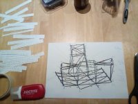
phase 2: floor dash and driver back support construction diagram, with pipe length connectivity notes with node numbers at each end, at the top left. around 100 pipes here, 32 nodes. appx same as for the middle section. roof not included here yet

IMG_20230117_040231.jpg

phase 2: dashboard footwell and front doorframe are done (right of photo. left front wheel arch is at front of photo). the middle section is not permanently attached to the front, so it can be disassembled and carried out the house. next is to extend the floor towards the driver central seat support structure (which also helps hold the roof upright)
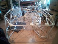
IMG_20230118_143811.jpg

phase 2: floor is now actually on the floor, half of driver seat support box is up, to be connected then continued. the 2D screenshot of the 3D CAD I am holding up in the top right, to show what is needed. it is roughly the same angle. note that the dashboard and footwell is missing: this along with 1/4 of the floor is permanently attached to the front section, because that is where pedals and steering are.
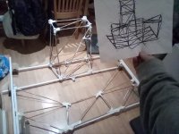
IMG_20230121_190530.jpg

phase 2: driver seat support now attached to floor, and floor support runners are in (under cushions). now the roof needs constructing, and the "back box" behind the occupants as well. the backbox is a lot of pipes, deliberately. both the rear suspension and the passenger compartment hang off it. build diagrams are marked up, lower part of backbox 3D nodes are on the table.
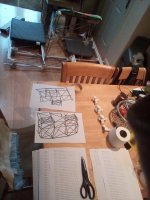
IMG_20230123_132619.jpg

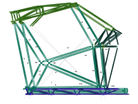
phase 2: build diagram for the side-support along the floor, similar to 1930s convertible sports cars. nodes are marked Snn, pipes just NN.
floor_support.png

--------

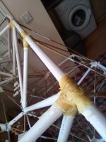
Resin stage: first Node-wrap with 50 mm special Kevlar strips from MBFG.co.uk, joining the ends of several pipes together as a first experiment. This took a *lot* of kevlar and resin. Subsequent Nodes I packed out with crumpled paper and Masking tape prior to wrapping.
IMG_20230209_150133.jpg
 
these LiFEPO4 cells are absolute monsters. 125Ah in a 2.5 kg prismatic package …….
……….. a similar continuous current (125A) in the same weight and size using 18650 cells is absolutely impossible to achieve and would require 2x the weight (100 kg).
I do not know how you came to that conclusion ?……but it is incorrect !
A typical 3+ ah 18650 weighs under 50 gm,.. so, 2kg of those would comfortably provide 125 ah ..
..in a volume less than the LiFePo4 cell..
…together with a higher voltage ( hence more Wh capacity) !
..and could easily supply double that 125a continuous output !
. So, if weight an size are critical to you, then you are working with the wrong choice of cells !
 
Hillhater said:
A typical 3+ ah 18650 weighs under 50 gm,.. so, 2kg of those would comfortably provide 125 ah ..
..in a volume less than the LiFePo4 cell..
…together with a higher voltage ( hence more Wh capacity) !
..and could easily supply double that 125a continuous output !
. So, if weight an size are critical to you, then you are working with the wrong choice of cells !

hmmm hmmm, the notes i had in the conversation with the alibaba seller (Shenzhen New Positive Energy - it's probably better in the original chinese!) we checked with an Engineer and i told them i wanted 19S and 150A peak, 7.5 kW. 60v nominal voltage, because the Diesel Generator kicks out 72v (for charging, you need some headroom. it's not an 84v output to charge a 72v pack, it's a 72v output). also the available space is tiny: a box 500 mm by 400 mm by 200 mm (ish). when we did the math (which was several months ago now) the number of cells required to safely provide the continuous and peak current exceeded the weight and space budget. in all honesty i forget which one was exceeded!

just doing the math myself again here: 125A continuous divided by 3 is 41P, times 19S to 779 18650 cells. 6.5 cm x let's say 2x2 cm (overkill i know) is 26 cm^3. times 779 is 20254.

available space is 40 x 50 x 20, which is 40,000 - 20254 is well within budget! which leaves even me (not just you!) wondering why the conversation went the way it did. i will have to scroll back dozens of pages to find out :) leave it with me?
 
i had a bit of a think, and you know how it is with a language barrier, you can't communicate everything. why then would Shz +ve recommend LiFePO4 cells with less capacity per volume than 18650 off-the-shelf cells?

my take is: i think the answer might come down to safety. this is a car, it could end up in e.g. the Channel Tunnel, where a battery fire would endanger thousands of lives. from what i understand, Lithium Polymer batteries are more stable? and something especially that has an Aerospace Grading on it would also be subjected to much harsher temperature and pressure testing.

whereas 18650 cells are 50% empty, they have the extra space so that during charging the lithium compound wrapped in a coil around a central spine can expand by up to 100% without blowing up!

so without the Chinese Supplier (the sales lady especially) being able to explain exactly, they may have just *assumed* i want a high-safety product even though it is larger, more money, and less capacity. honestly i am fine with that, retrospectively. which is good because the batteries are here, they took 2 months by Sea, i ain't shipping them back :)
 
lkcl said:
because the Diesel Generator kicks out 72v (for charging, you need some headroom. it's not an 84v output to charge a 72v pack, it's a 72v output).
If it's a 72v nominal pack that is 84v at full charge, then a 72v charge voltage will not charge it to full, it will only charge it halfway, so you can only get half the capacity out of it.

If it's 72v at full charge, *then* a 72v charge voltage will fill it up.

In either case, you need not just a generator, but a current-limiting charge circuit (to limit the charge current both to protect the battery and the charge-providing electronics/electricals), if you don't already have one, to safely charge a battery. This type of circuit lowers the voltage as needed (to closer to the actual battery voltage at that moment) to limit the current, raising the voltage over time to keep the current at the set limit until the votlage reaches the max charge voltage, and then it allows the current to drop over time until it is effectively zero and the voltage is maxed, at which point the battery is as full as it can get with that charger setup/settings.

If there is no current limiting, then at low battery voltages the charge current can be hugely excessive and assuming the charge providing source can handle it, could damage the battery, interconnects, wiring, etc. If the source can't handle it, it can damage the source.


Regarding 18650 or other small cylindricals vs large format cells, the biggest disadvantage to a lot of smaller cells is there are many many more interconnects, which present higher potential for problems over time.

The biggest potential disadvantage of any large-format (pouch, prismatic, etc) cell is they normally require some form of compression on the faces of the cells (or stack) during charge or discharge, to prevent outgassing from electrolyte to swell up the cell (since this doesn't get reabsorbed and permanently degrades the cell, and could even separate layers of the cell causing other problems).

If non-LFP chemistry is desired for the potentially higher Wh per volume/weight, there are also plenty of large-format non-LFP cells.
 
amberwolf said:
lkcl said:
because the Diesel Generator kicks out 72v (for charging, you need some headroom. it's not an 84v output to charge a 72v pack, it's a 72v output).
If it's a 72v nominal pack that is 84v at full charge, then a 72v charge voltage will not charge it to full, it will only charge it halfway, so you can only get half the capacity out of it.

explaining this to various chinese suppliers (Daly BMS, Liangliu Machinery, Shz +ve) all of were extraordinarily patient with me, took ahh some time :)

If it's 72v at full charge, *then* a 72v charge voltage will fill it up.

indeed. i looked in the monster battery datasheet and its "full charge" was... 4.1v i think? which multiplied by 19 should roughly be 72-75 volt. the generator has a bit of wiggle-room depending on load current.

it was weeks going over all this!

In either case, you need not just a generator, but a current-limiting charge circuit (to limit the charge current both to protect the battery and the charge-providing electronics/electricals), if you don't already have one, to safely charge a battery. This type of circuit lowers the voltage as needed (to closer to the actual battery voltage at that moment) to limit the current, raising the voltage over time to keep the current at the set limit until the votlage reaches the max charge voltage, and then it allows the current to drop over time until it is effectively zero and the voltage is maxed, at which point the battery is as full as it can get with that charger setup/settings.

yes this was the source of many back-and-forth messages between Sz+ve and Daly BMS Engineers, they were so helpful and made me investigate and understand. we *very specifically* picked a "dual port" BMS which has a built-in MOSFET acting as a diode, as well as a current monitor ( will find the links and edit the main comment 0 later)

If there is no current limiting, then at low battery voltages the charge current can be hugely excessive and assuming the charge providing source can handle it, could damage the battery, interconnects, wiring, etc. If the source can't handle it, it can damage the source.

i call this a "current bun fight", it is likely i got the pun from somewhere :) each trying to win the voltage drop over the other, it never ends well. a high current Zener Diode with a voltage drop proportional to current is the "really terrible" way of "fixing" this but it is definitely a band-aid not a solution. lots of articles online about it.

which of the 2.5 metre high stack of boxes is the Daly BMS in?? :)
found it... you can see 3 power cables (rather than the usual 2
which would be the case on a parallel setup).

basically i considered it intuitively rather unwise to put the Generator, battery, BMS *and* Motor Controller all in parallel, and really appreciate your input confirming my intuition.

IMG_20230113_182306.jpg

Regarding 18650 or other small cylindricals vs large format cells, the biggest disadvantage to a lot of smaller cells is there are many many more interconnects, which present higher potential for problems over time.

The biggest potential disadvantage of any large-format (pouch, prismatic, etc) cell is they normally require some form of compression on the faces of the cells (or stack) during charge or discharge, to prevent outgassing from electrolyte to swell up the cell (since this doesn't get reabsorbed and permanently degrades the cell, and could even separate layers of the cell causing other problems).

If non-LFP chemistry is desired for the potentially higher Wh per volume/weight, there are also plenty of large-format non-LFP cells.

the huge interconnect disadvantage makes sense, i mean i felt like, "do i really want to do load balancing on 40+ cells per 3.2v?" but the connectivity, i've seen inside battery packs, they are spot-welded. also concerning.

i didn't even know about outgassing of large cells, in this case i would be really surprised, i mean, it's supposed to go inside aircraft (like Hawker Batteries, did i remember that right? been 10 years since i looked at them). so thank you, i will ask SZ+ve about that.

really appreciated the feedback, amberwolf. also for prompting me to get the Daly BMS out the box again
 
SlowCo said:
Great project, good luck :thumb:

thanks SlowCo, really appreciated.

you know, there aren't actually *any* real FOSSHW EVs in active development that follow true FOSSHW "open and accepting patches" practices? there are a few "we'll release version X when it's 100% completed" which is "fake-open" but nothing anyone can do about it, i mean it's the Copyright Holder's inviolate right to choose to do that, it's just very annoying :)

others are shut down, or still in concept, or were University funded projects, and so on. https://en.wikipedia.org/wiki/Open-source_car Lifetrac from OSE was the only one with full build instructions and that's a tracked tractor! https://wiki.opensourceecology.org/wiki/LifeTrac_III/Manufacturing_Instructions
 
lkcl said:
indeed. i looked in the monster battery datasheet and its "full charge" was... 4.1v i think? which multiplied by 19 should roughly be 72-75 volt. the generator has a bit of wiggle-room depending on load current.
For LFP (LiFePO4) chemistry, full charge is generally used as 3.65v, though really 3.4v is what typical cells end up at after surface charge goes away especially as they age, so you could just charge to only 3.4v. That depends on the quality and consistency of the cells, and whether they require rebalancing. If they are good quality well-matched cells used well within their capabilities (nowhere near their max currents vs state-of-charge, and neither charging to full nor discharging to empty), they will not need balancing until they have aged quite significantly and are really end-of-life in your application, ready for all of them to be replaced at the same time.

For LFP, 4.1 is overcharged; this might be used as the initial formation charge, but would not be done by the end-user, only the factory. Back in the day, the old CALB/Winston/Thundersag..er, Thundersky spec sheets also called out 4.1 as max charge, but also did not specify this is the formation charge and end users should not do that--it caused more than one DIY car/etc build to destroy their battery from overcharge pretty rapidly.

Also, there is no "roughly" voltage for charging, if you want a full charge without damaging the cells, it must be specifically whatever the per-cell full voltage is intended to be, multiplied by the number of series cells. It's very straightforward. ;)


yes this was the source of many back-and-forth messages between Sz+ve and Daly BMS Engineers, they were so helpful and made me investigate and understand. we *very specifically* picked a "dual port" BMS which has a built-in MOSFET acting as a diode, as well as a current monitor ( will find the links and edit the main comment 0 later)
A "dual port" BMS would use the MOSFETs as switches with a separate charge and discharge port, so that the the charge port blocks incoming charge when it is switched off, and the discharge port blocks outgoing discharge when it is switched off.

A "common port" BMS does use the FETs as diodes, but only when that FET set is not the one "in use". Meaning, during discharge, the charge FETs are diodes allowing outbound current even if the charge FETs are "off", and during charge the discharge FETs are diodes allowing outbound current even if the discharge FETs are "off".

This type of BMS wastes more power as heat than the dual-port type, but allows for regen braking and certain other configurations that still let the BMS protect the cells from overcharge/etc., that a dual-port can't without other special electronics outside the BMS.


But in any case, none of that has anything to do with the charging setup's functionality or voltage. That is only setup and controlled by the charging setup itself, so you *still* have to have the correct type and current and voltage of charger for your battery, whether or not you have a BMS, or what kind the BMS is.


i call this a "current bun fight", it is likely i got the pun from somewhere :) each trying to win the voltage drop over the other, it never ends well. a high current Zener Diode with a voltage drop proportional to current is the "really terrible" way of "fixing" this but it is definitely a band-aid not a solution. lots of articles online about it.


A really simple effective and safe solution is to just use an actual CC/CV voltage source. One very simple prepackaged solution is to use Meanwell HLG or ELG LED PSUs as the charger(s) themselves (they have been seriesed and paralleled successfully to achieve the correct voltage and current for a specific pack). Then use a generator / alternator that provides sufficient voltage at sufficient current to their inputs to let them output the total power needed for the heaviest part of the charge cycle (empty batteries to more charged than not).


which of the 2.5 metre high stack of boxes is the Daly BMS in?? :)
You might want to read Methods' thread(s) about the Daly BMS problems and failures. (there are also various other failure threads about them).

basically i considered it intuitively rather unwise to put the Generator, battery, BMS *and* Motor Controller all in parallel, and really appreciate your input confirming my intuition.
I don't know exactly what you mean by putting htem all in parallel. If you mean direclty wiring all of their + and - in parallel, the BMS could not do it's job in that event. The generator, if it is properly current-limited and voltage regulated, could however be used to run the system without the battery or BMS if those failed--but wiring it in parallel to a dual-port BMS and both battery and controller would defeat the BMS as well. It would need to have a common-port BMS, or one that uses a contactor instead of FETs, and not be wired to the battery's negative, to safely do this.

The BMS works by turning on or off the negative main cable to the battery pack of cells. If it's dual port, there are separate switches for charge and discharge. If you short those together, the BMS cannot stop charge or discharge, since the FETs will allow current thru the other even if the one (or both!) is switched off.

If you used a BMS that drives a contactor (or pair of them) instead of FETs, it would be less wasteful of power as heat in the switch(es), and much better at controlling the current flow, and safer (contactors are much less likely to fail than FETs) and operation is much simpler to determine without side-effects of how FETs work.


the huge interconnect disadvantage makes sense, i mean i felt like, "do i really want to do load balancing on 40+ cells per 3.2v?" but the connectivity, i've seen inside battery packs, they are spot-welded. also concerning.
There are a number of possible interconnect methods you could use...but it still greatly multiplies the possibility of problems.

i didn't even know about outgassing of large cells, in this case i would be really surprised, i mean, it's supposed to go inside aircraft (like Hawker Batteries, did i remember that right? been 10 years since i looked at them). so thank you, i will ask SZ+ve about that.
Keep in mind it's not outgassing outside the cell, its puffing of the cell caused by the outgassing. The same thing would happen in cylindrical cells if it weren't for the cylindrical casing that prevents this (it puts the pressure evenly on the "jelly roll"...in the other formats the pack casing must do this, or the cell casing must be extremely strong to do it itself, and that's not usually the case--at best they would put pressure at the edges but not the center, or at least not the same pressure). It's not just large-format cells that have this, it's any non-cylindrical cell, simply because of the shape vs the casing material.
 
lkcl said:
i had a bit of a think, and you know how it is with a language barrier, you can't communicate everything. why then would Shz +ve recommend LiFePO4 cells with less capacity per volume than 18650 off-the-shelf cells?
Why? I don't know for sure, but:

Do they manufacture the 18650s you'd want? If not, they'd probably want to sell you the ones they do make (or the ones they already have in stock), because they'll make more money off of those. It always makes more sense for a seller to sell you what they have, or what they can make the most profit from, whether or not that is good for you.

If you were a big OEM with the power to damage their business in the case of a problem or dissatisfaction, they'd be more likely to put your needs/etc first, but with individuals they do not have to worry about this.


my take is: i think the answer might come down to safety. this is a car, it could end up in e.g. the Channel Tunnel, where a battery fire would endanger thousands of lives. from what i understand, Lithium Polymer batteries are more stable?
"Lithium Polymer" is just a way of describing the generic layering materials/method of a cell. While it is commonly used to describe pouch cells (like "RC LiPo"), even a cylindrical cell could still be made using those, and any chemistry can be made that way. So that term doesn't specify anything that tells you if a specific cell is more or less "stable" than any other.


and something especially that has an Aerospace Grading on it would also be subjected to much harsher temperature and pressure testing.
If they are actually cells tested under those conditions, sure. Whether what you're getting actually are, well...you cannot know if they are or not. Are the manufacturer (and seller, if different) are verifiable and / or you have reason to trust them? (These days it is difficult to trust due to so much misrepresentation and outright lying.)


whereas 18650 cells are 50% empty, they have the extra space so that during charging the lithium compound wrapped in a coil around a central spine can expand by up to 100% without blowing up!
Not true, AFAIK. You do not want the jelly roll to expand. Doing so allows the outgassing that separates the layers and damages them, reducing their ability to charge or discharge as intended.

Same for pouches, prismatics, or any other such cell. Expansion is bad. Expansion is going to happen anyway during cycling, more as it ages, but minimizing it is preferable.


Could you provide links to the various information sources you've used? I'm curious what else they say....
 
amberwolf said:
Same for pouches, prismatics, or any other such cell. Expansion is bad. Expansion is going to happen anyway during cycling, more as it ages, but minimizing it is preferable.

observation on my part: it is so nice to have someone experienced with good up-to-date knowledge share that. i recognise it and am so grateful. thank you.

Could you provide links to the various information sources you've used? I'm curious what else they say....

ok, i delayed replying until i had a think about what (and how much) to say. short answer: there aren't any, either that i have or can find.

longer answer is as good a time as any to introduce myself, which once done will help give context to the short answer.

hello, my name is luke kenneth casson leighton, i use that to distinguish from about 6 other luke leightons worldwide, including someone who in 2010 you could find on the internet as a member of the royal family, but whom a GDPR request literally erased from existence (and destroyed some 75,000 internet hits about me, at the same time, sigh), also including someone who in 2012 was arrested for selling drugs in southampton :) for short i go by "lkcl" in all online communications, since 1990.

i have - deep breath - Asperger's, which also comes with some ancillary medical conditions *in addition* to but also associated with various psychological and quotes behavioural quotes symptoms for which i am very much *not* - and this really is very important to me - *not* requesting nor expecting "sympathy" (expressed or implied), i am simply stating these things as plain matter-of-fact. the list includes: chronic stabbing pains in joints, exhaustion, depression, anxiety, stress-related illness, short-term memory loss / learning / memorisation difficulties, long-term memory "fuzziness", a strange type of "logic dyslexia" and many more issues i won't elaborate on.

the moments when i am free from all of these symptoms are extremely rare and very, very precious to me (10 minutes, twice, 3 and 4 weeks ago, first time in 5+ years). "normal" operation for me is when i can just about cope with the pain, or if that is primarily gone temporarily and secondary i am not utterly exhausted, then you find me online, interacting with others (such as now).

the "fuzziness" of my long-term memory however leaves me occasionally saying something that i encountered many years ago and cannot accurately recall, but *to me* it is the best i can get, and it "feels about right" so i say it. like a fading hologram a long way away, or a cloud that changes shape, or an Escher Drawing, i perceive something different but related which *with help* i can *sometimes* recall the correct events/information.

in my work (including FOSSHW Projects i have learned over a 25+ year period to compensate for this by keeping, maintaining, and using, absolutely meticulous records, using git, wiki, bugtracker and mailing list (and similar). people have been honestly and frankly amazed at the comprehensiveness of FOSSHW Projects that i lead: truth is, without that level of detail i would be completely incapable of functioning or achieving *anything*!

back to the question you asked, then, amberwolf: "do you have any sources?" you can perhaps appreciate why i said "no". i don't even know if what i wrote earlier is accurate, don't remember (in this case) where i heard about the "rolls" inside 18650 cells (it may have been a friend in HK 4 years ago who disassembled one, or he showed me a youtube video that did, but whatever it was *i can't remember*)

what is particularly unfortunate is that in the wrong environment (e.g. a highly competitive academic forum where it is both normal and accepted by all parties *including Moderators* to be verbally abusive and denigrating to others) the pain i feel and try to suppress/forget, which creeps into conversations subconsciously, is palpably noticeable by others and it goes rapidly downhill, often very quickly. my record from joining as a first-time new member to being censored on an entirely new FOSS mailing list is 48 hours - purely for asking questions and suggesting ideas that the "experienced" developers did not like (they are well-known to be "not nice people").

what i hope on here - and would love to see - is a different experience, which is more empathetic, tolerant, patient, and understanding (note that "sympathy" is not in that!). it will be challenging for everyone. i leave it at that.
 
amberwolf said:
Do they manufacture the 18650s you'd want?

no, Sz+ve (as best i can tell from the products they sell) appear not to manufacture 18650 cells. they may buy them in and assemble large packs, but only in big volumes, or to "set size and capacities" which they are effectively doing already for another customer, and your one-off order they just tack on the end.

the unusual current, voltage, size, and weight requirement was so far outside their normal requests from their big customers that they had to get creative, shall we say.
 
i've started on the 2nd (middle) section, it is not actually attached, just resting on the (nose-down) front section, under gravity. the sectioning is so it will go out the double-doors easily. this middle section is *not* self-supporting / stable (not geodesic), even when attached to the other two parts it still relies on the doors and installation of indshield glass to achieve rigidity.

i have yet to work out precisely how to attach the sections, big bolts obviously, but what size, and will plates be needed? will the plates be embedded in the kevlar-resin or will the actual bolts be embedded in it? do i use castle nuts (with wire threading) or nylon-lock-nuts?

also i am still thinking whether to 3D print half-nodes, and whether to add stabilising pipes, to make each section independently-rigid. the attachment points are basically free-floating pipes in mid-air, no triangulation at all, which makes me nervous. lots to consider, here.
 
hiya amberwolf there is so much valuable information here, i'm having to go over it bit by bit!

amberwolf said:
For LFP (LiFePO4) chemistry, full charge is generally used as 3.65v, though really 3.4v is what typical cells end up at after surface charge goes away especially as they age, so you could just charge to only 3.4v. That depends on the quality and consistency of the cells, and whether they require rebalancing. If they are good quality well-matched cells used well within their capabilities (nowhere near their max currents vs state-of-charge, and neither charging to full nor discharging to empty), they will not need balancing until they have aged quite significantly and are really end-of-life in your application, ready for all of them to be replaced at the same time.

For LFP, 4.1 is overcharged;

looks like it - absolute stopping point at 3.8v, recommended stopping at 3.65v - so yes that's confirmed. whew :)

2023-01-19_16-42.png
 
running along the entire length of the main passenger compartment, in 4 rails (door, driver left driver right, door) a whole bunch of pipes stacked up on each other is needed. two have been placed for demo purposes in this picture.

the floor as it stands is absolutely and brutally hopeless, to the point of being dangerous. it not only has too shallow a curvature, it's basically an open 2D plane. if there was a second axis of curvature (like a sphere or an egg) i could claim that there was some hope.

no chance.

only by adding beefy runners, like you get on the inside of plastic injection-molded shapes, is this going to get better. the runners themselves can be triangulated and kept upright by spreading out the cloth-resin onto the actual floor.

now i have to get back to the CAD work and design the runners and associated nodes.

IMG_20230119_200422.jpg
 
lkcl said:
no, Sz+ve (as best i can tell from the products they sell) appear not to manufacture 18650 cells. they may buy them in and assemble large packs, but only in big volumes, or to "set size and capacities" which they are effectively doing already for another customer, and your one-off order they just tack on the end.
Something you might keep in mind for the future when shopping for anything and getting the sellers to help is that many places that sell things (who are there to make money) will first and foremost sell you the things they already have (so they don't have to spend any money), and secondarily the ones that will make them the most profit (so they make more money from them). Especially when dealing with one-off small-order customers, they are very likely to spend the least amount of time, effort, and money to get the customer to spend as much money as possible and since they know they won't be back, they have little incentive to get them the best option vs whatever will get them out the door.

I've seen this happen many times over the decades to myself and others, and have realized it is the norm rather than the exception.

There are some people and/or companies that have a more generous/helpful attitude, but they're relatively rare, given that the usual purpose of the company is to make money for whoever owns it (with the incidental accomplishment of providing goods or services for customers, and sometimes employing other people who may even earn enough to survive on...if those people get sales commissions, then they are often even less inclined to get the customer what they need but rather what will make them the most money).

There have actually been some places I've dealt with, or seen others deal with, that were truly helpful and considered the customer's needs before their own profits, but those are very few.

FWIW, I personally think that large-format cells are a better option for large-capacity packs, as they are simpler to build with less interconnects, making them potentially more reliable than a lot of small cells with many interconnects, so whether they intended to or not, the company probably gave you a better solution than 18650s, as long as these specific cells you have do end up doing what you want and fit where you need them, etc.

If it weren't for the (potential) interconnect problem, 18650s or other cylindrical cells could, if done right, outperform the same mass/volume of large-format cells. (I don't know if they would last as long; depends partly on how hard they'd be pushed vs their specs compared to the larger ones).
 
Some random thoughts that occured to me:

I think I covered this already, but you'll almost certainly need to build the casing for those prismatic cells to do compression on their largest faces. There are various threads around here for A123 pouches and various prismatic cells that show methods for doing this, if you wish to research it. DIYElectricCar forums has threads about various prismatic packs and compression methods, as well. (at least, there were a decade or more ago when I was posting there).
 
Depending on where you want to drive your EV when it is completed, have you considered or looked into it's legal status? Many localities have definitions of specific vehicle types that give them limitations or requirements they must meet, often including or based on the number of wheels they have.

This is one reason the SB Cruiser is a trike, not a quad, because bicycle-class transportation is only allowed to have a maximum of three wheels in contact with the ground, where I live. The same is true of moped or motorcycle class. If it had four wheels, the only legal class would be a car, and that has many more requirements for it that I cannot meet without it actually being a car and costing far far more than it should, including insurance / registration / licensing / etc., and requiring a car driving license to operate it. It would be easier to do a number of things with if it had four wheels, but for my purposes it isn't an option simply because of local (and higher jurisdiction) laws.

Hopefully these are not issues for your locality, but I wanted to point them out in case they might be, so you can look into them before you begin using the EV so law enforcement does not cause you grief over any of it.
 
I've never built anything using the materials and methods you're using, so they might be perfectly fine for the application, and I'm sure you've researched this well (I never have), but I think I should still say: I am not a structural engineer by any means, but I am concerned that the construction might not handle all the loads that could be placed on it, depending on the speeds and road conditions it must deal with, vs any suspension it may have.

I'm not sure what might be better, if anything, though--I am interested to see how it performs once completed.

I tend to overbuild everything to prevent such problems, but I still have failures now and then from unpredicted stresses, each of which teaches me something for the next time. :) Almost all failures I have are from shock loads, usually repetitive ones, where the structures would have held a static load much higher than I ever place on them just fine--but in use, on the not-so-well-maintained roads with debris and potholes and the like, the shock loads they get especially when loaded with cargo or a dog are more than they can handle, at some point.
 
amberwolf said:
Some random thoughts that occured to me:

I think I covered this already, but you'll almost certainly need to build the casing for those prismatic cells to do compression on their largest faces.

appreciated: these 2.5kg aerospace cells come in a sturdy case already (as in: the packaging is reasonably beefy). these are not like the "pouches" which if you press them you leave an indentation. this would make sense given that in an aircraft or helicopter you would not want engineers or pilots to be put at risk.

i did get some 5mm prismatic ebike cells some years ago, those would definitely be consdered "uncased" cells.

i appreciate the advice: next time i open the box i'll double-check if the cell casing is flexible or definitely rigid. still in frame-assembly mode at the moment :)
 
amberwolf said:
I've never built anything using the materials and methods you're using, so they might be perfectly fine for the application, and I'm sure you've researched this well (I never have), but I think I should still say: I am not a structural engineer by any means, but I am concerned that the construction might not handle all the loads that could be placed on it, depending on the speeds and road conditions it must deal with, vs any suspension it may have.

kevin from divergent3d is the first to do this construction style "properly", with
CAD software that checks structural load on the gedesic shape. i am to some extent winging it, and am prepared to overengineer and adapt (like you) :)

one not obvious thing, down the length just like the Citroen 2CV is a 50x100 mm 3mm thick box steel ladder frame. the 2CV got away with being (iirc) 600kg using paper-thin steel, and a canvas roof (big weight-saving) because of the ladder-frame (two opposing U-beams, not even boxed!) and the curving shell.

if this vehicle was intended to be over 1,000 kg i would be seriously concerned, and start investigating force diagrams (which is easy enough to do given i have all the 3D points, and everything is in python), instead i am going to keep adding hessian and resin until it stops twisting (!)

the guy who did the bamboo bike last month said that most people on their first build massively overengineer i'm fine with that :)

I'm not sure what might be better, if anything, though--I am interested to see how it performs once completed.

me too. have you seen Formula Offroad vehicles in the USA? I love Formula Offroad Iceland, they visited the USA 4 months ago, and i got to see some of the USA vehicle designs (JacobC, youtube) i was amazed to see they're all tubular steel geodesic! hell of a lot of triangles, which if (when....) the vehicle rolls it is less damage and less risk.

I tend to overbuild everything to prevent such problems, but I still have failures now and then from unpredicted stresses, each of which teaches me something for the next time. :) Almost all failures I have are from shock loads, usually repetitive ones, where the structures would have held a static load much higher than I ever place on them just fine--but in use, on the not-so-well-maintained roads with debris and potholes and the like, the shock loads they get especially when loaded with cargo or a dog are more than they can handle, at some point.

yeah the front is double wishbone with shocks and springs, the back is macpherson-like but swingarms, it came out of a tuk-tuk. all four corners are shock-and-springs, fully independent.

there's also a legal limit for Category L7e which equates to 3 passengers. Cargo L7e is allowed up to 650 kg total laden weight, passenger L7e i think maxes out at 500 kg (must re-read the MSVA document again). think of a high-end Road-legal Yamaha Quad-bike (the 350 kg ones), that's basically what this is.

in other words if i load it up with enough cargo to risk damage, it's no longer road-legal.
 
amberwolf said:
Depending on where you want to drive your EV when it is completed, have you considered or looked into it's legal status? Many localities have definitions of specific vehicle types that give them limitations or requirements they must meet, often including or based on the number of wheels they have.

first thing i did, over 15 years ago :)

SVA is too stringent, MSVA as a "Heavy Quadricyle" is much less strict, because it is assumed that the occupants are going to treat the vehicle as what it is: a motorcyle. "cars" in this category include Ligier and Aixam Microcars, and more recently the Renault Twizy and the Citroen Ami. Matt from carwow's youtibe review of the Ami is particularly funny.

in the US it would be forced into the "NEV" category and speed restricted to 25 mph. under Category L7e rules there is a power limit (15 HP) but no mandatory speed limit: it's assumed that such low power is incapable of overcoming wind+rolling resistance. muhahah. if i have the calculations right it'll do 65mph on the flat.

oh btw people here might find this useful http://lkcl.net/ev/vehicle_simulator/output/Simulator.html

This is one reason the SB Cruiser is a trike, not a quad, because bicycle-class transportation is only allowed to have a maximum of three wheels in contact with the ground, where I live.

that reminds me of Canada regs.

Hopefully these are not issues for your locality, but I wanted to point them out in case they might be, so you can look into them before you begin using the EV so law enforcement does not cause you grief over any of it.

yep read the MSVA doc, it's actually really sensible and obvious stuff, despite being "long". if you have watched Scrapheap Challenge they put vehicles through SVA and it was... difficult. but honestly it's just sensible to make sure, duh, that the mirrors give proper visibility. and the lights are in places that other road-users are used to, and will use as a guide as to the width of your oncoming vehicle in the dark.

there is just no way in seven hells i'm risking my life on roads without that MSVA Certificate. apart from anything, you can't get a License Plate without it, which means the first police officer it rolls past it'd be impounded and likely destroyed, and i'm $20k down.
 
lkcl said:
appreciated: these 2.5kg aerospace cells come in a sturdy case already (as in: the packaging is reasonably beefy). these are not like the "pouches" which if you press them you leave an indentation. this would make sense given that in an aircraft or helicopter you would not want engineers or pilots to be put at risk.

i did get some 5mm prismatic ebike cells some years ago, those would definitely be consdered "uncased" cells.

i appreciate the advice: next time i open the box i'll double-check if the cell casing is flexible or definitely rigid. still in frame-assembly mode at the moment :)
You probably won't be able to tell if it's able to swell by anything you can do pushing from the outside, unless you apply pressures in a way that will damage the cell inside by deforming the layers. It's pressure from the inside that is the issue. There are metal-encased prismatic cells like this that still swell (whcih will damage them) when not properly compressed, and these are almost certainly no different.

Cylindrical cells don't require compression because the fact that it *is* a cylinder means all pressure is equally distributed around the circumference, so there is no flexible spot that can push out, unlike a rectangular shape that has large areas that can do this.

With luck you won't have a problem without compression, but given the likely cost of replacing the pack if it happens and damages your cells, I would recommend building the pack with compression. It's unlikely that the manufacturer spec sheets or website include any info about it, as they assume that anyone building batteries already knows everything they need to know about doing it (and they dont' really care, since if cells are damaged and have to be replaced, they get to sell more stuff, which is better for them anyway).

I chose to ignore this requirement with my old yellow Thundersag...Thundersky cells (that look basically like the first picture below), because I was using them in a simple low-current application (powering an audio amplifier) that wouldn't push them at all in any way, not even charging them up all the way...but that did not matter, they still swelled up and were damaged. You can see them in at least one of my old threads, probably in the music studio thread from a few years ago.

All it should take, assuming the pack is in one single rectangular box, with the cells packed in a long line, wide sides to the ends, is to install stiff inflexible plates on the ends, and strap them down tightly along the length of the pack. Each cell will then compress the next, and all will be compressed by the end plates. You can look up other prismatic cell builds to see what thickness they used, and which strapping method. Here's an image from a marine usage page for a different case format of LiFePO4 prismatic cell, showing their casing build with compression, and the link to the site that briefly touches on the issue:
https://marinehowto.com/lifepo4-batteries-on-boats/
06-LiFePO4-On-Boats[1].jpg

Another example from a page that is all about this topic, though it is incomplete and shows compression methods (tape) that aren't actually going to do the job:
https://batteryfinds.com/should-i-make-lifepo4-battery-compression/
Should-I-make-LiFePO4-Battery-Compression[1].jpg

This page has more detailed info, including a screenshot from a manufacturer datasheet (they don't say which one) that you might check for in your cells' datasheet
https://www.currentconnected.com/learning-center/lc-stor/llfp-comp/
Screenshot_1[1].png

Another site and manufacturer datasheet screenshot, for an EVE LF280N.
https://energiepanda.com/how-to-compress-lifepo4-battery-cells/
compress-LiFePO4-battery-cell-with-fixture-in-specification[1].jpg

These are from just this search
https://www.google.com/search?q=%22compress%22+3.2v+125Ah+lifepo4+cell
which likely doesn't find most of the info out there about prismatic cell compression (using that search phrase probably finds more).


Without a model number and complete manufacturer name, or link to the sale page for your specific cell, or a spec sheet for it, the closest one I could find to it is ones like these:
https://www.evlithium.com/CALB_Battery/calb-l173f125a-125ah-lifepo4-cell.html
which appears identical, physically, as far as the casing is concerned. They state the casing is aluminum, and that must be a very thin casing to fit the actual cell itself inside it...which will not be strong enough to do anything about swelling. Some pages do mention that "some" aluminum cased cells don't require compression (these would be thickwall cells that cannot be deformed from internal pressure, and much larger for their capacity than thinwall cells like yours appear to be), but they also say that even the manufacturers may not be able to tell you if yours do or don't, or don't know enough about building the packs to give correct info.


In the end it is up to you, but if it were me I'd rather be safe than sorry with an expensive investment like that.
 
lkcl said:
amberwolf said:
Depending on where you want to drive your EV when it is completed, have you considered or looked into it's legal status? Many localities have definitions of specific vehicle types that give them limitations or requirements they must meet, often including or based on the number of wheels they have.

first thing i did, over 15 years ago :)

I only asked because it is very common for DIYers to not even consider this until too late, and lose their work or be unable to use it. (there've been a few vehicle builds of various types over the years where it was very sad to see this happen to them...and I hate to see it happen to anyone).


home-made jig raising the floor off the floor. from doing the CAD i know that the sides of the floor are 60 mm higher than the middle. have to think how to get this rigid so it doesn't break if moved. it's not in the least geodesic. the roof is, the floor is not.
 
Back
Top