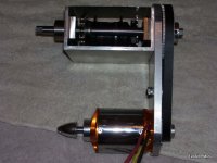
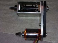
Catrike Three Speed

Not satisfied with the quality of the finish from the wood router bits (go figure :roll: )
I did a quick search and found these beauties from Amana tool.

I wish it was available with a 1/2" shank for stiffness...but it outta work much much better!!

router_template_bits_for_aluminum.JPG

spiral_aluminum_bits.JPG

Check it out Grinhill !
 
very nice...how many $$$$$? :mrgreen:
 
I see now that your pulley and mine are different. My 24 tooth pulley is a tad wider.

One of these days I may try one of those aluminum specific router bits, but at $60 - $70 per bit, I will stay with my cheep $20 WT Tool bits. I can live with ugly cuts. Matt said he uses a 3 flute bit for his work. He advised me that lower rpms and a lite finish cut is the way to a smooth finish.

I just noticed the shaft on my new motor is non-magnetic. Don't know if that is important when making a new one.

Things are looking good. Keep the pictures coming.

Bubba
 
Thanks for the encouragement Bubba.

re: Pulley width...
I was beginning to think that the shafts have varying lengths.... wouldn't suprise me.
So, I'm glad you pointed that out.

re: router bits
Yea, haven't priced the Al bits out yet, but they do sound pricey...

I'll have to really try to lower the rpms and see about that finish cut.
I could put an oversize bearing on the bit for the rough cut.
Then switch the bearing out for the correct size for the final cut.

Maybe I should try a 1/2" end mill for non-template work.

re: New motor
Hmm....sounds like a stainless shaft, 300 series...
Did the new motor come with a huge 55mm bearing on the firewall mount side
of the bell? It seems that the quality is getting better
A small problem is the longer length...no big deal though.

I found some excellent tubing clamps for low cost from MSC.
I'm gonna post those when I get to work.

I bought some cheap spokes from an ebay supplier. He has every size imaginable.
But, I worry about the quality vs DT Swiss...
I got 177mm 14ga for a 3 cross laceup on a 20" sun ringle rim.
DT swiss champion spokes are available in 176mm.
So, I think I'm gonna order those. However, I'm also a bit worried about the nipple
seat in the rim. With such a small rim and large hub, the three cross has
a large angle at the nipple seat. I have it laced, but haven't tensioned it yet,
since I'm contemplating replacing them anyway.

But, am I gonna run into tensioning problems due to large angle at the nipple?
 
re: nonmagnetic shafting

I'm not a motor expert, but I'd say that non-magnetic shafting is better in this case if
not in general. With an out-runner, you have a shaft spinning inside of a magnetic material, the stator.
If you have magnetic material shafting, it would have energy coupled into it that is possibly
robbing flux from the stator... Even with a non-magnetic shaft, you may have eddy currents
induced that rob a slight amount of power. The distance from the stator to the shaft
is significant, 1 cm or more from memory....therefore, probably not much power is being robbed
in either case.... I dunno... makes sense to me...

For these new AC drives and motors, a few companies sell a current drain adapter to the end of the motor
shafting and case to prevent high voltage buildup on the shaft that can arc through the bearings and cause pitting of
the races and premeture bearing failure. I don't understand all of the physics mechanisms that causes the build up
of charge on the shaft.... high frequency eddy currents due to pwm switching of 440 volts being passed through
the rotor?

anyway...

More pics...More parts....More fabrication

Steel Clamps with Alodine Coating or somekind of yellow protective coating.
Much, much stronger than the stamped steel sheet metal conduit clamps.
The elastomer makes an excellent round to square transition.
The main tube is 2" diameter.
It is not a soft squishy elastomer, it is somewhat hard but can be scratched with my
fingernail...
The flat wings on the clamp flanges seem to be 1/2" bolt holes...haven't measure them yet.
I am stoked!!

tubing_clamp_split.jpg

clamp_elastomers.jpg

drive_bottom_with_clamp.jpg

drive_mounts.jpg

And I'm just about ready to install the bearings in the sides...
I just need the shafting to help square and align the whole
assembly before I tack it down with hot glue and drill and tap all
the mounting holes for the bearing housing flanges.

The 15mm shafting (should have done 1/2") will be induction hardened, with flats spots for
the pulley and keyway for the sprocket. It will also have grooves for circlips
to retain the shaft centered between the bearings. It's overkill, maybe I'll
actually work out some design calcs on the next one...

bearings_drive.jpg

And just wait till you guys see my new badass motor t-shirt...any of
you Black Sabbath motor nerds will love it...

More to come...
 
12p3phPMDC said:
re: nonmagnetic shafting
I'm not a motor expert, but I'd say that non-magnetic shafting is better in this case if not in general. With an out-runner, you have a shaft spinning inside of a magnetic material, the stator. If you have magnetic material shafting, it would have energy coupled into it that is possibly
robbing flux from the stator... Even with a non-magnetic shaft, you may have eddy currents induced that rob a slight amount of power...
No problem, most/all of the magnetic flux is concentrated in/by the stator. And furthermore, there's an airgap between stator and shaft. Air has high magnetic resistance (= reluctance).
Have a look at the motor magnetic flux simulations (not the animations):
http://www.rcgroups.com/forums/showthread.php?t=216928


Prettig weekend ;) Ron
 
re: New motor
Hmm....sounds like a stainless shaft, 300 series...
Did the new motor come with a huge 55mm bearing on the firewall mount side
of the bell? It seems that the quality is getting better
A small problem is the longer length...no big deal though.

My new motor is an hxt 80-85 and it has the large bearing on the mounting side. My experience says that the QC on the motors has not improved. The setscrews holding the bell to the shaft were loose, several of the screws around the circumference were loose, and all four of the screws on the mount side were loose. All three of my motor had similar problems. Even with the problems, I still think they are good for the money.

Bubba
 
Chain Tensioners for the three speed.

They aren't the nicest chain tensioners...I had to tweak them a bit.
but they will work and they are small and out of the way,
and they were very inexpensive.

I think it looks clean.

torque_washer_disc_brake_output_side.jpg
View attachment 1
View attachment 2
 
Man it's feeling good to have a lathe mill combination machine up and running.
I built the bench for it and bent up a sheet metal catch basin for it to sit on..
I've been tuning it up and started to get more tooling for it. I have enough
to do some basic operations...which is awesome in itself!!

I made alot of progress on machining the rotating assembly today.

Between the mill/lathe and the drill press I was able to get a lot done...

-drilled and tapped all of the holes for the bearing assemblies.

- drilled all the holes for the motor and mounted it...

- reamed the pulley holes for the motor and the jackshaft.

- installed the 5mm 15mm wide Polychain belt and the bmx chain.

- milled the slot for the belt tensioner, installed the belt tensioner.
I need to the fabricate a tension adjustment bolt/sliding assembly

- upgraded the chain tensioners. I have enough adjustment for 1 link, so
I didn't need a half link.

The freewheel on the Shimano Three speed is very quiet.

I bought some new DT swiss champion spokes to do a 2 cross pattern on the wheel. 3 cross is too much with such a small wheel and a large hub. The nipple angle is too large with a three cross.

Tommorrow, I'll drill the hole for the tubing mounts and bolt this thing up to the trike
and try to finish/solve all the final mounting details.

The fabrication side is going pretty well.. I was able to get everything to bolt up nicely.
The holes are accurate enough that I didn't have to go to great lengths to get it all
to bolt up.
I used transfer punches to set the drilling patterns.
It not CNC perfect, but using drill rod to pin the assembly I only had to redrill a few holes
very slightly. So, it's all within tolerance...whatever that is...

:D

100_2013.JPG

100_2015.JPG

100_2016.JPG

100_2017.JPG

 
The left and right bearing blocks that support the jackshaft are off axis. This causes the jackshaft to bind.

Would self alignment style bearings help fix it? That would probably require self-alignment bearings on both ends of the shaft. I need some help with ideas on how to fix it. :|

I think I need a floating bearing block of sorts that I can bolt down in an unstressed position. I also think the hardened shaft is causing problems. It's too hard to get the
shaft in and out of the bearings, I think the heat treat process distorted the shaft I need to order some more shaft material. Ground drill rod? The shaft is a huge 15mm. Any ideas?? :idea:

100_2013.JPG

The bearing block is shown unbolted in this pic. The bearing block bolts from inside of the drive. I guess that I couldn't bore a straight line across the 135mm+ span across the drive housing.
Has anybody had to correct this sort of problem before?
tensioner_shifter_drive_side.jpg
 
Just a thought, but...

In hopes of using much of what you've already put a lot of time into, re-work the left side of the rectangular housing. I'd enlarge the circular hole that the round protrusion of the bearing block is inserted into. No way to recut it to fit now, if its off alignment compared to the right side. Might as well hog out something, and the left side seems to be the best candidate to salvage the rest of the drive housing.

Perhaps possible to fix the housing by re-working the right side, but it looks like doing that would be MUCH more involved and complex.

Once you're committed to doing that, I'd make a square end plate with a new circular hole that snugly fits the bearing housings circular part. Move the new endplate around until you're certain the bearing alignment is good now, and clamp it down. If further testing verifies it now works well, drill two opposing corner holes to really anchor it, for further testing.

It "looks like" the interior portion of the bearing housing on the left has a square flange. I assume it has four corner bolts? If yes, of course the bolts would have to be removed to allow the bearing housing to be slid around sideways to find the correct new alignment, but...once thats been accomplished (with the addition of the extra end-plate) the interior flange might be able to be rotated 45 degrees to find fresh housing to drill 4 new anchoring holes?

This is a wonderful project, best of luck!
 
Figure out which way the bearing assembly needs to move and oval out the holes about 1/8” in that direction. Use through bolts from the outside to the inside. It looks like you have enough space for some nuts on the inside. You could do without the nuts if you go to a larger bolt and thread your inside bearing support flange.

Heat treating can warp the shaft. I have used drill rod and did the heat treating myself. It took me several tries to get one that did not warp. Polish your shaft to remove all of the deposits left by heat treating. I put mine in the drill press and used scotch bright until it was shinny again.
Plain drill rod works fine without heat treating it unless your bearing are running directly on the shaft. Flats on the shaft seem to make disassembly easier because any burrs from the set screws are out of the way of the sliding surfaces.

Bubba
 
Hello, If I have your setup in my mind correctly here's how you could fix the problem easily. Make a new bearing block for one (or both) sides and leave the holes the bearings fit into a bit small say 1/16 inch. Clamp the channel, with the new blocks installed, to the topslide of your lathe using shims for height and aligned to centers in the headstock and tailstock. Mount a boring bar between the centers and bore the bearing blocks to size. Setup takes a bit of time but the holes will be straight :D .
 
The method that you are using with applied bearing blocks is very tolerant of mistakes, so you are lucky there.

However, bolting it from the inside is very difficult to work with. I would bolt them on the outside.

Bubba's got the best idea (well, boring it out on the lathe is the best idea, but Bubba's is almost as good, and much faster).

If you enlarge the shaft hole so that you can move the bearing holder around (shaft hole size doesn't matter anyway, bearings doing all the work) then you can find out where the bearing block wants to sit.

Once you have a good idea roughly where the little fella wants to be, then clamp it there somehow and turn the shaft to see if it runs nicely.

If it runs nicely, use your transfer punches (good you have those, btw) and bolt it down. I'd use through bolts unless you are dead sure you have the alignment right. Through bolts will give you a mm or so to play with.

JMHO,

Katou
 
thanks for the advice, I think that I will try a combination of things.

-Oval the hole slightly trying to retain enough clearance to the holes.
-Precision Drill rod
-rotate the housing 45 and drill/tapping new holes.
 
A way to clamp them in place to test-fit:

drill new hole in bearing block (making 5 total)
drill corresponding hole, but oversize
through-bolt with oversize washer to cover oversize hole
tighten bolt gently
tap block in any direction with hammer to micro-adjust position until shaft runs true and easy
drill holes for remaining bolts and tighten
remove extra bolt


BTW, how the heck are you drilling those holes? How do you mark to drill them? I don't know how to do that from the inside.

Katou
 
Katou,

First I bored the clearance holes for the double bearing blocks. This was probably the original source of error.
IFIRC, I drilled a pilot hole and tried to transfer it from one side to the other. I should have used a long piece of drill
rod, and a machinists square to keep the pilot holes aligned.

I installed the driven side first using the bearing block to transfer the holes using transfer punches.
Then I installed a temporary shaft in the driven block which was bolted down, and in the opposing bearing block
which was floating. I then flipped the bearing block so that the mounting the bearing block holes were on the outside.
I tried to tack the the bearing block down in it's natural position with hot glue as a fixture. I used transfer punches,
and set the hole pattern, but something went wrong.

I like the idea you proposed....


And spinningmagnets, thanks for the encouragement... I'm ready to get back into it and get it finished!
 
So you drilled from the outside... Hmm, okay, I see. The initial pilot hole set the accuracy for all subsequent steps.

The shaft clearance hole went off the pilot hole.

Bearing blocks got set off the clearance hole... Wait, I think that's the source of your error. You did one side, marked, drilled, bolted and THEN the other right?

The clearance hole is bigger than the shaft (has to be) so anything that goes off that will have some small error. Shafts with regular bearings are very intolerant of misalignment, even 0.005" out of square, no go.

If the bearing blocks are set in position WHILE ATTACHED TO THE SHAFT you can check for binding. But BOTH have to be on the shaft, and both have to be clamped to the housing.

If you do one, then the other, they will always end up a bit off.

So, there are two possible sources of error here.

JMHO,

Katou
 
Back
Top