Cell log HVC relay for bulk charging

auraslip

10 MW
Joined
Mar 5, 2010
Messages
3,535
It's been covered to death, but I'm only familiar with how it would work and not the exact parts needed to implement it.
I'll be using a power supply to charge a 16s ping, so it'll be 2 cell-logs in series.
Perhaps the best way to implement it would be so it latches off? This would prevent it from flip on and off all night. Another option is a light timer that shuts off in X hours. Right now I'd like it to keep the cells from over charging!
file.php

PIC by AMBERWOLF!
I assume it will be a bit different though because it will be in series.

CNY 17F optocoupler

4.7k 1/4w resistor

1k-10k 1/4w resistor? What should the actual rating be?

NPN small signal transistor?

1n914 diode?

24v coil relay - contacts rated at 120v 20a (over kill?)
Why DPDT? Why not just spst?

.5a fuse - not sure what this is for?

Some sort of project board and box to put it all together on?

Sorry for all the noob questions. I'm a bit sick right now and stressed out about studying for finals, so my brain isn't working right. On top of that my bike is my only transportation, and since I've been using it to mow lawns it's my only source of income too! I've got all the tools to do this, but this will be "babies first circuit."


I uploaded the tiny cad file as a pdf. Rename it to a .dsn file to edit it with tiny cad.
 

Attachments

  • ping-celllog-relay.pdf
    27.3 KB · Views: 185
It's been so very long that I don't remember what any of the stuff left of the buzzer is for; that is all someone else's circuit; all I did was add the stuff on teh right that theoretically should just switch the charger AC power off at HVC. ;) Unfortunatley I have no idea what thread that was from, or you could look there for the original circuit and explanations of it. :(

I expect the fuse is there so that should something fail on the DC side, that it'll blow the fuse rather than kill your battery.


Keep in mind that hte transistor shown is based on teh battery being a lower voltage, liek teh 24V one shown. You'd need suitably higher voltage "small signal" switching transistor for higher voltages, and probably resistors in series with emittor or collector of the transistor, to limit current thru the relay coil since the relay is a 24V coil (or just get a relay with a coil voltage of similar rating to your pack at hot-off-charger voltage).

ALso resistor in series with the buzzer, since it's a 24V buzzer listed, too. If you don't care about an audible warning you can just leave the buzzer out.

base resistor 1k-10k value would be determined by how much current you need to switch on the transistor fully, without cooking it. Depends on the input voltage.

DPDT was probably because it's often easier to find those just lying around in stuff. :) DPST is probably al that's needed (cuz it's safer to switch both hot and neutral off, but you could switch just the hot off, if you want, with SPST. )


Regarding the second circuit diagram, you show two relays, but it only needs one, assuming you are doing a circuit like the first one. You just wire up all the optoisolator open-collector outputs to the same point, and run the buzzer/relay off of that. Each Cellllog gets it's own opto, but that's all that's needed.

If the celllogs can output enoguh current to directly switch the relay coil, then you could use relays directly on them as in the drawing, but probably they can't.

I'm pretty sure I've seen a better drawing than mine somewhere else in a thread about multiple celllogs (prbably one of the F/G BMS dev threads) for use with multiple cellogs and such.

Whatever circuit you use, you can test each half separately to be sure they work. In fact, you can include a "charger shut off" button that turns on the relay, if you like, so you can A) test it adn B) have a "kill switch" of sorts.


An alternate version that would only draw power from the charger itself rather than the battery (for the relay and transistor), and would swtich the relay *off* rather than on at HVC, would probably be better. But I am having trouble thinking at the moment and can't come up with a diagram. I do know you'd want to run the charger's DC side and relay coil thru the relay as well as it's AC side so that it would latch the relay on until the transistor was shut off by the HVC signal, but can't picture this right now.

It's been done before, and uses a pushbutton momentary switch to "bootstrap" the transistor on from teh charger power for the simple version, or a rectifier/RC circuit for automatic turn on (I think).
 
Amberwolf - thanks. here is the thread I nicked the picture from. I followed your advice about having the charger power the relays. Here is a new diagram using two NO relays and a NC relay and a MO switch.

When you press the momentary switch the normally open relays latch open. When the cell log alarm triggers, the normally closed relay opens and the connection is broken. Without the momentary switch the NO relays won't latch.
The trick is finding 10a relays rated at 60vdc and higher!

Also - everything else.
 
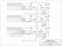
Below is the CellLog circuit I use. It isolates the CellLog alarm outputs to generate an opto line that is equivalent to a combined LVC/HVC signal, like we use in the various charge controller implementations. This signal can be used to pull down the throttle signal, in an LVC mode, and to "throttle" the charge current in a suitable charge controller, either the one used in the new BMS, or with one of the MeanWell charge controller widgets.

In order to use the CellLogs on the bike, I needed a way to turn them off, so I added an "Enable" line that uses a small DIP-sized relay to turn on power to the CellLogs.

Anyway, here's the schematic:

3x8s CellLog HVC-LVC-v4.3.5b.gif

You don't really want to simply cut power to the supply when a cell first hits HVC. It is better to use the HVC signal to cut the supply current down, to where the cell(s) are not going over the limit. That way the cells will get fuller.

-- Gary
 
Thank you Mr. Gary the ebike wizard.

The new charge boards seem like a much better option than a bunch of relays.
I can't wait to order the new boards and put them together!


Looking at your schematic, am I to think that most of it is for switching the cell logs on and off? I only need a resistor and opto coupler per cell-log to get the throttling functionality with the new charge boards? I suppose I should just build your lvc-hvc parallel boards, but this is for a temporary build and it's already wired up for 8s. I just need something quick!

Thanks again!
 

I know this isn't ideal, but it's cheap, easy, and I can figure it out. I researched optocouplers for a bit, but could piece together what I needed.
24vdc relay spst NO 16ma coil draw - $1 x2

120vac spdt relay $6

For the 120vac relay, should the coil be connected to earth or signal ground?

Another option would be to use a 60vdc relay, and then I could rig up an lvc to go along with it.
 
Back
Top