llile
1 kW
- Joined
- Dec 18, 2010
- Messages
- 457
Got 3 Mean Well NES-350 power supplies and hacked them into a charger. Some modifications were in order.
The NES-350 series is a constant current - constant voltage power supply series much like the venerable S-350 that so many people use for a charger. Voltage is adjustable, current is not adjustable without a hack. They are fan cooled. They can be found for as little as $30 apiece on Ebay.
Here is my instructable covering the same ground, with somewhat better \pictures.
In order to make up a ~1000 W power supply capable of delivering 82.4V max DC, it takes three supplies. Two 24V and one 27V. I'm using 82.4V because that is a recommended float charge voltage for a 24S battery - one could charge at higher voltages but it would not be good for the battery to leave the charger on too long.
These supplies are not adjustable current, and there is no handy R33 hack to adjust the maximum current. These supplies use an LM3845 Current Mode Controller as the heart of the power supply. This chip compares the voltage drop across a fixed sense resistor to a 1.0V internal reference, instead of a voltage divider, to set the maximum current.
Fortunately, the fixed sense resistor is easy to identify. It consists of two prominent thick jumper wires, standing about 1cm off the board, near the power terminals. A key indicator is these resistors show nearly 0 ohms to the negative power supply terminal - and the LM3845 datasheet indicates that it's sense resistor is to be connected to the negative supply.
The rated max current on the NES-350-27 (27V version) is 13 amps. I had to turn the voltages to 25 - 25 - 32.4 volts to achieve my 82.4V output. At 32.4V and 13 amps, I would be producing 421 watts at the higher voltage supply, enough to maybe burn it out or cause it to go into thermal shutdown. The current must be adjusted down to make it stay within power rating specs. The two 24V supplies, adjusted to 25 volts output, would be within safe limits at such currents.
Since there are two sense resistors, a simple way to cut down on the output current is to snip one of the resistors. This cut the max current in half. I made up a 2 ohm high power resistor load out of some nichrome wire and ceramics I had laying about to test the idea. Sure enough, with a load, I could produce 12.5 amps max, but with one sense resistor cut, only 6.25 amps.
What I'd really like is about 11 amps output. 10.8A *32.4 volts = 350 watts, just within the power supply spec. After playing around with the sense resistors a bit, I realized that soldering a 6" length of #22 wire in place of one resistor adjusted the max output current nicely to just under 11 amps. Total output isn't quite 1000W, more like 880W, but still pretty fast compared to a typical 3 or 5 amp charger. I'm on 40AH LiFEPo4s, so they can take the higher charge rates with no problem.
Then I had the bright idea of putting a switch in the middle of this 22 ga wire. Switch closed - fast charger 11 amps. Switch open - slow battery-pleasing charger 6 amps.
Another issue is surge at plug-in. Often I am charging not at home - and I am begging for the privilege. The last thing I want to do is to beg for a charge on the road, then go back and tell them I popped their GFI or a breaker. These power supplies will dim the lights for a quarter second when you plugged them in. Three of them, per the datasheet, have the potential to create a 40 amp surge each when plugging them in - 120 amp surge! They dim the lights on my electronics bench, and will often pop a ground fault receptacle on a false trip. Good luck then, Charlie, ground fault receptacles only work about 80% of the time after they trip in my experience. I find them failed all the time at parks and public spaces, two have failed on my own house.
I hacked up a power switch that has a Three-position on-off-on switch. Center is off. In one direction, there are two 5 ohm 5 watt resistors in series with the hot and neutral lines. In the other direction, the hot and neutral are connected on, just like a normal switch. I have some other devices set up like this and it has worked out well. The power supply doesn't care, but the initial surge is minimal with these 5 ohm resistors in line. The direction with the resistors is spring loaded, so it cannot be left on in that direction without holding it. Charge for a few seconds, then kick it to ON.
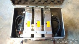
Here are some photos of the results, hacked into a Makita tool case box which will have to remain open during charging to allow the fans to work:


View attachment 2
The NES-350 series is a constant current - constant voltage power supply series much like the venerable S-350 that so many people use for a charger. Voltage is adjustable, current is not adjustable without a hack. They are fan cooled. They can be found for as little as $30 apiece on Ebay.
Here is my instructable covering the same ground, with somewhat better \pictures.
In order to make up a ~1000 W power supply capable of delivering 82.4V max DC, it takes three supplies. Two 24V and one 27V. I'm using 82.4V because that is a recommended float charge voltage for a 24S battery - one could charge at higher voltages but it would not be good for the battery to leave the charger on too long.
These supplies are not adjustable current, and there is no handy R33 hack to adjust the maximum current. These supplies use an LM3845 Current Mode Controller as the heart of the power supply. This chip compares the voltage drop across a fixed sense resistor to a 1.0V internal reference, instead of a voltage divider, to set the maximum current.
Fortunately, the fixed sense resistor is easy to identify. It consists of two prominent thick jumper wires, standing about 1cm off the board, near the power terminals. A key indicator is these resistors show nearly 0 ohms to the negative power supply terminal - and the LM3845 datasheet indicates that it's sense resistor is to be connected to the negative supply.
The rated max current on the NES-350-27 (27V version) is 13 amps. I had to turn the voltages to 25 - 25 - 32.4 volts to achieve my 82.4V output. At 32.4V and 13 amps, I would be producing 421 watts at the higher voltage supply, enough to maybe burn it out or cause it to go into thermal shutdown. The current must be adjusted down to make it stay within power rating specs. The two 24V supplies, adjusted to 25 volts output, would be within safe limits at such currents.
Since there are two sense resistors, a simple way to cut down on the output current is to snip one of the resistors. This cut the max current in half. I made up a 2 ohm high power resistor load out of some nichrome wire and ceramics I had laying about to test the idea. Sure enough, with a load, I could produce 12.5 amps max, but with one sense resistor cut, only 6.25 amps.
What I'd really like is about 11 amps output. 10.8A *32.4 volts = 350 watts, just within the power supply spec. After playing around with the sense resistors a bit, I realized that soldering a 6" length of #22 wire in place of one resistor adjusted the max output current nicely to just under 11 amps. Total output isn't quite 1000W, more like 880W, but still pretty fast compared to a typical 3 or 5 amp charger. I'm on 40AH LiFEPo4s, so they can take the higher charge rates with no problem.
Then I had the bright idea of putting a switch in the middle of this 22 ga wire. Switch closed - fast charger 11 amps. Switch open - slow battery-pleasing charger 6 amps.
Another issue is surge at plug-in. Often I am charging not at home - and I am begging for the privilege. The last thing I want to do is to beg for a charge on the road, then go back and tell them I popped their GFI or a breaker. These power supplies will dim the lights for a quarter second when you plugged them in. Three of them, per the datasheet, have the potential to create a 40 amp surge each when plugging them in - 120 amp surge! They dim the lights on my electronics bench, and will often pop a ground fault receptacle on a false trip. Good luck then, Charlie, ground fault receptacles only work about 80% of the time after they trip in my experience. I find them failed all the time at parks and public spaces, two have failed on my own house.
I hacked up a power switch that has a Three-position on-off-on switch. Center is off. In one direction, there are two 5 ohm 5 watt resistors in series with the hot and neutral lines. In the other direction, the hot and neutral are connected on, just like a normal switch. I have some other devices set up like this and it has worked out well. The power supply doesn't care, but the initial surge is minimal with these 5 ohm resistors in line. The direction with the resistors is spring loaded, so it cannot be left on in that direction without holding it. Charge for a few seconds, then kick it to ON.
Here are some photos of the results, hacked into a Makita tool case box which will have to remain open during charging to allow the fans to work:
View attachment 2