Components identification and Specialized Turbo 2015 repair

Consider running a VESC as a controller ( it will run anything ).. it does sensorless mode with some low end torque loss being the worst of the compromises you'll make by doing so.

The battery is 9 years old and likely very saggy/crappy by now.. i'd consider gutting the pack and adding on a triangle pack with

..basically i'm saying, instead of working with the existing electronics, consider bypassing all of them, it's more headache than it's worth to fix them.
 
Consider running a VESC as a controller ( it will run anything ).. it does sensorless mode with some low end torque loss being the worst of the compromises you'll make by doing so.
thanx for this info. i looked at d VESCs, very interesting. but for my current project they seem an overkill, both power&moneywise. smallest i see, VESC 6 MkV, does 80A continuously, that's 10x d output i need!

The battery is 9 years old and likely very saggy/crappy by now.. i'd consider gutting the pack and adding on a triangle pack with

..basically i'm saying, instead of working with the existing electronics, consider bypassing all of them, it's more headache than it's worth to fix them.
as you suggest, i am actually trying to get rid of original electronics; i changed d BMS (which seems to be source of trouble) and am now looking for a controller & screen.
battery, sure, not new, but cell-V (3.98V) hasn't dropped in 1.5years i've had it standing around - i suspect bike has been used very little so i want to first keep it and see.
 
battery, sure, not new, but cell-V (3.98V) hasn't dropped in 1.5years i've had it standing around - i suspect bike has been used very little so i want to first keep it and see.
Remember these batteries also degrade chronologically over time even with little or no usage. Simply testing voltage drop over time is not a good indicator of battery condition. Not saying you should immediately condemn it but it may in fact be seriously degraded after 9 years even if it seems to be holding voltage.
 
Remember these batteries also degrade chronologically over time even with little or no usage. Simply testing voltage drop over time is not a good indicator of battery condition. Not saying you should immediately condemn it but it may in fact be seriously degraded after 9 years even if it seems to be holding voltage.
agreed. i just wanna see if i can even get bike working again. essentials first.
before i rip it apart and integrate good cells into my powerwall :)
 
You will have to strip out the PCB to connect an external sensorless controller.
before i go ahead with ordering this controller, i've been searching around to understand this hall-sensor (HS) issue - i'm afraid i still don't know much. please someone can enlighten me?

why are most (it seems) motors still using HS if it works without? they must add complexity. is it because
  1. more precise?
  2. better control?

HS-less:
  1. is this a new 'thing'?
  2. if no HS, must d controller be a 'square-wave' type?
  3. do these controllers sense d position of rotor in a different way (square wave?), or no need anymore?

The hall sensors in the motor are 2 linear halls in sine/cosine arrangement close to the central hub of the motor. There is a third one for patented torque sensing by deformation.

not much else near hub that resembles a HS - is this 1? see picture.
how many does a 3-phase motor need, at least 3?
 

Attachments

  • motor6.jpeg
    motor6.jpeg
    163.8 KB · Views: 7
Check out this pic, the Hall sensors I meant are the ones that stand in a circular pattern towards the shaft, right from the processor...

just to be sure: the ones i circled on my pic?
i thought halls are always very close to mags in order to be effective (these don't seem to have a 'counterpart'). at least it was like that on d 5kW GM i once opened.
doesn't it need at least 3 for 3 phases? evenly spaced?
 

Attachments

  • motor7.jpeg
    motor7.jpeg
    299.1 KB · Views: 5
just to be sure: the ones i circled on my pic?
i thought halls are always very close to mags in order to be effective (these don't seem to have a 'counterpart'). at least it was like that on d 5kW GM i once opened.
doesn't it need at least 3 for 3 phases? evenly spaced?
You're 100% right. The motor you own has a separate sensor magnet ring at the central hub. All of the halls are linear ratiometric elements, the two outer ones give sine/cosine info, the inner one can measure torque by how much the central hub twists inside the motor. This all works completely different from the common setup with 3x switching hall sensors.

Br, Thomas.
 
surfing on Aliexpress it seems that ebike-motors have hall-sensors but electric scooters don't; is this a fact and why would that be?
 
Sorry, I can't help you with this one... I have no market overview, I'm more into deepdiving through the system I have at hand. I just happened to have the same motor :)
no worries, i'm asking everybody. a rather important subject in order to understand how things work i'd say. i'll try again:

why are most (it seems) motors still using HS if it works without? they must add complexity. is it because
  1. more precise?
  2. better control?

HS-less:
  1. is this a new 'thing'?
  2. if no HS, must d controller be a 'square-wave' type?
  3. do these controllers sense d position of rotor in a different way (square wave?), or no need (except for some features)?
 
Hall sensors give the controller precise timing information at zero speed so startup from a dead stop always works properly. Sensorless systems rely on the motor to be moving to get the timing information. At a dead stop, it has to "guess" and tries to get the motor moving the right way. This can result in bad startup behavior. With a kick scooter, you're usually pushing off with your foot at startup to give the motor some speed before the controller kicks in.

Hall sensors will work well in all situations but sensorless sometimes does not, especially with high loads, like trying to start out on a steep uphill.

There are more advanced sensorless systems that can detect rotor position at a dead stop, but these are not the kind you typically find in a cheap scooter.
 
With a kick scooter, you're usually pushing off with your foot at startup to give the motor some speed before the controller kicks in.
oh good, than it should work on my bike; it also takes a pedal to move past a sensor to get motor going. i shall order a 'sensorless' controller now :)
 
ok, some progress: i removed original controller and soldered 3 wires directly to d 3 phases of motor. i wonder, how to connect them to d 3 phases of new controller output, what is d right sequence? yellow-green-blue wires on d left of controller-picture.
or connect them any way, if motor kind of just vibrates, then try a different connection? can something be damaged?
which of d wires could be throttle control? on far right, hidden in a black hose, is plus/minus battery connection.
 

Attachments

  • wires motor-2.jpg
    wires motor-2.jpg
    593.4 KB · Views: 5
  • wires controller.jpg
    wires controller.jpg
    554.2 KB · Views: 5
ok, wheel spins, can control speed :bigthumb:
spins a bit fast b d look of it, maybe bcoz d controller is for an e-scooter? that should help to break speed-limit :D or burn motor.
now to properly assemble this wheel again, seems like an 'exercise in patience'. spokes all back, it's wobbling along severely :sneaky:
 
tests show following:
theoretical speed (wheel off d ground): 54km/h
speed on flat road = 37km/h.
only small inclinations can be handled without pedal assist.
controller (19A) is just a little bit warm.

can't measure A while riding, but i'd say no 5A flowing, wires remain cold.
how could it be forced to give more power?
any suggestions how to improve uphill performance?
 

Attachments

  • fix1.jpeg
    fix1.jpeg
    168.4 KB · Views: 5
  • fix2.jpeg
    fix2.jpeg
    91.1 KB · Views: 5
PS
I bought bike already broken, so don't know original performance. motor looks quite big, although sticker says only 200W - possibly 'detuned'?
i can't imagine anybody would've spent €4000+ on this bike if it wouldn't fly uphill. in switzerland ;)
 
i understand increasing V would speed motor up. but i think i'm not lacking rpm, but torque - would that be Amps?
just theoretically, how much more V can a motor handle, what is d limiting factor? overrevving? insulation of copper wires? i understand Amps are limited by wire cross-section, but V ?
 
To get more torque, you want more amps. Increasing voltage will make the motor spin faster and will increase the torque slightly as the total power going to the motor will be more. Heat is the limiting factor.
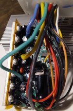
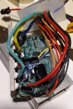
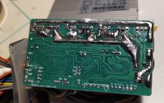
To get more amps out of the controller, you likely need a new controller or you might be able to modify your existing controller. Some models are programmable, but most of the cheaper ones are not. The amps can be increased by lowering the resistance of the current measuring shunt inside the controller. If you take apart your controller and take some pictures of the board, I can probably point out where the shunt is.
wow, exciting, tuning a controller :cool:
are attached pics any good?
 

Attachments

  • WhatsApp Image 2024-11-19 at 18.35.54(2).jpeg
    WhatsApp Image 2024-11-19 at 18.35.54(2).jpeg
    177.6 KB · Views: 9
  • WhatsApp Image 2024-11-19 at 18.35.54(1).jpeg
    WhatsApp Image 2024-11-19 at 18.35.54(1).jpeg
    217.3 KB · Views: 9
  • WhatsApp Image 2024-11-19 at 18.35.54.jpeg
    WhatsApp Image 2024-11-19 at 18.35.54.jpeg
    243 KB · Views: 9
  • WhatsApp Image 2024-11-19 at 18.35.53(1).jpeg
    WhatsApp Image 2024-11-19 at 18.35.53(1).jpeg
    271.9 KB · Views: 9
  • WhatsApp Image 2024-11-19 at 18.35.53.jpeg
    WhatsApp Image 2024-11-19 at 18.35.53.jpeg
    255.9 KB · Views: 9
1732117785786.png

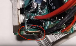
That's a pretty typical old school cheap controller. The current measuring shunt is a piece of Manganin wire (circled in red).
To increase the current, the resistance of the wire needs to be decreased. What people used to do is solder a small piece of copper wire from one end of the shunt to somewhere in the middle. If you lower the resistance too much, the controller might blow up from too much current. It's kind of trial and error.

Another way is to trace out where the signal goes. On the left side of the shunt, I see a trace that runs under the black 50v capacitor. If you trace where that goes, it may be possible to solder in a pot to make the current adjustable.

Either way, you want to have some way to measure the current after making a change. If you can read the numbers on the FETs, we can get an idea for how much it can take without blowing up.
 
Another way is to trace out where the signal goes. On the left side of the shunt, I see a trace that runs under the black 50v capacitor. If you trace where that goes, it may be possible to solder in a pot to make the current adjustable.
thanx for d tip!
would it be possible to directly replace d shunt with a pot?
 
Back
Top