• Hello ES! We could use some help to get us past the finish line on building the new knowledgebase for the forum.
    Can you donate? Please see our fundraising page. Thank you!

Controller recommendations for torque sensor and regen braking

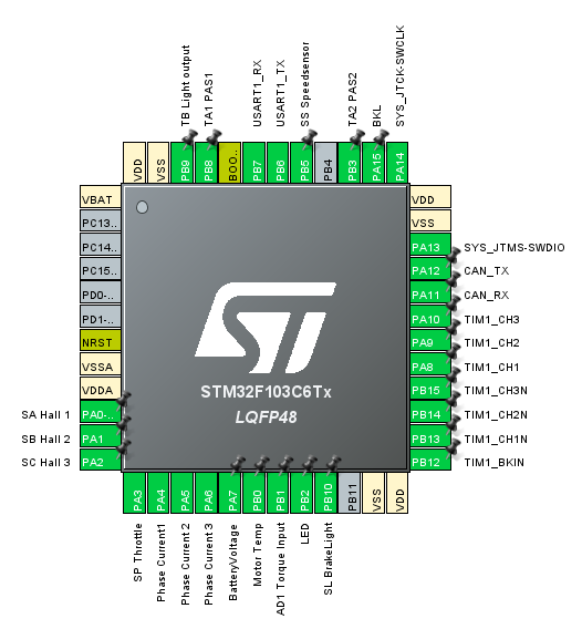
Lishui uses strict processor pin definitions. The processor pins are routed to solderpads on the PCB. Not all solderpads are wired normally, as the customer orders. If a wire is missing, you can solder it in, but you have to remove the potting....

Pinout%20New%20Generation.PNG
 
Thanks, I saw that pinout in your Github wiki already but I can't make sense of all the pin defintions. If the pins are strictly defined, would two throttle signals even be possible?
 
If the pins are strictly defined, would two throttle signals even be possible?
There are three analog inputs available for external signals. Throttle, temperature and torque. The temperature channel has a pull up resistor that has to be removed, if you want to use the pin as throttle input.
 
It took much longer than I thought to get everything working more or less. I now have a controller from Phoebeliu EV Parts but it doesn't have all the connections I need yet. I wanted to try it with the stock firmware a bit and then open it up to add new connectors and flash the open source firmware.
Right now I have to motor with hall sensors and the torque sensor connected to the controller. I had to change the phases around a few times until I got it to turn and move forward. I took it for a ride yesterday and noticed that the display doesn't show the speed even though the display settings should be set not to rely on an external speed sensor. Also it randomly starts recuperating when I'm not pedaling.
Is there a way to run the autodetect routine of the controller without having the dedicated pins to short that many controllers have? Or do you think my issues aren't related to this at all?
 
had to change the phases around a few times until I got it to turn and move forward.
?! Why? Just start the autodetct once, it will find the right commutation automatically. If the motor spins in the wrong direction, you have just to change the direction flag in the config.h....

Have you forked the EBiCS repo and have you committed your recent settings? Then I can take a look directly.
Otherwise post your main.h and your config.h

Or have you not tested with the OSF yet? I can't help with the stock firmware. Lishui provides customer specific firmwares normally.
No I have not flashed the OSF yet. I wanted to ask if you had any idea how to start the autodetect with the stock firmware because I have not found anything about that but if you also have no idea I'll start working on EBiCS
 
The stock firmware has no autodetct, as it is made for a certain hardware setup, everything is hard coded.
Ah I see. I thought I saw some lishui controllers that had two pins you had to short to start autodetect.
I'll get working on EBiCS then, I already got an STLink but didn't open the controller yet
 
Thanks for that, but I'll need to solder some new connections and clean up the connectors anyway
 
So I was able to build the firmware with default parameters now and I'm getting ready to flash. I'm using Linux so I can't use the flash utility that's suggested in your Github wiki. Do you have experience with stm32cube (apparently the successor) or this open source stlink utility?
Would you suggest flashing the default config initially or should I try to adjust things to my setup right away?
 
@stancecoke can you help me to flash it on Linux or is that not supported by you? I found this which seems to be the predecessor of your firmware and quotes your work in many places but I could not figure out what to do exactly yet.
Right now I have to board powered up and I connect to it in the stlink-gui program of the open-source utility I linked. But I'm not sure about disabling write protection and what file I would even flash. Is it one of the EBiCS_Firmware.bin/.elf/.hex files in the build directory or do I need to do something else after running make?
If it's too much trouble I could set up Windows for building and flashing
 
Sorry I've missed your post from Thursday.
I never used the Linux flash tools, but in the Readme of the repo, there is the recommendation to install them by the Linux distribution sites directly.

Linux / Unix:

We recommend to install stlink-tools from the package repository of the used distribution
 
Sorry I've missed your post from Thursday.
I never used the Linux flash tools, but in the Readme of the repo, there is the recommendation to install them by the Linux distribution sites directly.


Thanks, I already have it installed and it seems to be able to connect to the device. My controller uses an STM32 clone by Geehy called APM32F103C8T6
What file should I try to flash? Then I'll try getting st-flash to work
 
Yes, just try it.
But of course, it is possible, that.the recent hard coded hall angles doesn't fit to your setup. Then you have to disable the fixed angles and run the autodetect once. Good luck!(y)
 
Yes, just try it.
But of course, it is possible, that.the recent hard coded hall angles doesn't fit to your setup. Then you have to disable the fixed angles and run the autodetect once. Good luck!(y)
Thanks but I still don't know which file the actual firmware is. Is it EBiCS_Firmware.bin?
 
I use the .hex file normally, as it contains the address information already. With the bin you have to specify the start address in the flash command.
So now I was able to unlock write protection using stm32flash and I could successfully flash it with st-flash
I'm now working on cleaning up the connectors and adding the ones I need. I need a throttle that I need to solder to the SP connection if I understand correctly?
I also wanted to add an input for another throttle to control regen braking and you mentioned earlier that there was a third analogue input that's used for a temperature sensor. Afaik the white cable on the hall sensor cable is used for that? The other cables go to SA, SB, SC, GND and 5V and the white cable is connected to SS1. Would this be the correct pin?
 
No this is a digital input for the speed signal. You need the pin labeled with "Temp".
What's that one usually wired to inside the motor? I thought the speed was determined using the hall sensor signals
Ah, I found it, it was still covered under some pieces of silicone
 
What's that one usually wired to inside the motor? I thought the speed was determined using the hall sensor signals
Most hubmotors are geared motors with freewheel nowadays. If you are coasting or riding without assistance, you get no signal from the motorhalls. So there is an additional hall, that sends 6 pulses per wheel revolution normally.
 
Most hubmotors are geared motors with freewheel nowadays. If you are coasting or riding without assistance, you get no signal from the motorhalls. So there is an additional hall, that sends 6 pulses per wheel revolution normally.
Ah, I'll have to check if my motor even has that. I wanted to open it up at some point anyway
 
?! I would prefer a standard bicycle thumb- or half grip throttle, or a break lever with linear output. Why do you want to use something strange, like shown in your link?!
Because I want to actuate it with a thumb shifter that stays in place when I'm not holding it. That thing was the only thing I could find that would work like that
For acceleration I have a regular thumb throttle
 
Last edited:
Back
Top