Converting a carbon fiber THYS 209 Rowing Bike to Electric

justin_le

Administrator
Staff member
Joined
May 28, 2007
Messages
2,310
Location
Vancouver
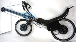
Here's an opportunity that doesn't show up every day. A customer emails asking if we can help him electrify his rowing bicycle. I've secretly always wanted to try riding (rowing) a rowbike. He offers to ship us his rowing bike from Europe so that we can do the full conversion here and fully field test it before sending it back. Yehaa!

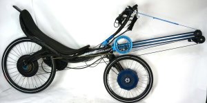
In this case, the vehicle is the THYS-209, carbon fiber construction recumbent rowing bike from rowingbike.com.
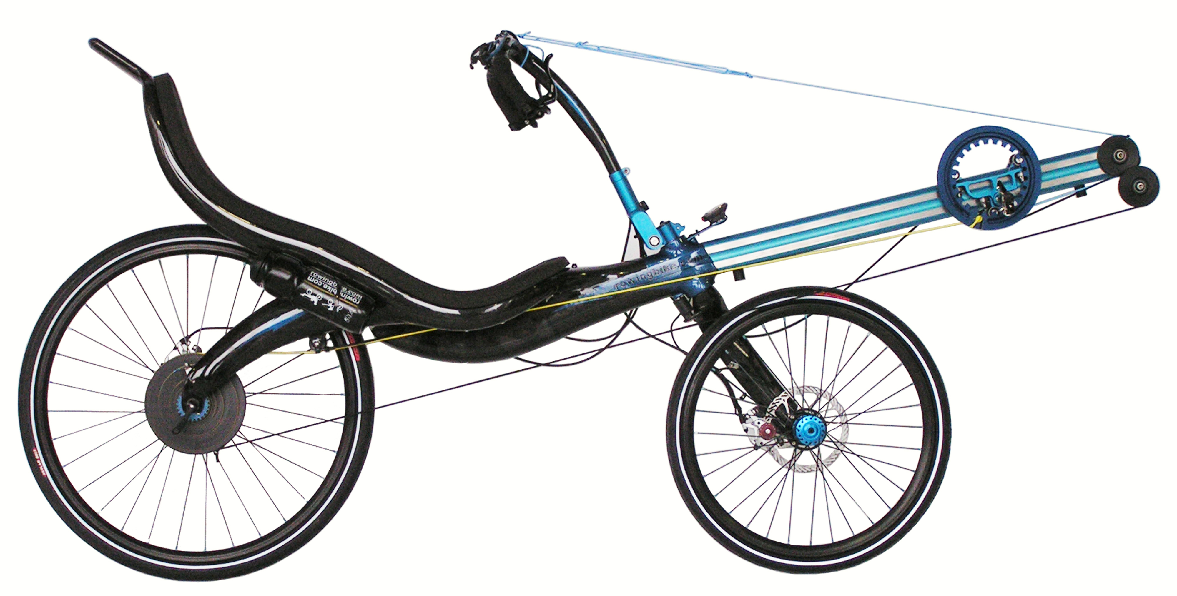
209_hi_res._1_procen_geel.jpg

https://rowingbike.com/en/product/thys-209-carbon-roeifiets-2/
and to see in action: https://rowingbike.com/en/media/videos/

The rear wheel is a completely custom hub with a large spiral groove machined down the side that a string wraps around, and a genius little mechanism allows you to change the effective gearing by pushing a lever during the rowing stroke which can wrap or unwrap more or less string from this, modifying the average diameter during the stroke.
Rowingbike Snek Gear.jpg

Part of the reason that the customer was interested in electrification is that on steeper hill climbs it's difficult to maintain sufficient velocity on a rowing bike to stay stable during the recovery stroke. You move forwards with pulses of thrust followed by a coasting period, and you don't coast very far when going up a steep grade.

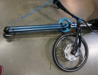
One big challenge, the front carbon fiber fork is single sided, like a cannondale lefty without the suspension. The front hub has a 17mm shaft going into a steel insert in the fork. That left the Grin All-Axle hub motor as our only potential conversion option, assuming we could machine some custom axle adapters to go from the 20mm thru axle to the 17mm single side mount on this fork.
 
Very interesting bike. That must be some kind of "string" that transmits the combined power of the riders legs and arms to the rear wheel.
 
richmpdx said:
Very interesting bike. That must be some kind of "string" that transmits the combined power of the riders legs and arms to the rear wheel.

Yes, It's an amazingly strong material with basically zero stretch at all. From what I can glean from the rowingbike.com page it is this Dyanmee material here
http://www.dsm.com/products/dyneema/en_GB/technologies/dyneema-form-factors/fiber.html

Test vs. Steel
https://www.youtube.com/watch?v=cYEMT5avIUk
 
Voltron said:
That seems like it might be a good job for a friction drive with the low tread tires and low power requirements...

That would actually be a decent suggestion here. But in this case the customer wants to be able to use it for long distance (300+ km/day) touring in areas like the alps with steep hills. I think a friction drive in that would be pushing the limits for tire wear and rolling traction on the hill climbs at the powers needed for that.

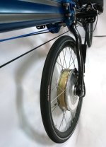
Anyways the original front wheel looks like this.
Rowingbike Front Wheel.jpg


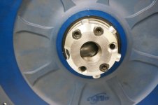
The simplest option with the All Axle motor was to machine an axle insert that has a 17mm dia protrusion out the cable side of the motor, and this would bolt into the fork just like the original wheel:
Rowingbike First Axle.jpg
Rowingbike First Axle installed.jpg

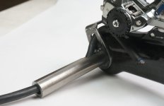
Installed in the carbon fork, the stock torque arm lined up almost perfectly with the holes for the front disk caliper, so with some screws and spacers that cleanly locked the axle against rotation and keep the wheel super secure.
Rowingbike Motor Torque Arm.jpg

It seemed almost too easy. However, installing the motor this way with the cable/torque arm facing the fork meant that the disk brake could no longer be used.

If we try to install the motor with the disk mount inside then the cable comes out the wrong side of the motor and would need some kind of guide to keep it away from the tire before joining up with the top of the fork. I was convinced that regenerative braking would be more than sufficient to replace the lack of a front mechanical brake and was trying to convince the owner of the rowingbike that this would be the case. He was skeptical.
 
Here's what the finished single side fork mount was like.
Rowingbike Motor Front View.jpg


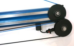
The first pass at the remaining electrical install wasn't too difficult. The back and forth rowing action and pivoting of the handlebars meant normal throttle control during use was out of the question. Luckily though, one of the pulleys in the string/bungee pull mechanisms was around the same diameter as a PAS magnet sensor ring, so I attached a magnet disk to this along with a PAS pickup sensor in order to get automatic PAS assist.

Rowingbike PAS Closeup.jpg
Rowingbike PAS Sensor String Side.jpg


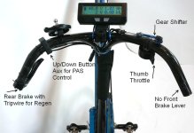
The handlebar controls then had a digi-aux control to the CA3 for adjusting the PAS power level, a thumb throttle both to get rolling from a start and to control the regen intensity, and a tripwire brake sensor on the remaining rear brakes to activate the Regen. It all fit neat enough on the curved carbon fiber bars, with all the controls accesseable without changing hand position while rowing.

Rowingbike Handlebar Controls.jpg


The electrical wires routed easily enough along the brake and shift cables to look decent, with a Phaserunner controller bolted to the under-seat waterbottle mounts.

Rowingbike PAS and First Motor.jpg


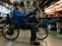
It got finished just in time for rainy season in Vancouver. So most of my test rows I was dressed like this:
Rowingbike Rainy Weather Trip.jpg
 
Great project Justin. What a tease, you got it in testing with a pic in wet weather gear, but leave us hanging about results. I've been wondering about those rowing bikes for years, and now an electric assisted one with the king of ebikes doing the conversion...but no info about results.
 
John in CR said:
Great project Justin. What a tease, you got it in testing with a pic in wet weather gear, but leave us hanging about results.
I've been wondering about those rowing bikes for years, and now an electric assisted one with the king of ebikes doing the conversion...but no info about results.

Oh ha, I wasn't sure if there was actually much of an audience or interest in rowbikes here or was just writing for myself and the customer ;) But actually several people have sent me emails after seeing this with their own rowingbike experiences so I will continue on!

Results You can see the smile on my face in that pictures. That's legit. It took a few trips riding unassisted to get the hang of rowing on the THYS 209 and being comfortable around traffic. The steering is squirrely at first while getting used to the finesse of handlebars that pump back and forth on one axis and steer the other; you absolutely have to clip in the feet and this was my first time ever using SPD's so there was some learning there as well; and shifting gears while rowing on this machine really does not come intuitively, but is essential to get right as you'll just slow down and fall over going uphill if you're in the wrong gear.

I'm used to rowing a sliding seat rowboat where you have these long strokes: crunching up first with arms forward, then extending your legs, pulling your back, and then your arms, then gliding through the water while feathering the oars and getting back for the next power stroke. It's an wonderfully rhythmic motion that I normally do at like 25-28 strokes per minute.

On the rowingbike, the motion is much faster, using the back less and pumping the arms and legs at more like 55-65 strokes per minute. There's also a fairly small band of stroke rate that feels right, and so you really need to be in the right gear for the speed that you're moving. There are many videos from the Derk's rowingbike.com page where you can see the motion.

https://www.youtube.com/watch?v=kmHZGGMfHtg
[youtube]kmHZGGMfHtg[/youtube]

Anyways the machine being in a recumbent position just slices through the air with great efficiency, and it moves at a damn good clip on the flats. Without the motor I was generally passing most of the other cyclists on road on the flats and downhills. But on the uphill sections I had a hard time keeping up.

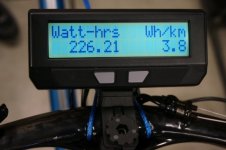
Riding WITH the motor it was super efficient. Normally I ride a cargo ebike, large tires, big upright position with huge saddle bags, cruising ~40kph and I'm about 11-13 Wh/km for my commute. On this electrified rowing machine, I was using typically less than 4 watt-hours / km for the same trip. It just sips energy to sustain the same kind of commuting speeds.
Rowingbike Efficiency.jpg

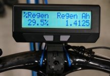
Meanwhile on the downhill sections of the commute I was still regaining a similar number of watt-hours from regen as my regular ebike. But since I was consuming much less for propulsion, the % regen figure was typically much higher, always in the double digits and when I went on a little mountain trip in North Van

Rowingbike Regen.jpg

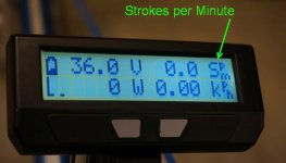
The PAS control mode also worked out just as I'd hoped. Initially I was using the regular CA 3.0 with the "1-wire" sensor type and then any motion forwards or backwards would keep the PAS activated. Then working with Teklektik for the CA3.1 firmware we decided to try making a dedicated rowing bike PAS sensor mode. Instead of counting the number of PAS poles per pedal revolution to show an RPM, it looks at how many times the PAS direction reverses to show the Strokes per Minute.

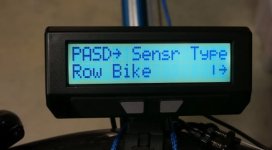
This way it should be possible to add PAS mode to any style rowing bike or other vehicle that has a reciprocating action on the drive chain. It doesn't matter exactly how many magnet pulses there are per stroke, it just looks at each moment the direction of the magnets changes. Anyone with the CA3.1 release firmware can try this out by setting the PAS device to "Row Bike"

Rowingbike CA PAS Setting.jpg

And then, the human power screen will show a display of Strokes per Minute rather than Revolutions per Minute. The #PAS Poles parameter is basically ignored in this context.
Rowingbike SPM Screen.jpg
 
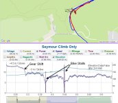
One of the things that was of interest to Derk (the designer and producer of this rowingbike) is how well electric assist could help in reducing the significant swings in velocity between each power stroke and recovery stroke when going up hill. So I decided to hook up an Analogger to the CA3 and record what was going on with the vehicle dynamics on Mt. Seymour. I went up first without assist to establish a benchmark, falling over a couple times as I lost stability at the low speeds. Looped down and then went back up again with 600 watts of PAS power. Here is the trip log of just that section.
http://www.ebikes.ca/tools/trip-analyzer.html?trip=jW6oAw

Here's what you can see zoomed in on that first climb without assist. Initially, the gearing was allowing about 4.5 meters of travel for each rowing stroke, but as my speed slowed down towards 10kph I geared down to 3 meters/stroke. At this point I was hovering around 9 kph when the grade got steeper still, within a few strokes I was at 5kph and then lost balance. That happened at both 0.37 and 0.45 km points

Rowingbike Seymore Climb, No Assist.jpg

I thought it was cool how well you could see the sawtooth pattern in the speed readings from each stroke. This was before we had the CA3.1 firmware with the faster 10Hz logging rate, so the data is logged at just 5 Hz and the actual amplitude of speed fluctuation is surely higher than represented by the peak to peak distance on the graph. On average there's 3 data points capturing the acceleration and then 2 while slowing down. I'm keen to see how this will look with a faster 10Hz log rate.

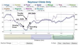
The second time up the hill I was using power assist with PAS set to 600 watts. At around the 1.63 km mark this is no longer sufficient for the grade and I'm clearly slowing down with each stroke, so at that point I hit the throttle to put 800 watts into the motor and start speeding right up again.

Rowingbike Seymore Climb, with Throttle Boots.jpg


Normally I would have set the max PAS assist level to like 1000 watts and then just used just adjusted the PAS level with the aux inputs rather than using the throttle, but for whatever reason I has the max PAS assist power set to 600W when I did this climb and hence the throttle use.

Anyways, you can see that the actual amplitude of the up-down speed oscillations doesn't change much when riding with or without assist in this constant power CA mode. According to this data it's about 0.5 kph in both cases, though in practice this is being averaged and undersampled so the actual speed change must be higher.

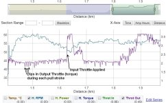
It is also revealing to look at the CA3's throttle output voltage during each stroke too. The CA is trying to maintain constant power while rowing, and the throttle output voltage of the CA is setting the torque on the motor as I'm using a phaserunner motor controller. When I'm on a pull stroke and the bike speeds up, the torque required for a given motor power is less, so there is a dip in the throttle output voltage as the CA's feedback loop responds.

Rowingbike Output Throttle Dips.jpg

If on the other hand instead of using a Phaserunner I was running a conventional ebike motor controller, then as the bike sped up on each stroke, the output throttle voltage from the CA would have to increase in order to maintain constant motor power.

What I really wanted to do was then try setting things up for a similar row up the mountain but with the CA set to a speed control loop instead of a constant power loop. In theory, that should provide extra power to the motor during the recovery stroke and reduced power on each pull stroke so that the total power (human + motor) remains more or less constant at whatever power is required to sustain the speed set point.

Unfortunately it was getting late in the evening and the bike didn't have any lights on it yet, so I rowed home instead.

Then in the days and weeks after that, it rained, and rained, and rained.
...Vancouver
 
I mentioned the rain, and earlier I mentioned this:

justin_le said:
I was convinced that regenerative braking would be more than sufficient to replace the lack of a front mechanical brake and was trying to convince the owner of the rowingbike that this would be the case. He was skeptical.

It turned out that his skepticism was well founded. I did almost all my braking with regen no problem. Until one day in the rainy winter I was rowing to work and a pickup truck pulled out right in front of me. I immediately squeezed the brakes to avoid collision, and with only regen on the front and disk brakes on the rear the back wheel locks and slides out and I'm skidding on my side down the road.

Luckily no impact with a vehicle, but it's clear that having solid mechanical brakes on both the front and rear wheels is critical for safe operating of the rowingbike in an emergency stopping situation like this.

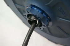
So it was back to the drawing board with the whole motor mount. The problem with using a stock Grin All Axle hub motor on a single side mount is that the cable exits from the opposite side of the disk mount. If we have the disk facing inside the so that the front disk brake can be used, then we have to route the wire back through a hollow axle in the motor to emerge from the disk side.

You can see how we did this for single side installation on the Catrike for Dave in this thread here
https://endless-sphere.com/forums/viewtopic.php?p=1288187#p1288187

The Catrike has a 20mm hollow axle stub that the motor fits over, and so the cable was able to just run right through this hollow axle and emerge on the inside of the frame. With this rowing bike, the hole in the fork is only 8mm, and that's needed for an M8 bolt to hold the axle and wheel in place. I couldn't just feed the cable right through to come out of the left side of the fork, instead needed to find some way of having the cable emerge out the disk side of the motor axle.

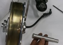
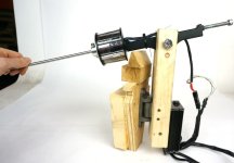
After a very late night with a lathe, milling machine, and welder, I had this here.

Rowingbike Axle Test Fit with Cable.jpg

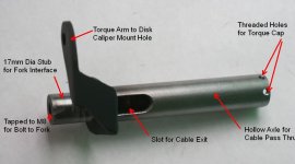
It's a 20mm hollow steel rod with a hole through the middle and a slot allowing the cable to route from the non-disk to the disk side of the motor and then emerge from a slot in the side of the axle. Several pieces of flat steel bar stock are welded to the rod in order to lock this axle against rotation with one of the disk caliper bolts.


Rowingbike Custom Axle Complete.jpg


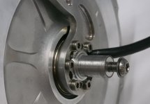
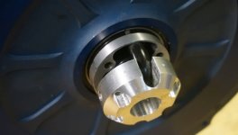
On the other end, there are several tapped radial holes which will hold a metal cap piece that then locks this steel axle to the torque-arm mount of the Grin motor axle. The entire path of motor torque transmission is a bit convoluted but it gets the job done

What's best about this solution is that it requires almost no modifications to the original Grin All Axle motor. The only change from a stock motor was using a round file to make a notch where the cable exits the side of the axle for more clearance, otherwise it would get pinched doing an abrupt 90 degree bend on the exit.


Rowingbike Motor Cable Axle Notch.jpg


This also gave us an excuse to see how well the Grin motor side plates took to blue anodizing in order to match the rest of the bike. With this much work into a custom build might as well go the extra mile :).
 
This is our dry season, perfect weather every day, so I feel for you. Again thx for the detail, I know those posts require lots of time and effort. We may not often reply (nothing useful to add), but there are lots of us who soak up whatever you share.

It will be interesting to see how much difference speed control makes in the speed oscillations.
 
Extraordinary, great to see the detail of the rowbike conversion. Seems like a really good use of ebike technology.

Returning briefly to the "string", I was really surprised to find out that the material is Ultra High Molecular Weight Polyethylene. I was expecting something much more exotic. Of course the polymer is processed in a unique way to yield the remarkably strong, lightweight, flexible fibers. Amazing what material research can achieve.

I rowed in an 8-man shell in college. As pointed out, the rowing action of the bike is quite different than a rowing shell, mainly due to the lack of a seat slide. It is great that the "gearing", of the rowbike can changed, our rowing shell was definitely a one speed. It is a long time ago, but it seems to me that we would start a race with a sprint in the high 40 strokes/minute, then go down to a more comfortable pace for the bulk of a race and then the sprint at the end would be back up to the high 40 strokes/minute. Hmm, electric assist would have been very nice for the rowing shell.
 
richmpdx said:
Returning briefly to the "string", I was really surprised to find out that the material is Ultra High Molecular Weight Polyethylene. I was expecting something much more exotic. Of course the polymer is processed in a unique way to yield the remarkably strong, lightweight, flexible fibers. Amazing what material research can achieve.

Yeah I know, to think it's the same base polymer as all the throwaway plastic bags or soft plastic containers we use every day, and with some magic of chemistry and processing is stronger in tension than a similar cross section of steel.

I rowed in an 8-man shell in college. As pointed out, the rowing action of the bike is quite different than a rowing shell, mainly due to the lack of a seat slide.

In theory at least, it shouldn't matter too much if it is the leg station that is sliding or the seat sliding with the legs fixed. In this case I think one of the other main differences is that the arm and leg motion are intrinsically linked, you can't first pull with the legs only, and then shift thee motion to your arms and back.

I've been pretty intrigued by the rowing rigs that have sliding rigs rather than sliding seats, since it gives exactly the same motion with the arms, legs, and back, but without the large forwards and backwards shift in weight and momentum.
https://www.christinedemerchant.com/rowing-sliding-rigger.html

A reader recently just emailed me this compilation link of rowing bikes which includes a few models that do have a sliding seat though, and I'd love a chance to try one of these to see if it can handle a bit more like a rowboat with the slower paced rowing rhythm.
http://www.geocities.ws/rcgilmore3/land_rowers.htm

It is great that the "gearing", of the rowbike can changed, our rowing shell was definitely a one speed.

That's for sure, though rowing on water you can be pretty sure that the grade is always around 0%. If it deviates much from that you are probably in some trouble :!: :shock:

Hmm, electric assist would have been very nice for the rowing shell.

That will be subject to a separate build thread in the watercraft forum!
BoatDrive.jpg
BoatProps.jpg
 
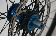
Anyways, carrying on with the rowing bike build. The custom steel axle with the side cable exit just barely fit, the wire bends up 90 degrees and comes up the fork within like 0.5mm from rubbing against the disk bolts. But it did the trick and we've now got the disk rotor and cable on the same fork side and can fit hydraulic disk calipers on the front wheel, no more relying on regen only:

Rowingbike Fork with Motor and Disk2.jpg


For the outside of the motor, I needed to make a cap that bolt bolts radially to the steel axle stop, protects the loop of cable as it wraps around 180 degrees to go back through the core of the axle, and then bolts on axially to the threaded torque arm holes on the Grin Hub.


Rowingbike Axle Cap.jpg


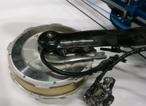
The motor torque couples to this axle cap, then through the radial bolts to the hollow steel axle, which in turn is coupled to against rotation via the metal tab that comes out and lines up with the disk caliper bolts. It's not the prettiest thing but it does the job, and gives us something of a generalized approach to doing single side installations of the Grin Hub that require use of the disk brake.


Rowingbike Axle Cap Mounted.jpg


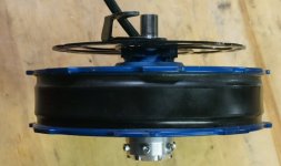
And here's the side view of the final motor assembly. My main regret is that we won't have time to get this piece blue anodized to match the rest of the motor and bike.


Rowingbike Finished Motor.jpg

There's still some tidyup required on the electrical wiring but here is how she looks right now. I've been waiting for some nice weather to do a new set of test rides recording data with the Analogger at the new 10Hz data rate of the CA3.1, and it looks like the weather has delivered.


Rowingbike Complete.jpg
Rowingbike Complete Left Side.jpg

If all goes well I'll be able to do some final ride testing this weekend to validate everything about this install, and then sadly part with the bike. The customer is getting keen to have it in his hands too so my remaining time to play will be short :(
 
Well, the final hurdle in this fairly epic build project was largely finished last weeks, and that is the battery installation. The carbon fiber rowbike frame doesn't have any options for a conventional rear rack where we'd normally put batteries on a build like this. And to make it even more of a challenge, the customer was talking about taking this on trips that are over 350 km on a charge! That might seem crazy, but given that a consumption of 4 Wh/km that I've been typically getting, that would in theory be possible with 1400 watt-hours of battery capacity.

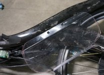
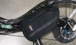
His hope was therefor to fit 16 or 18 LiGo battery modules split in two bags under the seat, with the bags secured by a pair of waterbottle eyelets. In order to give some rigidity to the bags, I made a polycarbonate backing plate matched to the bag profile with a lip on the bottom to secure the batteries.

Rowingbike Polycarb Battery Plate.jpg

It looked OK, but when the bike was upright and hitting bumps the bags would sag quite a bit under the weight of even 4 or 5 LiGos, let alone the 8 or 9 batteries the customer will need in each. And the manufacturer of the rowingbike expressed some concern about whether the bottle eyelets in the thin carbon fiber frame could support this much mass.

Rowingbike Batteries in Bag.jpg

So just last week we revisited the reinforcement so that there was a full width base plate for the LiGos in the bag as well as some bent 3/16" thick aluminum flatbar that went into the waterbottle eyelets and came up to hook on the carbon fiber frame itself. That way they eyelets themselves are serving just to hold the battery bag snug to the frame, and these aluminum hooks will handle most of the downwards load forces to support the weight of the batteries.

Rowingbike Battery Mount Complete.jpg


5 LiGo modules sit snug and upright on the bottom, and it is easy to then stack 3 or 4 more LiGo's on top of these units to really fill out the bag. If the customer goes with 18 LiGos in total, that will result in a 72V 24 amp-hour battery module that should realistically give over 400km of range. You gotta love the efficiency of recumbent bikes in this kind of application!

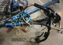
Oh, and one other final detail was the installation of hydaulic brakes. The existing mechanical brake lines on the THYS209 were routed through the carbon fiber handlebar and stem, and also routed through the hollow frame structure as well. Normally I'm all against through frame cable routing since it's a support/maintenance nightmare, but then on the other hand it looks so clean once it's done. Torn between aesthetic and convenience, I let styling win and spent many hours with string and metal hooks and whatnot to pull everything inside the tubing.

Rowingbike Hydraulic Lines.jpg
 
justin_le said:
What I really wanted to do was then try setting things up for a similar row up the mountain but with the CA set to a speed control loop instead of a constant power loop. In theory, that should provide extra power to the motor during the recovery stroke and reduced power on each pull stroke so that the total power (human + motor) remains more or less constant at whatever power is required to sustain the speed set point.

Sooo, with all the batteries properly secured and with the CA3.1 firmware now having the 10Hz data logging rates I finally had a chance to explore this.

What I did last week is take the rowing bike up the same hill used in the Brompton Statorade video, which gives a sense of the elevation and grades, and compared the performance with the CA operating in constant power assist mode and constant speed assist mode. The results are pretty cool.

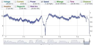
First, the benchmark climb without assist. At the base I could sustain about 10kph but that fell to 6-7kph during the steeper bits of the ascent. The data shows the actual speed fluctuation on each rowing stroke was only ~1.2 kph on average, but it sure felt like more than that. As you decelerate on the recovery stroke it really seems like you need to start pulling immediately or risk slowing down to the point of loosing stability. Around half way up the hill I had to pull over to let a car pass if you're wondering why it goes to zero.

Rowingbike Analysis, No Power.jpg

Then the next bit gets interesting, I set the CA3 to be in a constant speed limit mode of 10kph and repeated the same climb. In order for the CA3 to have a decently responsive speed feedback loop with the Phaserunner I had to increase all the CA's PID gain parameters by about 3 fold from the default values.

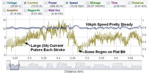
Here, you can see the CA holds the speed fairly steady between 10-11 kph over the entire climb, the amount of oscillation in the speed is reduced to about 0.7-0.8 kph on average (different speed axis autoscaling with preview graph exaggerates this difference), and you see the current fluctuating up and down by about 5 amps (~180 watts) during the climb.

Rowingbike Analysis, 10kph.jpg

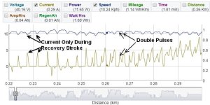
When we zoom in more closely on the data, you can see that the current spike occurs exactly at the dip in the speed. Initially when the hill isn't very steep, there is no power from the motor except during the recovery stroke. So it's like a perfect alternation of human power, motor power, human power, motor power keeping the bike at speed. There is even a bit of regen just before the 0.24km mark when I'm pulling faster than the target.

Rowingbike Analysis, 10kph closeup.jpg


Further along as the grade increases, there is a net current required to keep the rowbike at 10 kph with the ~5A pulses at each stroke super-imposed on that. What I found interesting here is that you can see in in most of the strokes that there is a dip in the speed hump while I'm pulling the rowingbike, and this gets reflected by a double pulse of current. It's as though I'm pulling hard at the start of the rowing stroke, then relax a bit in the middle, and end with a firm tug. I'd love to have a force/torque meter on the system to confirm if this is indeed the case! Or if instead it is caused by the response of the CA3's feedback loop having an initial overshoot.

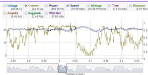
Anyways, the climb at 20kph is similar but with more net motor power. There's an overshoot to ~22 kph when the hill levels out in the middle


Rowingbike Analysis, 20kph.jpg


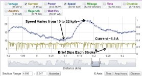
Meanwhile, the climb with constant power rather than constant speed behaves quite differently. Here it is with a 300 watt target.


Rowingbike Analysis, 300 Watts.jpg


The current stays at an average of ~8 amps, with brief downwards spikes at the the high speed point of each stoke. Meanwhile the speed of the rowingbike varies from 10 to 22 kph between the steeper and shallower sections of road. This works fine too, but overall I prefer the climb in constant speed mode, with the motor not only filling in between rowing strokes but also adjusting automatically for the grade hill.

All the data presented in the post is available here:
http://www.ebikes.ca/tools/trip-analyzer.html?trip=J98D1x
 
That is really cool that the logged data shows the CA3 can produce perfect alternation of human and electric motor power to maintain essentially constant speed. I am guessing that you didn't anticipate this particular application when you designed the CA3.

The dip in the current that can be seen in the middle of each stroke is indeed very interesting. As you suggest, it seems likely that during the rowing stroke, the force generated by your push/pull is decreasing somewhat in the middle of the stoke and then increases again at the end. I wonder if this has something to do with the different contributions of arms versus legs over. As a muscle contracts there are changes in joint angle and the moment arm. At different contraction lengths of the muscle there are also different inherent abilities of the muscle to generate force. So contraction of a muscle leads to a position-dependent torque curve. It would be interesting to measure the force exerted by the arms separate from the force produced by legs over a rowing cycle.
 
richmpdx said:
That is really cool that the logged data shows the CA3 can produce perfect alternation of human and electric motor power to maintain essentially constant speed. I am guessing that you didn't anticipate this particular application when you designed the CA3.

For sure that wasn't exactly on the radar at all. But when Derk, the inventer of the THYS system here mentioned that he was hoping for some means that would automatically put out more power on the relaxation stroke to level out the speeds while hill climbing, I had a hunch that this might do the trick automatically. The other option was for the CA3 to have different PAS power levels for forwards and backwards rotation, but I much prefer it happening automatically as a consequence of closed loop speed control.

The dip in the current that can be seen in the middle of each stroke is indeed very interesting. As you suggest, it seems likely that during the rowing stroke, the force generated by your push/pull is decreasing somewhat in the middle of the stoke and then increases again at the end. I wonder if this has something to do with the different contributions of arms versus legs over.

This will be easy for me to confirm by looking at the data when I am rowing hard without any assist vs when I've got the motor power. I'm inclined now to think that this is just an artifact of the CA's control loop and nothing to do with muscle physiology. As in the CA is responding to an initial burst in speed and then scaling back before there is an overshoot and then powering up again, all in the case of one pull stroke on the rowing bike. Weather is a bit crumby now but I'll do a few more logged data trips before I return the rowingbike (now fully electrified) to the customer.

It would be interesting to measure the force exerted by the arms separate from the force produced by legs over a rowing cycle.

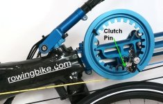
I would love to add strain gauge force sensors on this build too. You could get the combined arm + leg tension from the locking clutch that prevents the string spool from rotating. The shear force on this pin or the mount for the pin has the full cable tension on it.

Rowing Bike Clutch Pin.jpg


Right now with the CA3 in the "Rowbike" PAS sensor mode the torque signal is ignored. But we could in principle have a calibration for Newtons thrust rather than torque, and then the PAS sensor is calibrated not for how many pulses per revolution but in pulses per meter. Then the CA3 would have human energy info from force * distance computations as opposed to torque * rotation.
 
At first I wasn't so sure about this, but man, this turned out to be super interesting. The engineering in that rowing bike is blowing my mind. My attempt to design a rowing bike would have ended up like the drive wheels of a steam engine. This design that even allows for gear ratios is just straight up rocket science to me.

I really loved seeing how you engineered the axle for this build, Justin. And your precision and attention to detail in testing your implementation is amazing. I do software engineering for a living and I'm used to digging down to the nitty-gritty details of data to identify trends, patterns, and behaviors, but I've never translated that into my biking life. I always just went by "seat of the pants" feel to determine if the changes I'd made were going in the right direction. Seeing not only how you logged the ride characteristics, but dug deep to identify specific characteristics was super cool. You're making me want to strap an analogger onto my bike so I can see how my bikes (and myself) are performing.

Thanks so much for sharing this. I'm really enjoying it.
 
Hey Zro-1 and thanks for the feedback and glad to hear that you find something useful or inspiring in all the analysis. I actually seldom use these tools myself so it was fun to actually have occasion to put all the data logging and graphing / visualization stuff to practical use. I think there is something to be gained for people looking to tune the various PID control loops on the CA by studying results this way, especially with the 10Hz logging rate.

Anyways last weekend I finally hooked things up the way that the customer will be running things with a 72V battery pack split between bags on the left and the right, and went riding with a video camera through Stanley Park. I never expected to ride this rowbike offroad but we found ourselves on the trails and bike paths through the forest and the sensation was unbelievable. The strangest juxtaposition of rowing a boat and floating through the woods.
And at 72V the thing flies on the roads. In the tallest gearing I could still have a comfortable rowing rhythm at 45-50 kph and sustain that even on uphill climbs.

We're working on the video edits and I hope to share the result here soon.
 
justin_le said:
Anyways last weekend I finally hooked things up the way that the customer will be running things with a 72V battery pack split between bags on the left and the right, and went riding with a video camera through Stanley Park. I never expected to ride this rowbike offroad but we found ourselves on the trails and bike paths through the forest and the sensation was unbelievable. The strangest juxtaposition of rowing a boat and floating through the woods.
We're working on the video edits and I hope to share the result here soon.

And here she is!

[youtube]DTLFXEdJlj8[/youtube]
 
Crazy bike and integration! In regards to the dip in power on a rowing stroke, that seems pretty typical for rowing. I do the same thing according to rowing machines, as do others at the gym.
 
Back
Top