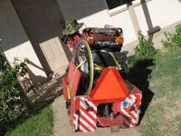
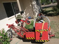
Thanks to Oatnet, I picked up this "little" gem yesterday, out in Sun City (about 14 miles or so away from me, total round trip 27.98 miles).
http://www.ebay.com/itm/Vintage-Used-Crystalyte-Electric-Bicycle-Front-Hub-Motor-Grouping-off-1997-Kona-/121463211940?pt=LH_DefaultDomain_0&hash=item1c47c587a4&nma=true&si=B19o0ufAkFwiMHf78jgnxVnvftg%253D&orig_cvip=true&rt=nc&_trksid=p2047675.l2557
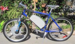
It's a nearly-complete older Crystalyte kit, and was in "untested" condition when I picked it up (meaning, not working). I figured even if each piece needed repair, it'd still be worth having as a backup unit, or parts for other stuff. At the time I didn't really pay any attention to what any models/etc any of it was, just that it pretty much had almost everything necessary to convert a typical bike to e-bike (no ebrake handles, and would need a new throttle). Details about what I found on the kit a little later in the post, with pics here and there to show things better.
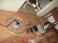
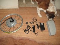
The adventure: Just past midday, after a nearly-uneventful ride (which is more detailed in the CrazyBike2 thread--the ride back was less uneventful), I got there and spoke with Steve, the seller (ebay auction), who was pretty interested in my CrazyBike2, and he sort-of regretted selling the kit after we'd talked a little (though realistically, given his present lack of experience with ebike stuff, he'd be better off buying a new setup than fixing an old one, especially if it needed extensive repairs, whcih at that time was unknown; I didn't even know if *I* could fix it up). I made sure he got the ES forum address off my cargo pods, and he is most likely gonna come poke around.
He advised me that he'd accidentally broken the throttle getting it of the bike he'd gotten the kit from, but that's not a problem as I have a number of throttles, and there's enough of the original left that I could repair it (it's just the twist grip or thumb ring/tab that's missing, and some broken plastics).
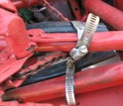
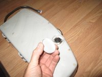
We discussed the battery a little; he said it wouldn't even try to charge, and based on it's weight I figured it would be either NiCd, NiMH, or least likely, SLA. It is in a plastic case made to hose-clamp into a typical frame triangle, and it has a key to turn it on and off, and a charge port with a screw cap over it. The charge port is XLR 3-pin. Depending on how badly it's been used and abused, I said it might be recoverable, but even if it wasn't, I have other batteries I can stick inside that case easily enough.
View attachment 48
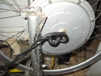
The motor I didn't relaly look at at teh time, other than to note the 26" rim's braking surface has been used a fair bit, and that the thin torque arm has seen better days (it comes close to being able to spin around the axle, but not quite).
View attachment 16
The motor itself looked older, though I didn't (still don't) know very much about all the older Crystalyte brand motors, and so I didn't recognize it for what it is then (despite the label). I didn't even notice it was 48v kit, and assumed it was 36V or less. Not only is a 48V, but it's an X5304.
He watched me ride off and bakc a couple times, we talked some more, and then I headed on home, where the second thing I did was to start taking the battery pack apart.... (the first, of course, was to greet Tiny and Yogi and be slobbered and shed on :lol: ).
So, the battery: It's either NiCd or NiMH; coudln't find any markings on the cells to tell. 40s, so 48V "nominally charged" (1.2v/cell), and 56V "fully charged" (1.4v/cell). The charger, when hooked up and plugged into the wall, simply lights up it's green power light, and flashes the charge light green/red, fairly rapidly. Unfortunately the label on teh charger that probably would've said what that meant is missing.
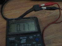
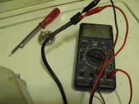
Voltmeter on charge port and output andersons sees essentially nothing: 0.11 to 0.17V, depenidng on how hard I press the meter leads to the contacts (pretty crappy meter leads that have seen much better days).
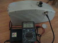
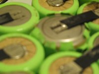
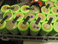
Opened up the case and found the same at the cells themselves. They appear to be something between D size and F size, so I guess if there's an E size, this is probably it. Simple spotwelding, but there's a strip of electrical tape across each row, on both sides of the pack. (nothing in the case could ever short there, so it msut've been for factory safety?).
View attachment 45
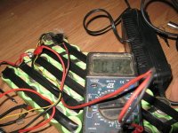
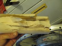
Since the sticky on the tape was almost gone (just gooey) I pulled it all off (nearly fell off). Nothing wrong with the spotwelds I can see, though several cells show signs of swelling, prbalby overheated in teh past. No leaking, though, good sign.
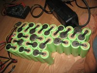
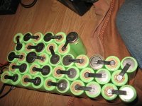
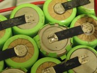
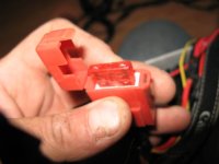
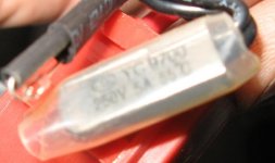
Fuse (40A) checks good as does the thermal cutout switch (55C, 131F), and the diode its probably using as a thermal sensor. Continuity ok everywhere, no shorts.
Next step: force-charge it with the big Sorenson. I set the sorenson to 60V and 1A, and hooked it right across the main pack output tabs. It took a moment for voltage to stop being 0.1V, at 1.0A, but once it did, it climbed rapidly and plateau'd for a minute or two at a little mroe than 12V.
View attachment 39
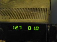
At that point, some cells showed 0V, some a few tenths, and some 1.4V. I let it keep charging like this for several more minutes, until it was around 30V (cuz the controller has a 29V LVC, so the charger ought to be able to try to charge ok above 30V, right?).
Then I disconnected the Sorenson, and hooked p the charger, which now started to charge it normally, at about 2A, in pulses--something in the pack was switching on and off, though, like a relay-- could hear the clicking!
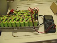
It was not the thermal relay, and I coudlnt' find anything hidden in the pack between cells, etc. So a cell (or several) was actually doing this. Maybe dendrites...3 cells still read 0V even during the charging process.
Next step was to set the Sorenson to 1.4V, 1A, and while the charger was still doing it's thing, I began clipping it across each cell in the string, to see which ones began gobbling current, and which ones kept voltage up, and which shorted it out. Anything that really dropped the voltage down (0.5V or less) and sucked up max current, I turned the current knob up until the cell stopped shorting the voltage out--most fo them that was around 9-10A--then I turned it back down to 1A, and went on to the next cell.
After I did that, all of the cells appeared to be charging at normal voltages again. So it was probably dendrites, and they'll probably come back, but they work for now.
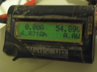
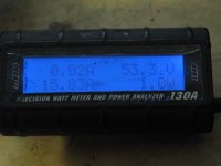
Next up was to just let it charge with it's own charger. But I wanted to know how many Ah it was gonna take, etc., so I cliped the ground wire inside teh pack for the charging port, and put the old well-worn WattsUp from AussieJester in series with that wire (and just clipped it's power wire to the + pack tab). Unfortunately I lost the data while trying to read the thing, cuz the wire tension had "rolled" the Wu over on it's face, and when I rolled it back to check it I pulled the power wire loose, which cleared it's data out.
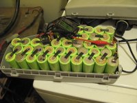
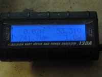
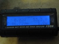
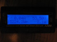
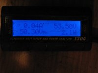
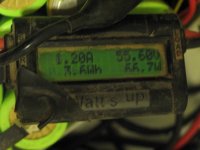
I got pics of the after-that-point charging, it's 2A primary current, then it's pulses of 0A to 1.7A or so,
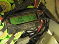
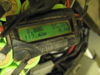
View attachment 24
which it would start once it reached about 120F or so according to a thermometer I stuck between cells
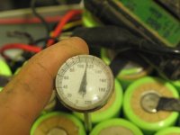
View attachment 21
near the diode (which I'd put down between cells; I don't know where that was orignally; I didn't see it when i opened it up).
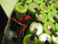
Once it dropped back down to 100-105F or so, it'd restart the 2A charging cycle. I'd guess it was about 3 hours to finish that whole process, including the time before I los the data, so probably it was something around 4-5Ah put into the pack, given the varying currents. At this point I pulled the WU out of the circuit and reconnected the charging ground, then closed up the box. The pack was still pretty warm at this point (uncomfortable to hold for long).
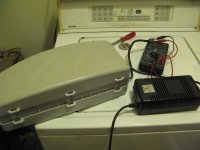
The charger also has a "discharge" button on it, which if you press that for a few seconds, iwhen the unit is in normal charge mode (solid red light, green power light), it changes the power light to green, turns fan on high, and begins a 0.2A discharge of the pack.
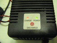
I didn't try doing that for very long, just long enough to see if it would change currents, and it never did--it's probably a fixed resistor being switched in instead of the charging circuit. I dind't explore the guts of the charge rmuch yet, just looked at them:
View attachment 31
View attachment 28
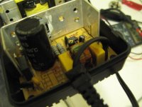
I did reverse the fan in the charger, cuz the AC end of things was hotter than hell, as the fan was set to blow in from the output end of the box, and the tall heatsink there blocks airflow from the rest of the charger. With it set to pull air thru the charger, since it has vents all over it, it works MUCH
better to cool the whole thing evenly.
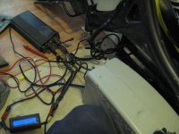
Now I used the partly revived pack to test the rest of the kit: I hooked up the motor, whcih was just sitting in the Coil's fork, to the contorler's halls and phase wires, just plugge d together in order it already had locked together. Hooke dup a different throttle off a different Crystalyte controller (I think one someone donated to me as a fixer-upper; cant' remember who now or what was wrong with it). Also hooked up the PAS; didn't do ebrakes.
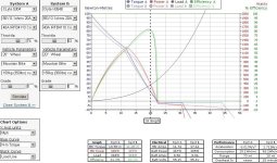
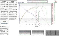
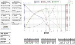
Plugged into battery pack, and twisted throttle: nothing. did some othe robvious things, to no avail. Started measuring voltages at connectors, and verifying connections/mating surfaces, and found that the throttle I'd used (four wire with power meter) wasn't the same wiring as the four-wire with PM that'd come with the kit. Swapped black and white wires on mine to match the original, and VOILA! motor now spun right up, to about 422RPM max. That's about 33 MPH unloaded, with the 26" wheel. If I relaced it into a 20" wheel, it'd only be about 25 MPH unloaded, but should be easier on it at my 20MPH cruising speeds, with a higher current controller (40A instead of 20A), and have better accleration. Of course, since the pack I actualy use has a lot less sag, and is slightly higher voltage, the actual top speed capability would be a little higher, though for my purposes irrelevant as 20MPH is hte max allowed speed anyway.
Teh controller looks like the older Crystalyte stuff that BikeFanatic had sent me (much of which probably isn't around anymore after the fire, since I had a lot of "projects" in boxes in the main room that burned, and I'm sure some of those were there). But this one is a thin one made to clamp around a frame tube, and it's heatsink would then press against teh bike frame and probably be able to use it for additional heatsinking, a little bit.
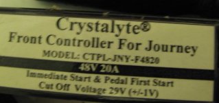
View attachment 6
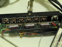
View attachment 4
It's a switchable instant-start or pedal-first controller; switch on teh side of it engages the PAS, and that either disables the throttle or makes it not respond to throttle till the PAS is in use (cranks spinning). I havne't gotten the PAS part working; either something is wrong with the sensor or it's cabling, or the connection between PAS and controller is bad, or I didn't set it up correctly (and/or it's also incompatible with the PAS from the much newer Fusin "1000W" rear geared hub kit I reviewed, which happed to still be on the Diamondback Coil frame I dragged over to the "test area" to put upside down to test the motor in it's fork.)
Label says it's model CPTL-JNY-F4820, and is 29V LVC. While I had it open to verify voltages before I found the throttel wiring reversed, I took pics, fo course. The caps are 100V already; couldnt' see the FETs wihtout opening it up farther than I needed to right hten.
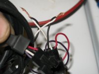
After I found the throttle miswire I put the controller back togehter to test everything. Never did find out why PAS isn't working, so for now the PAS switch is just anothe "off" switch.
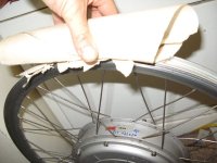
Other than the PAS, it works fine, at least off-ground. I used a once-wet-now-dry-and-stuck-together roll of paper towels I had handy as a "brake" on the rim, to load it down to around 10A, which sliced thru the paper towels pretty quick. :lol: didn't have an ebrake handle handy, but shorting the pins in the brake connector does stop power to the wheel. No regen AFAICT.
I let the pack fully charge up again, then cool overnight, and it dropped down to about 52V. Now it's running a lightbulb discharger test, at about 1A (best I could do with what I had right there, though I have better options in one of the sheds someplace).
View attachment 2
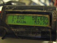
Probably won't have time to Didn't finish before I left for work (and to post this), but it's a start that I can pause, note data down, and finish when I get home. So far it got ~1.6Ah before reaching 32V; was down to 0.7A discharge rate with the pair of 100W incandescent bulbs in parallel.
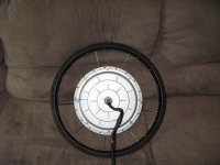
Now, the motor itself. X5304, 26" typical "aero" cheap rim. Some loose spokes, isn't trued up yet. Has 8 cover bolts each side instead of the 9 that seems common on many motors I've opened up so far (including the more recent HSR3548, also by Crystalyte, which has other similarities to this motor).
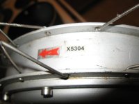
I'd expected rust or something, but this one is clean, *and* it's also painted with anti-rust stuf on the stator and the magnets. Some of the magnets are chipped and paint isn't on those areas; it's possible I did that in opening it, but I didn't find any pieces stuck anywhere so most likely is factory issues (or possibly a prior opening up by someone else).
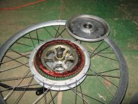
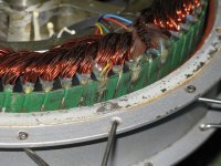
View attachment 14
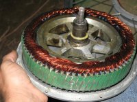
Wires are ok.
View attachment 15
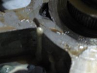
There's an interesting little void in the stator support casting, which isn't likely to give me any issues, but it's something against Crystalyte: between that void and hte ones in the covers of my HSR3548, I wonder how many others out htere have worse ones that cant' even be seen (both of these are quite obvious). And how many of those voids are waiting for the wrong moment to propagate cracks thru the rest of the structure? Most likely very very few people would ever have a problem from them, but it still bothers me.
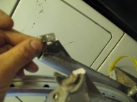
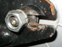
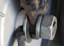
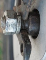
The only "serious" problem with the motor is that the axle is bent on both ends--it looks like maybe a previous owner jumped this thing (a lot?) and eventually bent the axles over time? The really thick part that goes thru the motor, with the really wide shoulders to go against the inside of the dropouts--that appears to be fine. Just the thinner threaded part is definitely bent. No cracks are visible even with a magnifying glass and good light, but it's just as well that I wouldn't be jumping htis thing.
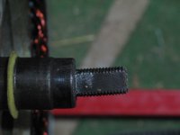
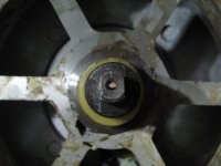
However, whatever I use it on probably would be a heavy hauler, so we'll have to see about ensuring I don't end up with a broken axle and getting stuck somewhere because of it, given the potholes and other street problems I can't always avoid (or even see till too late sometimes--see today's CrazyBike2 post for an example).
It's a front motor, but for me that doesn't mean anything, because I could just as easily do what I did with a 9C front and bolt the threaded part of a regular bike hub to it's right side cover, and turn it into a rear wheel for narrow dropouts.
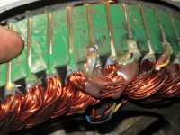
The halls are typical placement and type, though one has it's numbers exposed while the other two are deeper in the glue used to secure them. Wiring all looks good inside and out. It uses anderson pp45s on the phase wires, which I can't tell for sure what gauge wire it is; have to peel back a little insulation at some point to check.
So far, everything either worked or has been fixable or usable as-is. Still to see how it tests on a bike. Gotta put one together with it first. (maybe stick it on the left rear of Delta Tripper, which has the Fusin 1000W on the right rear. Left rear is still narrow dropouts so would probably work there). More later once I have it.
So, again, Thanks! to Oatnet!
http://www.ebay.com/itm/Vintage-Used-Crystalyte-Electric-Bicycle-Front-Hub-Motor-Grouping-off-1997-Kona-/121463211940?pt=LH_DefaultDomain_0&hash=item1c47c587a4&nma=true&si=B19o0ufAkFwiMHf78jgnxVnvftg%253D&orig_cvip=true&rt=nc&_trksid=p2047675.l2557

It's a nearly-complete older Crystalyte kit, and was in "untested" condition when I picked it up (meaning, not working). I figured even if each piece needed repair, it'd still be worth having as a backup unit, or parts for other stuff. At the time I didn't really pay any attention to what any models/etc any of it was, just that it pretty much had almost everything necessary to convert a typical bike to e-bike (no ebrake handles, and would need a new throttle). Details about what I found on the kit a little later in the post, with pics here and there to show things better.


The adventure: Just past midday, after a nearly-uneventful ride (which is more detailed in the CrazyBike2 thread--the ride back was less uneventful), I got there and spoke with Steve, the seller (ebay auction), who was pretty interested in my CrazyBike2, and he sort-of regretted selling the kit after we'd talked a little (though realistically, given his present lack of experience with ebike stuff, he'd be better off buying a new setup than fixing an old one, especially if it needed extensive repairs, whcih at that time was unknown; I didn't even know if *I* could fix it up). I made sure he got the ES forum address off my cargo pods, and he is most likely gonna come poke around.
He advised me that he'd accidentally broken the throttle getting it of the bike he'd gotten the kit from, but that's not a problem as I have a number of throttles, and there's enough of the original left that I could repair it (it's just the twist grip or thumb ring/tab that's missing, and some broken plastics).
We discussed the battery a little; he said it wouldn't even try to charge, and based on it's weight I figured it would be either NiCd, NiMH, or least likely, SLA. It is in a plastic case made to hose-clamp into a typical frame triangle, and it has a key to turn it on and off, and a charge port with a screw cap over it. The charge port is XLR 3-pin. Depending on how badly it's been used and abused, I said it might be recoverable, but even if it wasn't, I have other batteries I can stick inside that case easily enough.

View attachment 48
The motor I didn't relaly look at at teh time, other than to note the 26" rim's braking surface has been used a fair bit, and that the thin torque arm has seen better days (it comes close to being able to spin around the axle, but not quite).
View attachment 16
The motor itself looked older, though I didn't (still don't) know very much about all the older Crystalyte brand motors, and so I didn't recognize it for what it is then (despite the label). I didn't even notice it was 48v kit, and assumed it was 36V or less. Not only is a 48V, but it's an X5304.
He watched me ride off and bakc a couple times, we talked some more, and then I headed on home, where the second thing I did was to start taking the battery pack apart.... (the first, of course, was to greet Tiny and Yogi and be slobbered and shed on :lol: ).


So, the battery: It's either NiCd or NiMH; coudln't find any markings on the cells to tell. 40s, so 48V "nominally charged" (1.2v/cell), and 56V "fully charged" (1.4v/cell). The charger, when hooked up and plugged into the wall, simply lights up it's green power light, and flashes the charge light green/red, fairly rapidly. Unfortunately the label on teh charger that probably would've said what that meant is missing.

Voltmeter on charge port and output andersons sees essentially nothing: 0.11 to 0.17V, depenidng on how hard I press the meter leads to the contacts (pretty crappy meter leads that have seen much better days).

Opened up the case and found the same at the cells themselves. They appear to be something between D size and F size, so I guess if there's an E size, this is probably it. Simple spotwelding, but there's a strip of electrical tape across each row, on both sides of the pack. (nothing in the case could ever short there, so it msut've been for factory safety?).
View attachment 45

Since the sticky on the tape was almost gone (just gooey) I pulled it all off (nearly fell off). Nothing wrong with the spotwelds I can see, though several cells show signs of swelling, prbalby overheated in teh past. No leaking, though, good sign.


Fuse (40A) checks good as does the thermal cutout switch (55C, 131F), and the diode its probably using as a thermal sensor. Continuity ok everywhere, no shorts.


Next step: force-charge it with the big Sorenson.
View attachment 39

At that point, some cells showed 0V, some a few tenths, and some 1.4V. I let it keep charging like this for several more minutes, until it was around 30V (cuz the controller has a 29V LVC, so the charger ought to be able to try to charge ok above 30V, right?).
Then I disconnected the Sorenson, and hooked p the charger, which now started to charge it normally, at about 2A, in pulses--something in the pack was switching on and off, though, like a relay-- could hear the clicking!

It was not the thermal relay, and I coudlnt' find anything hidden in the pack between cells, etc. So a cell (or several) was actually doing this. Maybe dendrites...3 cells still read 0V even during the charging process.
Next step was to set the Sorenson to 1.4V, 1A, and while the charger was still doing it's thing, I began clipping it across each cell in the string, to see which ones began gobbling current, and which ones kept voltage up, and which shorted it out. Anything that really dropped the voltage down (0.5V or less) and sucked up max current, I turned the current knob up until the cell stopped shorting the voltage out--most fo them that was around 9-10A--then I turned it back down to 1A, and went on to the next cell.
After I did that, all of the cells appeared to be charging at normal voltages again. So it was probably dendrites, and they'll probably come back, but they work for now.
Next up was to just let it charge with it's own charger. But I wanted to know how many Ah it was gonna take, etc., so I cliped the ground wire inside teh pack for the charging port, and put the old well-worn WattsUp from AussieJester in series with that wire (and just clipped it's power wire to the + pack tab). Unfortunately I lost the data while trying to read the thing, cuz the wire tension had "rolled" the Wu over on it's face, and when I rolled it back to check it I pulled the power wire loose, which cleared it's data out.

I got pics of the after-that-point charging, it's 2A primary current, then it's pulses of 0A to 1.7A or so,


View attachment 24

which it would start once it reached about 120F or so according to a thermometer I stuck between cells

View attachment 21
near the diode (which I'd put down between cells; I don't know where that was orignally; I didn't see it when i opened it up).


Once it dropped back down to 100-105F or so, it'd restart the 2A charging cycle. I'd guess it was about 3 hours to finish that whole process, including the time before I los the data, so probably it was something around 4-5Ah put into the pack, given the varying currents. At this point I pulled the WU out of the circuit and reconnected the charging ground, then closed up the box. The pack was still pretty warm at this point (uncomfortable to hold for long).


The charger also has a "discharge" button on it, which if you press that for a few seconds, iwhen the unit is in normal charge mode (solid red light, green power light), it changes the power light to green, turns fan on high, and begins a 0.2A discharge of the pack.

I didn't try doing that for very long, just long enough to see if it would change currents, and it never did--it's probably a fixed resistor being switched in instead of the charging circuit. I dind't explore the guts of the charge rmuch yet, just looked at them:
View attachment 31
View attachment 28

I did reverse the fan in the charger, cuz the AC end of things was hotter than hell, as the fan was set to blow in from the output end of the box, and the tall heatsink there blocks airflow from the rest of the charger. With it set to pull air thru the charger, since it has vents all over it, it works MUCH
better to cool the whole thing evenly.
Now I used the partly revived pack to test the rest of the kit: I hooked up the motor, whcih was just sitting in the Coil's fork, to the contorler's halls and phase wires, just plugge d together in order it already had locked together. Hooke dup a different throttle off a different Crystalyte controller (I think one someone donated to me as a fixer-upper; cant' remember who now or what was wrong with it). Also hooked up the PAS; didn't do ebrakes.
Plugged into battery pack, and twisted throttle: nothing. did some othe robvious things, to no avail. Started measuring voltages at connectors, and verifying connections/mating surfaces, and found that the throttle I'd used (four wire with power meter) wasn't the same wiring as the four-wire with PM that'd come with the kit. Swapped black and white wires on mine to match the original, and VOILA! motor now spun right up, to about 422RPM max. That's about 33 MPH unloaded, with the 26" wheel. If I relaced it into a 20" wheel, it'd only be about 25 MPH unloaded, but should be easier on it at my 20MPH cruising speeds, with a higher current controller (40A instead of 20A), and have better accleration. Of course, since the pack I actualy use has a lot less sag, and is slightly higher voltage, the actual top speed capability would be a little higher, though for my purposes irrelevant as 20MPH is hte max allowed speed anyway.
Teh controller looks like the older Crystalyte stuff that BikeFanatic had sent me (much of which probably isn't around anymore after the fire, since I had a lot of "projects" in boxes in the main room that burned, and I'm sure some of those were there). But this one is a thin one made to clamp around a frame tube, and it's heatsink would then press against teh bike frame and probably be able to use it for additional heatsinking, a little bit.

View attachment 6

View attachment 4
It's a switchable instant-start or pedal-first controller; switch on teh side of it engages the PAS, and that either disables the throttle or makes it not respond to throttle till the PAS is in use (cranks spinning). I havne't gotten the PAS part working; either something is wrong with the sensor or it's cabling, or the connection between PAS and controller is bad, or I didn't set it up correctly (and/or it's also incompatible with the PAS from the much newer Fusin "1000W" rear geared hub kit I reviewed, which happed to still be on the Diamondback Coil frame I dragged over to the "test area" to put upside down to test the motor in it's fork.)
Label says it's model CPTL-JNY-F4820, and is 29V LVC. While I had it open to verify voltages before I found the throttel wiring reversed, I took pics, fo course. The caps are 100V already; couldnt' see the FETs wihtout opening it up farther than I needed to right hten.

After I found the throttle miswire I put the controller back togehter to test everything. Never did find out why PAS isn't working, so for now the PAS switch is just anothe "off" switch.
Other than the PAS, it works fine, at least off-ground. I used a once-wet-now-dry-and-stuck-together roll of paper towels I had handy as a "brake" on the rim, to load it down to around 10A, which sliced thru the paper towels pretty quick. :lol: didn't have an ebrake handle handy, but shorting the pins in the brake connector does stop power to the wheel. No regen AFAICT.
I let the pack fully charge up again, then cool overnight, and it dropped down to about 52V. Now it's running a lightbulb discharger test, at about 1A (best I could do with what I had right there, though I have better options in one of the sheds someplace).
View attachment 2

Probably won't have time to Didn't finish before I left for work (and to post this), but it's a start that I can pause, note data down, and finish when I get home. So far it got ~1.6Ah before reaching 32V; was down to 0.7A discharge rate with the pair of 100W incandescent bulbs in parallel.
Now, the motor itself. X5304, 26" typical "aero" cheap rim. Some loose spokes, isn't trued up yet. Has 8 cover bolts each side instead of the 9 that seems common on many motors I've opened up so far (including the more recent HSR3548, also by Crystalyte, which has other similarities to this motor).

I'd expected rust or something, but this one is clean, *and* it's also painted with anti-rust stuf on the stator and the magnets. Some of the magnets are chipped and paint isn't on those areas; it's possible I did that in opening it, but I didn't find any pieces stuck anywhere so most likely is factory issues (or possibly a prior opening up by someone else).


View attachment 14

Wires are ok.
View attachment 15
There's an interesting little void in the stator support casting, which isn't likely to give me any issues, but it's something against Crystalyte: between that void and hte ones in the covers of my HSR3548, I wonder how many others out htere have worse ones that cant' even be seen (both of these are quite obvious). And how many of those voids are waiting for the wrong moment to propagate cracks thru the rest of the structure? Most likely very very few people would ever have a problem from them, but it still bothers me.

The only "serious" problem with the motor is that the axle is bent on both ends--it looks like maybe a previous owner jumped this thing (a lot?) and eventually bent the axles over time? The really thick part that goes thru the motor, with the really wide shoulders to go against the inside of the dropouts--that appears to be fine. Just the thinner threaded part is definitely bent. No cracks are visible even with a magnifying glass and good light, but it's just as well that I wouldn't be jumping htis thing.


However, whatever I use it on probably would be a heavy hauler, so we'll have to see about ensuring I don't end up with a broken axle and getting stuck somewhere because of it, given the potholes and other street problems I can't always avoid (or even see till too late sometimes--see today's CrazyBike2 post for an example).
It's a front motor, but for me that doesn't mean anything, because I could just as easily do what I did with a 9C front and bolt the threaded part of a regular bike hub to it's right side cover, and turn it into a rear wheel for narrow dropouts.
The halls are typical placement and type, though one has it's numbers exposed while the other two are deeper in the glue used to secure them. Wiring all looks good inside and out. It uses anderson pp45s on the phase wires, which I can't tell for sure what gauge wire it is; have to peel back a little insulation at some point to check.


So far, everything either worked or has been fixable or usable as-is. Still to see how it tests on a bike. Gotta put one together with it first. (maybe stick it on the left rear of Delta Tripper, which has the Fusin 1000W on the right rear. Left rear is still narrow dropouts so would probably work there). More later once I have it.
So, again, Thanks! to Oatnet!


