stancecoke said:
First: great work

Nice to hear from you, stancecoke.
Fluctuator said:
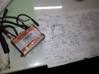
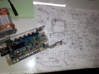
I have few Lishui FOC controllers, that looks like that:
Where are they from? Ebikes? Scooters?
This controllers I found in a box of electronics scrap near trash bin on one of the streets in Berlin about one year ago. There were also some printer parts, broken mobile phones, few lipo-batteries, BMS, etc.
I dont think this FOC controllers from E-Bikes. More chances it is from Scooters. On PA3 port is wire with "TB" mark. I gUess it is maybe light.
Also on PB5 it has digital out with diode, involved in power circuit manage. So I need also to reconfigure it. as well, But cant understand yet how to reconfigure interrupt as well

)) I would like to put it on PB8, because I replaced PAS from PB8 to PB4 (on this controller this pin is not connected anywhere, free)
Fluctuator said:
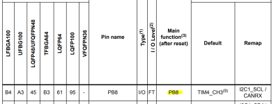
Could you please help to reconfigure PB8 as Voltage Sense (+V) ?
Sorry, but PB8 is no ADC input, you can't read in the voltage with this pin. See the datasheet.
For discussion of the firmware, please join the german forum, in this forum the project has met with little interest so far.
https://www.pedelecforum.de/forum/index.php?threads/open-source-firmware-f%C3%BCr-lishui-controller.61113/
THANKS A LOT! I just saw there voltage divider (Strangely, it makes from 42V -> 4.5V, and how it didn't burn digital input)
I just decided to cut the PCB trace, and now nothing comes to PB8. As I said I want to put there Speed sensor, cause it is easy to access pin on PCB.
On PA7 in this controller comes voltage divider which makes 1.3V from 20V. This 20V coming out of DC-DC step down. It also is feeding MOSFET drivers IR2103. Why does Lishui designer sense DC-DC I have no Idea. I think it will always gonna stay 20V even if battery voltage goes down. I will check later. I can also cut PCB trace and solder a wire from +Vbattery divider to PA7. Its quite easy. But afraid of 4.5V input to ADC. Need to check in datasheet if it is tolerant
stancecoke said:
It has also some kind of CURRENT comparator
That's standard at the Lishui design. Normally it's the fourth channel of the quad op amp (3x phase current, 1x comparator) for Tim1 BKIN on PIN PB12. That's a safety feature for switching off the PWM at overcurrent.
regards
stancecoke
Its big progress for me today! I will go to check your German forum link now. Thank you, again.
Spinning

))))))) :
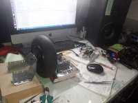
BTW, microcontroller on this Lishui: Stm32f103c8
I would like also to find out what is normal operating temperature of FOC controllers, to make proper size aluminium heat sink. I tried this Lishui today on 42V 0.8A for maybe 10 minutes, temperature of aluminium pad is about 40 celcius. I have few cheap no name BLDC controllers in my diy electric bicycles, and they are not hot after even 1 hour.
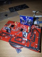
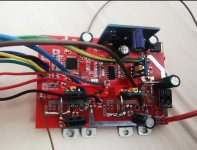 [youtube]https://www.youtube.com/watch?v=62B7nJV4lMw&feature=youtu.be[/youtube]Hello everyone, I saw the firmware Lishui foc by @stancecoke, and decided to make my own board, the board was based only on my knowledge and firmware, as well as on a photo of the operational amplifier. And well, it works. This is the first version of the board, it has brakes, an auto-calibration button, a reverse button, a brake light, a main light, a pas sensor and a throttle stick, eeprom is implemented in the EBICS firmware, and this gives a lot of possibilities, displays can be completed, sensorless calibration (motor inductance and resistance) and many different functions. If you wish, I can publish gerber files, or I can draw the following versions of the board. It should be noted that the board consists of modules (three drivers and dc-dc step-down)