Cycle analyst 2.3 DPS to generic KU controller?

Samd

10 MW
Joined
Jun 28, 2011
Messages
3,750
Location
Ballarat, AU
Hi there,
I was recently gifted a CA 2.3 with the 6 pin connector, including the speedo magnet + wire.
I'm keen to hook it up to a standard KU121 style 12 FET and try it out. I want to use the limiting features with RC lipo and a geared BPM hub.

Looking at the six pin connector on ebikes.ca it is obvious what to do with pin 1 & 2.
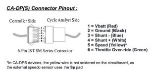
New Picture.jpg

I'm not sure what to do with pins 3,4 and 6.
For pins 3&4 I'm assuming I need to solder these to the ends of the shunt on the KU's PCB. Not sure if I need to cut the shunt though or leave it intact.

And for pin 6 I'm not sure if this is to join the signal of my hall throttle to the CA, or to join the CA to the throttle signal input on the controller? In both of those scenarios, in my mind I have three things to join, not two, so one is left unused.

If anyone could enlighten me I'd be most appreciative. Or perhaps it's not doable. I'm sure someone has attempted it before....
 
Samd said:
For pins 3&4 I'm assuming I need to solder these to the ends of the shunt on the KU's PCB. Not sure if I need to cut the shunt though or leave it intact.
Solder to the end of the shunt. Don't remove it!
Shunt -ve (blue) goes to the same side of the shunt as GND.

Throttle override is a different story, a diode is required.
 
Samd said:
Hi there,
I was recently gifted a CA 2.3 with the 6 pin connector, including the speedo magnet + wire.
I'm keen to hook it up to a standard KU121 style 12 FET and try it out. I want to use the limiting features with RC lipo and a geared BPM hub.

Looking at the six pin connector on ebikes.ca it is obvious what to do with pin 1 & 2.
I'm not sure what to do with pins 3,4 and 6.
For pins 3&4 I'm assuming I need to solder these to the ends of the shunt on the KU's PCB. Not sure if I need to cut the shunt though or leave it intact.

And for pin 6 I'm not sure if this is to join the signal of my hall throttle to the CA, or to join the CA to the throttle signal input on the controller? In both of those scenarios, in my mind I have three things to join, not two, so one is left unused.

If anyone could enlighten me I'd be most appreciative. Or perhaps it's not doable. I'm sure someone has attempted it before....
This is covered in the CA V2.3 manual downloadable here.

Pins 3 and 4
The wiring is as shown in section 2. It's best to attach pins 3&4 to pads/traces adjacent to the shunt. If you solder directly to the shunt you will no doubt alter the value slightly. On the other hand, since you actually don't know the shunt calibration, you will need to guesstimate it anyway so solder where convenient. Attach the blue Shunt(-) wire to the same side of the shunt as controller Gnd.

A better choice is to use an external CA shunt which solves the connection and calibration issues in one shot. It just plugs into your CA-DP cable. You can use either the V2 style (SHUNT-SA) or the newer V3 style (SHUNT-CA3) which is the same except it has a handy little breakout cable that brings out the green throttle wire.

Pin 5
Not used with CA-DPS configuration.

Pin 6
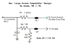
  • If you want to run the V2 in normal limiting mode, see section 7.1 of the manual. You will need to eyeball the PCB. Typically you will need to add the diode and may need to add a resistor and/or short an existing resistor. However, that manual is a little dated. A more recent setup is shown here (this is actually for an Infineon controller, but the principle is the same. Your KU controller may not have R9 or the value for R8 may be slightly different. In any case, attach a new resistor R1 that is about 1/10 the value of R8 and use it for the pin 6 throttle override signal. You attach your throttle to the normal controller throttle connection.

    CA-LargeScreenCompatibleThrottleOride.png
  • On the other hand - a better solution may be to run your V2 with 'Current Throttle' to make the response more linear and eliminate twitchyness. This is covered in section 9.3 of the manual. Here you:
    • remove your throttle from the controller and run it into the CA POT input
    • move the CA-DP cable green wire on the CA PCB from the ThD to the ThO pad, and
    • connect the other end of the green CA-DP wire directly to the controller throttle input (no resistors or diodes required).
    • set the CA AuxVoltageFunction Setup parameter (section 8.17) to 'Current'
    • set the CA MaxAmps Setup parameter (sectiion 6.5) to the current rating (or lower) of your controller
    • optionally, the CA AuxThreshold setup parameter (section 8.18) can be adjusted to eliminate any initial throttle dead zone
    • optionally, the CA IntAGain setup parameter (section 8.9) can be adjusted to eliminate any throttle 'hunting' or oscillation
    This will give you a 'Current Throttle' feature similar to that found in the V3. With Current Throttle, the throttle input voltage scales the controller current linearly 0-100%. So, if you have a reasonably linear throttle, a 25A controller, and twist the throttle 20%, you get exactly 5A of current.

    I am a tremendous fan of Current Throttle and highly recommend you give this a go - particularly if you are overvolting/overamping your gear motor which tends to make a big power step in the midrange - this setup will make the throttle control smooth and easy.
So - in the end, the KU (or any controller) can drive the V2.3 without modification by using a CA (V3) external shunt and Current Throttle. :D
 
Thanks guys,
that makes good sense. I think I had been reading the wrong version of the manual. Thanks so much.

My main use was to adjust the current shunt in steps as I have been conducting a bit of a binary search when it comes to how much a Code10 can handle at 15s. Only lost one so far :p

Thanks again.
 
Samd said:
My main use was to adjust the current shunt in steps as I have been conducting a bit of a binary search when it comes to how much a Code10 can handle at 15s.
In this case your modified controller shunt would need to be recalibrated to allow use of the CA for current monitoring - see Appendix A of the V3 Unofficial Guide.

I think using the CA V3 external shunt may be the best answer for you. Just hook up the shunt with the same style connectors you use to power your controller and plug it in-line - either temporarily or permanently. This will get you monitor-only mode for voltage, current, and all the logging while you tinker the controller shunt. You could also either fabricate and calibrate your own external shunt or use a similar ammeter shunt from eBay - it needs a resistance in the neighborhood of 1mOhm.

To get Current Throttle going as well, attach the single green wire from the breakout cable of the shunt to a connector that mates to your controller throttle (don't connect the +5 or Gnd pins) and plug the new connector into your controller throttle connector. You will need a connector on the CA PCB for POT,+5,Gnd to receive your throttle connector. Make the minor PCB connection mod (above). Done.

With everything external and no controller mod, you could use the same rig to fiddle shunts on different controllers fairly easily.
 
tek,

How critical is the R1 being 1/10 of R8 and what is the reason for this?

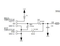
I need to connected up the latest model 2.3 CA to a EB206. I was just going to short out R36 and connected the CA throttle out to SLA. The latest CA 2.3 has a diode already installed in the throttle out circuit.

In this case, the resistor marked R36 is the same R1 in your diagram. So should I install a 220 ohm or seeing the resistance valve is so low, does it really matter?
 

Attachments

  • Capture5.JPG
    Capture5.JPG
    14.4 KB · Views: 2,265
If you want to solder your present shunt in steps, don't use that CA to measure the current unless you use an external shunt, because each time you solder the shunt, the current will actually go up, but the CA will show it goes down. You need to calibrate the CA anyway, and again each time you solser the shunt, so you must buy either an external shunt (any one will do that can handle the current) or use a cheap wattmeter to do your tests, and then use it to calibrate the CA when you're happy.
http://www.ebay.co.uk/itm/Digital-60V-100A-Battery-Balance-LCD-Voltage-Power-Analyzer-Watt-Meter-New-/131023075309?pt=UK_BOI_Electrical_Test_Measurement_Equipment_ET&hash=item1e819577ed

or you can use use a loop of wire as a shunt. See this Excel spreadsheet:
 

Attachments

  • Current Measurement.xls
    95.5 KB · Views: 72
Kepler said:
How critical is the R1 being 1/10 of R8 and what is the reason for this?

I need to connected up the latest model 2.3 CA to a EB206. I was just going to short out R36 and connected the CA throttle out to SLA. The latest CA 2.3 has a diode already installed in the throttle out circuit.

In this case, the resistor marked R36 is the same R1 in your diagram. So should I install a 220 ohm or seeing the resistance valve is so low, does it really matter?
Shorting R36 and connecting SLA directly to the V2.3 will work perfectly. Use the 220ohm resistor if you want to run a V3.

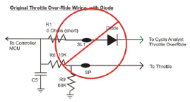
Here is an illustration of the older standard 'V2 compatible' CA-DP interface - it is exactly as you describe although it includes a diode to accommodate earlier model V2s that did not themselves possess an internal diode (the CA works fine with 2 diodes as would occur using a later model V2 with this interface).

V2CompatibleInfineonMod.png
The low value resistor is a compromise that allows the controller to be used with either a V3 or a later model V2. It provides a small bit of protection to the uproc in the V3 case and the 10:1 resistor ratio is large enough that the CA signal can still overwhelm the operator throttle in the V2 'limiting' case (not quite as effective as a short - but close enough).
 
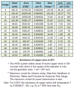
If you want to fabricate your own external shunt, you may find this table useful. For example, about a foot of #10 wire will get you pretty close to the 1mOhm the CA likes to see. You will need to calibrate this by adjusting the CA RShunt value (see link to V3 Guide above), but this should get you in the ballpark.

WireResistanceTable.png
As you can from the note on the table, the resistivity of copper varies quite a bit in the normal seasonal temperature range for ebikes. This makes it a poor choice for shunts unless you live in a part of the world with fairly consistent year round temperatures. Commercial shunts use temperature-compensated alloys to eliminate this undesirable effect. Still - good enough for bench tests in the shop...
 
Thanks for that tek.

So based on the diode direction of flow, the CA pulls the voltage down. Is that correct? My limited electronics experience is showing through here but I previously thought the CA pushed a voltage to the controller.

In regards to the shunt setup, I always calibrate this with an inline amp meter so no problems there.
 
Kepler said:
In regards to the shunt setup, I always calibrate this with an inline amp meter so no problems there.

Same plan here. Turnigy wattmeter inline.
 
Kepler said:
So based on the diode direction of flow, the CA pulls the voltage down. Is that correct? My limited electronics experience is showing through here but I previously thought the CA pushed a voltage to the controller.
Your analysis is spot on - the CA limits the operator throttle voltage by sinking current - for the V2 legacy 'limiting' case. For the case of V2 'Current Throttle' or V3 'normal' mode, the current flow is reversed and the CA sources current to apply the controller input voltage.

Take a look at the illustrations in the short 'Errata' document here - sections 2.1 and 2.2. These show configurations and current flow for four possible controller and CA modes when connected to a V3 - but the idea is the same for the V2. It appears the V2.3 PCB is really a V3 PCB with PAS, TRQ, and Temp sections removed so the 'Errata' illustrations apply directly.
 
Now I am clear. Thanks for explaining the difference. I should have picked that up from your excellent documentation :oops: but I finally got there.

Most of my experience with CA direct connection with a controller has been using a CA3 which is why a presumed the current direction was from the CA to the controller regardless of CA model. :)
 
Back
Top