DIY 10S4P ebike battery BMS not charging

trackebike

10 mW
Joined
Sep 6, 2020
Messages
24
I'm having trouble with an ebike pack that I have built. Cells are Samsung 3500ma. The problem is that the charger light shows green but the individual cell groupings all measure 3.64-3.65V. The pack is balanced but I would have expected a higher voltage for a fully charged pack.

The charger is an inexpensive 2A unit I purchase off of ebay, it was advertised as an ebike 36 volt charger. It's open circuit voltage is ~42 volts. If I bypass the BMS the charger light goes red indicating it is charging.

I believe the problem is my BMS who's label is indicated below. I think this BMS is intended for a LIPO battery and not for LION. I can't read the Chinese, but I see the 3.7 volt check mark. Is my hunch correct? a LIPO BMS?
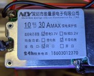
mybms.jpg
 
LiPo and what people call LI-ion are both nominal 3.6-3.7V similar stop-charge voltages, supposedly 4.2V but better for longevity to stop at between 4.05 and 4.15 depending on C-rate.

It is LFP that is lower nominal 3.2V-3.3V, spec'd to stop-charge around 3.6V but again much better off stopping sooner.

LTO is the other LI chemistry that is lower, but as in much.

The charger may just be faulty if not mislabeled.

First discharge, below 3.2 or so then charge manually, watching, bypassing the BMS to eliminate that.

I assume your DMM is confirmed accurate?
 
My DMM is accurate.

Are you stating that the charger won't charge unless the cells drop to a lower voltage first?

I already confirmed that the batteries charge if I bypass the BMS (light on charger goes red I can see the voltages increase on the cells over time), but the charger does get a little warm while doing this.


I bought the BMS on ebay
The only unusual thing I noticed was the ebay ad indicated the following connections which I believed to be incorrect.
The diagram shows that P- is unused. I connected P- to the negative load like every other BMS. Although point is mute, since I am charging without load connected.

mybmshookup.jpg

..and here is what the ad stated:

Features:
The protection board is for 10 series cell Li-ion batteries, it can be used for 3.7V ternary batteries, manganese acid batteries and cobalt acid batteries.

Support overcharge protection, over-discharge protection and short circuit protection.
It is suitable for electric car, electric power assistant car, skateboard car, inverter, etc.
With temperature control protection function, safe and reliable.

Specifications:
Applicable voltage: 36V
Applicable power: <1000w
Max. working current: 30A
Continuous maximum current: 20A
Overdischarge protection voltage: 2.6v
Overcharge protection voltage: 4.25v
Charging current: max. 20A
High temperature discharge: 75 ℃
Low temperature charge: - 7 ℃
Weight: about 60g
Size: 64mm*35mm*9mm
 
trackebike said:
My DMM is accurate.

Are you stating that the charger won't charge unless the cells drop to a lower voltage first?
Yes of course once a pack is full you are only harming it trying to keep pumping current in.

The canonical definition of "to the max 100%" Full

which is harmful to longevity

especially letting the pack just sit at that level

is, CC stage, get to max rated voltage, then hold Absorb / CV stage as current falls, until amps trail down to is 0.02C

Getting the pack down to 50-70% SoC allows you to datalog V&A, watch the curve, confirm things are normal.

From 95% and up only, does not give much data.

If the pack is LFP you will harm it trying to push over 3.6V, could even risk thermal runaway.

I would use a slow rate, well under 0.5C, and set CV to 3.55V and see what it does.

Then 3.7V, if LFP each increase of 0.1V should only maintain a decent current rate for a minute or so, then amps dropping very fast.

If a 3.6-3.7V "LI" chemistry like NMC or LMO, the cells should remain fully "thirsty" right up past 4.0V

 
The cells are Samsung INR18650-35E. High drain lithium ion. These are brand new cells from bulkbattery.com

Right now I have the pack charging and I am bypassing the BMS. The BMS is hooked up but I have the charger clip leaded to the positive and negative of the pack. I started at an overall voltage of 36V. Right now I am at 39.5V.

The charger is functional. The charging light is RED and I confirmed with an inductive amp meter that the charge current is 2 amps as expected.

I have been periodically measuring the individual cell groups and they are maintaining balance as they are charging.

I have re-verified my balance wire connections and they are correct.

The problem is I can't charge through the "C-" connection of the BMS with the charger. When I attempt that - I get a green light on the charger and measuring the cells show no charging progress. As far as I can tell, there must be something wrong with the BMS. My expectation is that if I start at 36V and I connect the charger to the BMS as intended through "C-" then after a couple hours it would charge up to around 42v and then the charger light would turn green.
 
Something is wrong with the "C-" connection on the BMS. If I try to measure with the DMM between "C-" and V+ of the battery the DMM shows no voltage. It is like it is open.

Do they typically have an on board fuse for the "C-" connection? OR is the BMS purposely preventing charge because it believes it has detected an error condition?

The battery is fully charged now (42V) and I have re-assembled the pack. I'll ride the ebike over the next few days and deplete and try the charger again. I have ordered an alternate BMS and will probably install it the next time I crack open the pack.
 
Yes, being able to easily bypass / remove / replace the BMS is good design.

That is often the weakest link, such a huge variety of dirt-cheap crap quality units people don't realize good quality costs more than they want to spend on the pack as a whole.

But really "a BMS" is just a collection of functionalities, no reason to try to get them all from a single device.

With charging, the charger can have all the intelligence, even handle the balancing.

Or a dedicated balancer if you want to maximize longevity, just do it occasionally at the SoC level / voltage you choose.

The BMS then is just a failsafe backup at the cell/group-level. You do not need to charge **through** the BMS, just monitor voltages and wire a relay to cut off the charger in case its regulation circuitry fails.
 
FWIW, this is my first ebike build. I'm no stranger to playing around with high drain lion cells. but this is the first time I've played around with a large number of them.

The ebike I built up using a Ebikeling 500 watt rear hub kit. I used 2"x3" PVC downspout to make the battery case. Top and bottom caps were 3d printed, as was the mount to the frame. It's a 10S4P configuration. 14 amp hour. Probably too much battery. i'm thinking for my use 10S3P would have been fine.

The goal was to have an ebike that I could ride home even if the electric drive failed. I'm not looking for a moped, I want to ride the bike further, like 65 miles and to use the power only when I'm heading home and have some big hills to climb.

Frame is an aluminum track frame from bikeisland.com. front wheel was left over from my road bike after I updated it to carbon rims. Other parts like brakes and crankset were purchased off of ebay.

Total bike weight is around 37 pounds.

I have no front derailleur, so I installed a wide range rear cassette/freewheel (11-34T). Chainring is 46T, No problem climbing hills without electric assist. Planning on a 26 mile shakedown ride tomorrow.

myebike1.jpg


ebikedrive.jpg
 
Is the reverse seatpost a compensation for track bike geometry?
 
The seat post is a nitto 66. I find that it works well with the pursuit handlebars. Its more about personal preference than the frame geometry.
 
Back
Top