
Soooo guys I'm trying to make a compact soft-latch power button(single momentary push button type).
Required features are :
- Circuit should always start in OFF position (auto-reset or power on reset) ;
- Should work as quick press to power ON, hold 2 seconds to shut down ;
- Must be compatible up to 60V ;
- Must be able carry the battery's nominal voltage to the load it switches ON and OFF ;
- Must be as compact and affordable as possible without compromising reliability.
To be precise about the high voltage switch side, I'm going to use it to switch a Ben Vedder's / Fetcher anti-spark ON and OFF, it comes with a 12v zener diode on the excitation pins and needs at least 20V to go HIGH (else it stays LOW).
I posted on stackexchange about it ; the site is a bit unforgiving when you lack accuracy in description -which might be my case : https://electronics.stackexchange.com/questions/360896/soft-latch-auto-reset-off-hold-on-press-button-is-the-schematic-correct
Here is the original topic (started in november) :
https://www.electric-skateboard.builders/t/soft-latch-switch-single-button-on-off-reset-for-vedder-anti-spark-bom/37746
Here is the current schematic :
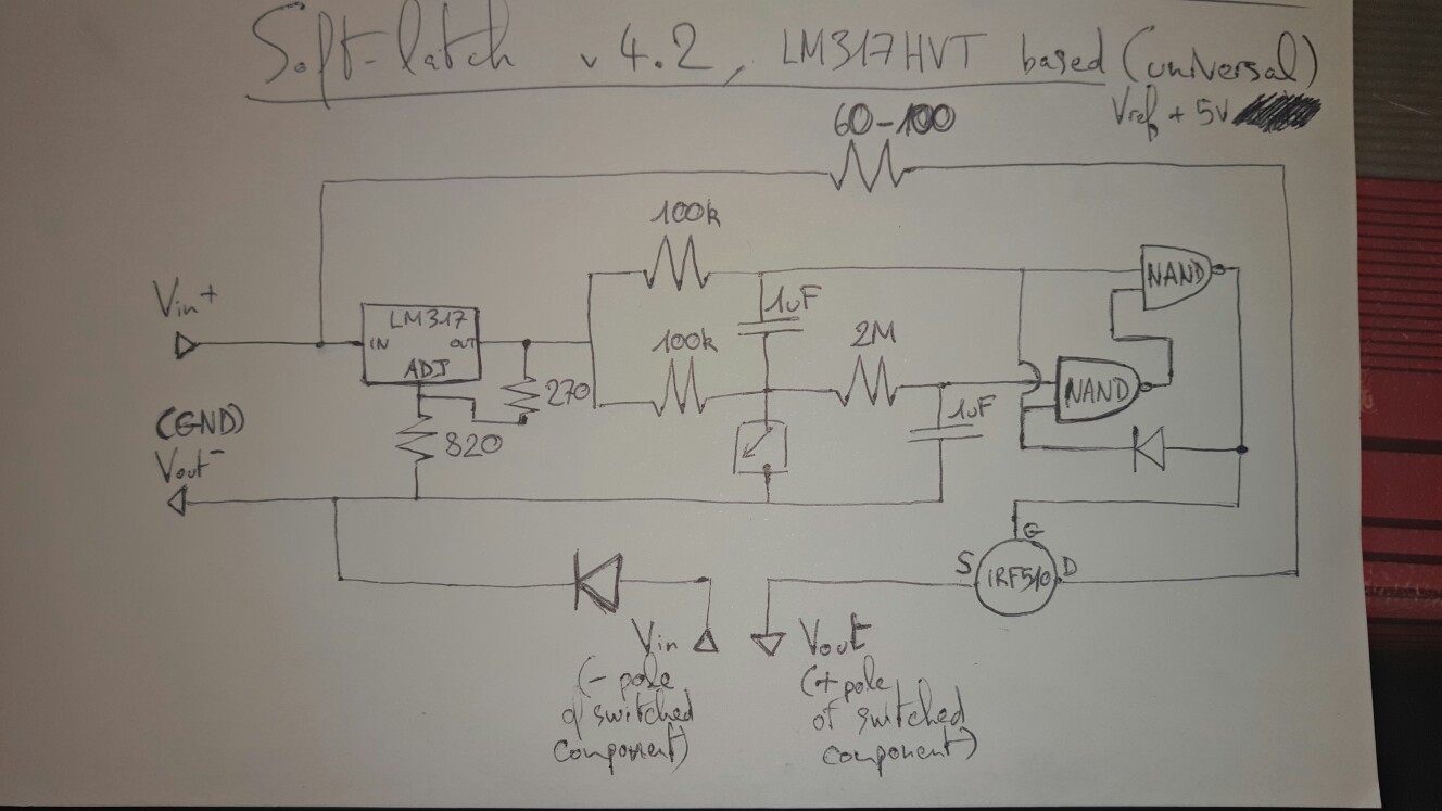
I circled the BOM as follow (for up to 60V ability) :
I've gone back and forth on this already, learnt lot of things but my knowledge is still basic and limits my insight.
So far, I got all the components rounded up imho. Now about the circuit itself, eh I hope you might help me check schematics for good to get this thing working !
Do you see anything wrong ? How would you improve it ? Also, do I need to put the caps specifically in one direction ? I tried various layouts on the breadboard, probed different reactions on the circuit but no successful result yet.
Required features are :
- Circuit should always start in OFF position (auto-reset or power on reset) ;
- Should work as quick press to power ON, hold 2 seconds to shut down ;
- Must be compatible up to 60V ;
- Must be able carry the battery's nominal voltage to the load it switches ON and OFF ;
- Must be as compact and affordable as possible without compromising reliability.
To be precise about the high voltage switch side, I'm going to use it to switch a Ben Vedder's / Fetcher anti-spark ON and OFF, it comes with a 12v zener diode on the excitation pins and needs at least 20V to go HIGH (else it stays LOW).
I posted on stackexchange about it ; the site is a bit unforgiving when you lack accuracy in description -which might be my case : https://electronics.stackexchange.com/questions/360896/soft-latch-auto-reset-off-hold-on-press-button-is-the-schematic-correct
Here is the original topic (started in november) :
https://www.electric-skateboard.builders/t/soft-latch-switch-single-button-on-off-reset-for-vedder-anti-spark-bom/37746
Here is the current schematic :
I circled the BOM as follow (for up to 60V ability) :
- 1x LM317HVT linear voltage regulator + 1x 270ohm & 1x 820ohm resistors (fixed 5V output)
- 1x resistor between 60 & 100 ohm
- 2x 100kOhm resistors
- 1x 2M resistor
- 2x 1uF capacitors
- 1x CD4011 NAND chip (contains up to 4x NAND gates)
- 1x IRF510 mosfet to switch the load in HIGH / LOW
- 2x diodes for polarity protection
- 1 momentary push button (I got the flatest and smallest one available to me, others might prefer a bigger one)
I've gone back and forth on this already, learnt lot of things but my knowledge is still basic and limits my insight.
So far, I got all the components rounded up imho. Now about the circuit itself, eh I hope you might help me check schematics for good to get this thing working !
Do you see anything wrong ? How would you improve it ? Also, do I need to put the caps specifically in one direction ? I tried various layouts on the breadboard, probed different reactions on the circuit but no successful result yet.
