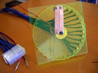
What is important with these power supply as charger is that you NEED to know the equivalent load that represent one cell when it is fully discharged at let say 2.5V / 3.6.
I am finishing my large 12s multi DC-DC charger and i needed to calculate that to avoid the dc-dc to overload.
Also you need to know what is the voltage of a cell when charging at different current. (if you discharged a cell down to 2.5V, after that if you apply let say...10A on it.. it should rise around 3.0V (AT THE CELL TAB)
so if your charger apply 3.6V and apply 10A and your cell is 3.0V, the 0.6V will be somewhere for sure!...in the wires, resistors or voltage connections loss...
OR you can also limit the current of the power supply and then tranbsform it in a CC-CV. Some power supply that are rated 20A like the one showed above and that i've been talking about in "the single cell charging post" can deliver more and their current limit will only limit the INPUT CURRENT! so that mean if they are rated 20A at 5V(that you re-adjust to 3.6) that's 100W.. so if your voltage is readjusted to 3.6V, that current limit become 100/3.6 =28A... and the output component will not hold that for long!..
what you need if you want to keep the cc-cv feature and not use resistor to dissipate the vooltage and only have a CV charger... is to control the current limit!
That'S what i've been working on for few weeks. Right now, i'm mooding the current control resisitor of the PWM IC on the DC_DC board

I am limiting it to 15A instead of 30A.. for two reasons: the first is that i dont want to have 24 conductors of 10AWG between the charger and the cells! 30A is too big current than i need from now and the cells will not like that for their cycles lifes!
Second, the main power supply that give the 48 or 72V on each of their input would not be able to suply all 12 dc-dc at the same time if they give 30A at 3.6V or 4.2V !
I will also use the voltage sensing option they have.. that option ensure that the charger will not be affected by the voltage loos in the long wires between the cell and the charger. so each of the dc-dc will have 4 wires at their output. 2 for the high current main output and two for the voltage sensing that will be connected directly to the battery tab to ensure that i have 3.600 or 4.200V on the cell.
As you know, it take me long time to finish this charger that i've been talking from many months but i will finish it in the next 2 weeks... that will be a universal li-ion battery charger!
Doc


