kenkad
100 W
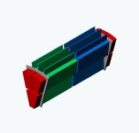
I did not want to hijack Miles thread any further, so I have posted the following coil concept I plan to use in my dual rotor axial flux motor design. I redid my original coil end flux directors so that they are easier to manufacture. I plan to use a Somoloy powdered disk as the starting point for the coil end flux directors. One of the JPGs shows how a Somoloy disk is machined into segments with slots for the lam core. The Somoloy material is not cheap so I had to define a way to get segments that were different size for my coil assembly. The segmentation concept allows me to make enough coil end flux directors for two coil assemblies from one Somoloy disk. The motor has a total of 12 coil assemblies. Each coil assembly has three individual split flat copper wrap sub coils. The coil assembly is shown in one of the attached JPGs. In each coil assembly, an Aluminum wedge on either end is used to fix the position of the flux directors and the sub coils. The plan is to assemble each coil assembly in a fixture so the spacing is correct and then the flux directors are epoxied to the Aluminum wedge and the core lam. Then each assembly is placed into the stator core and the plan was to grind the faces of the Somoloy flux directors so that a very precise flux gap could be created between the coils and the rotors.
Some other notes. I am interested in a motor that has six 3-phase groups. This means six FET driver PCBs with a microcontroller (slaves). A seventh microcontroller decides the sequencing of the six slaves and also determines which of the six 3-phase groups are used depending on the torque requirements. This approach reduces the Amps through each 3-phase group and allows each slave to have identical software, just time shifted. I do not plan to use Hall sensors. I will be using a magnetic rotation sensor for rotor/stator positioning. There are a number of other design issues I want to be able to analyze that I do not plan to discuss at this time.
As I have stated before in one of Miles posts, I am not a motor designer. My interest is in trying motor concepts that others (as far as I can determine) have not tried before. I certainly appreciate suggetions that I may not have thought through. This project is already two years old and I still have not cut any metal. It will be most likely another year before I have the time to pursue this. I wanted others, who (like Miles/Lebowski, etal) are considering axial flux motor design, to review and comment so that we can make some cooperative progress. Thank you for looking.
kenkad