enrengineering
100 mW
- Joined
- Apr 2, 2020
- Messages
- 41
Hello ES members,
I've been into electric vehicles for a while, and after reading APL's and HalbachHero's threads I got some inspiration and decided to start tinkering about building an axial flux motor (and found out that i'm not the only one that likes this stuff ).
).
I'm currently studying mechanical engineering and I have a lot of interest on electric vehicles, I've built two electric go karts so far and going strong, also, I spend all my summers working on a electric motor maintenance and repair shop and I learned a lot working there.
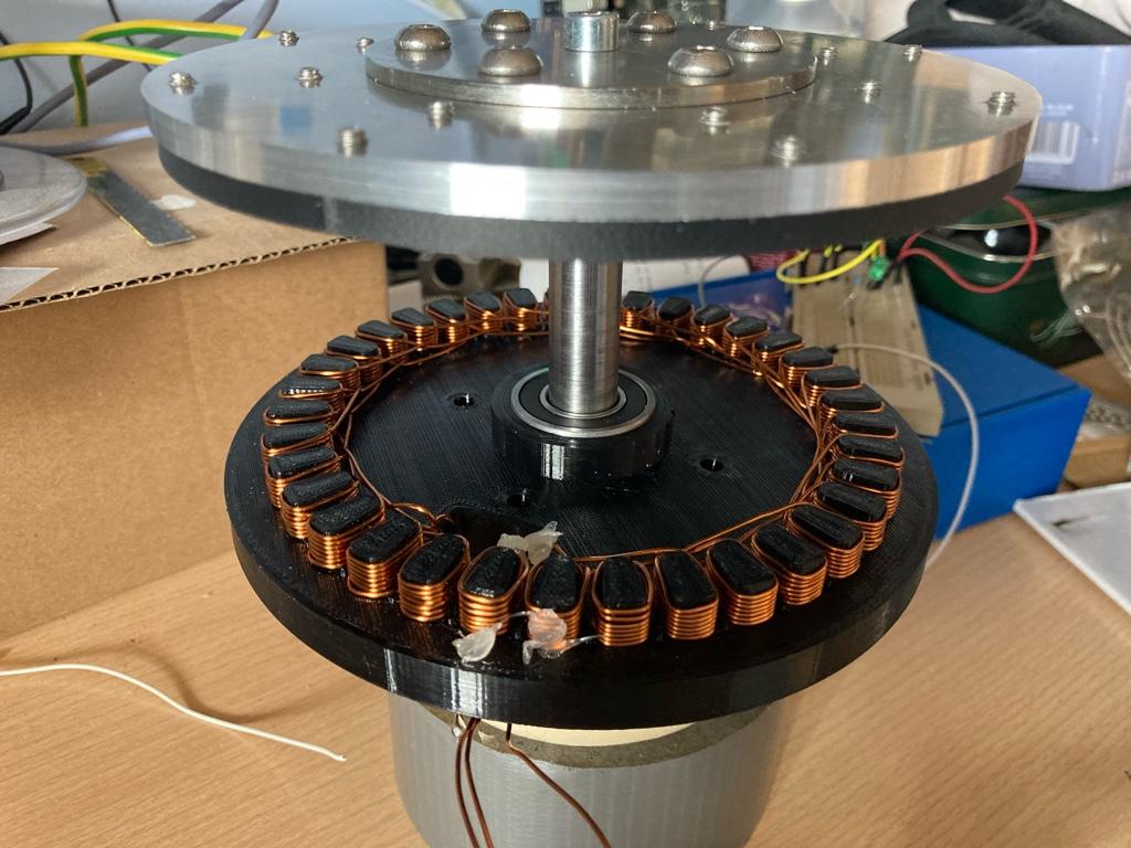
My plans are to make a small motor (like the one you see on the pics, the rotor has 150mm outside diameter), make sure it works the way it should and keep improving from there (and maybe scaling it up). I would love to build a small buggy/crosskart with my own electric motor.
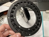
I've been working on it for a few days, first I searched for a supplier for the magnets and picked a reasonable size to start designing, I went with 24 magnets of 10x10x5mm (N42 grade) and 24 magnets of 10x5x3mm (N45 grade), all of them arranged in a Halbach pattern (24 poles). Once I had that I made a rough design of the 3D printed piece that would allocate all the magnets distributed evenly and printed it with polycarbonate carbon fiber (5.4 mm of total thickness), here's the part:
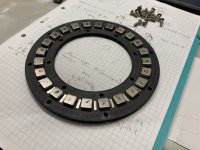
And all the magnets mounted (almost at the limit of being completely pulled away):
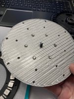
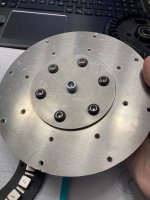
When I got the magnets all mounted I had to design the backplate, I made a drawing in AutoCAD and machined on my MPCNC out of aluminum and threaded all the necessary holes to mount the countersunk screws, also I made the center piece out of stainless steel that bolts the aluminum plate to the axle. Notice that the magnets are pushed against the aluminum plate, the thickness of the bottom part of the 3d printed piece is 0.4 mm, I did some tests with half of that but wasn't strong enough to hold firmly the magnets.
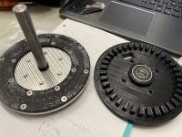
Once I had the rotating assembly done, I 3D printed the stator (36 slots) out of PETG, and embedded two 6002-2RS ball bearings onto it.
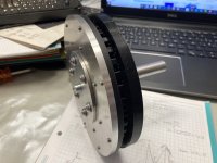
The air gap between the rotor and stator is about 0.6 mm.
That's all the progress so far, I'm currently waiting for the copper wire to start winding the stator, maybe the most practical way is to wind the coils in series but I still need to think about it.
All comments and suggestions will be greatly appreciated, I will try to post more about this project as I'm making progress with the machining and winding process.
PS: I got some suggestions from the workers of the electric motor shop about the windings, but it will be my first time winding a real motor, so maybe I will practice a bit before the real deal.
Thanks for reading.
Henry.
I've been into electric vehicles for a while, and after reading APL's and HalbachHero's threads I got some inspiration and decided to start tinkering about building an axial flux motor (and found out that i'm not the only one that likes this stuff
I'm currently studying mechanical engineering and I have a lot of interest on electric vehicles, I've built two electric go karts so far and going strong, also, I spend all my summers working on a electric motor maintenance and repair shop and I learned a lot working there.
My plans are to make a small motor (like the one you see on the pics, the rotor has 150mm outside diameter), make sure it works the way it should and keep improving from there (and maybe scaling it up). I would love to build a small buggy/crosskart with my own electric motor.
I've been working on it for a few days, first I searched for a supplier for the magnets and picked a reasonable size to start designing, I went with 24 magnets of 10x10x5mm (N42 grade) and 24 magnets of 10x5x3mm (N45 grade), all of them arranged in a Halbach pattern (24 poles). Once I had that I made a rough design of the 3D printed piece that would allocate all the magnets distributed evenly and printed it with polycarbonate carbon fiber (5.4 mm of total thickness), here's the part:

And all the magnets mounted (almost at the limit of being completely pulled away):

When I got the magnets all mounted I had to design the backplate, I made a drawing in AutoCAD and machined on my MPCNC out of aluminum and threaded all the necessary holes to mount the countersunk screws, also I made the center piece out of stainless steel that bolts the aluminum plate to the axle. Notice that the magnets are pushed against the aluminum plate, the thickness of the bottom part of the 3d printed piece is 0.4 mm, I did some tests with half of that but wasn't strong enough to hold firmly the magnets.


Once I had the rotating assembly done, I 3D printed the stator (36 slots) out of PETG, and embedded two 6002-2RS ball bearings onto it.


The air gap between the rotor and stator is about 0.6 mm.
That's all the progress so far, I'm currently waiting for the copper wire to start winding the stator, maybe the most practical way is to wind the coils in series but I still need to think about it.
All comments and suggestions will be greatly appreciated, I will try to post more about this project as I'm making progress with the machining and winding process.
PS: I got some suggestions from the workers of the electric motor shop about the windings, but it will be my first time winding a real motor, so maybe I will practice a bit before the real deal.
Thanks for reading.
Henry.


