HI FRIENDS IS NOT JUST A THEORY, I AM WORKING, ACTUALLY, WITH SMALL DC CONVERTERS FROM MURATA, OR TI DC -TO DC. NOT CAPACITORS, YET, MAY BE LATER I WILL INCORPORATE ULTRACAPS TO THE POWER BANK. I NEED TO CHECK OUT BOTH, THE ONLY PROBLEM I HAVE IS TO RESOLVE THE POLARITY INCOMPABILITY, THE CELLS NEED TO BE CHARGED BY PACKS OF SIMILAR POLARITY AND FOLLOWING TO THE NEXT SIMILAR POLARITY. THE ONLY WAY IS TO USE LARGE DC DC CONVERTERS , 3/5AMPS TO USE ALL THE POWER OF THE BATTERY UNTIL GET CHARGED AGAIN, IS THE ONLY WAY TO GET ALL HIS ENERGIE. THE LINES AND VALUES WILL BE CONTROLLED BY AN IC, PIC OR SIMILAR. MOST MANUFACTURESRS ARE WORKING ON FLYBACK TRANSFORMERS, ALL THE PASSIVE SYSTEMS JUST WASTE ENERGIE ON HEAT, IS NOT COOL; ACTUALLY GERMANS, AUSTRALIANS ARE WORKING ON SIMILAR CONCEPTS BUR THEY USE FEW AMP FOR BALANCING, I PROJECT TO USE NO LESS THAN 3 AMPS, AND ALSO WITH THE THE HELP OF REGENERATIVE FUNCTION IS POSSIBLE THIS CONCEPT IS POSSIBLE. MINE HAVE A BIG SOLAR PANNEL ONTHE ROOF( 320W) WITH SATELLITE SOLAR CELLS. iS NOT A CHAEP PROJECT BUT LOOK AT THE PRICE OF CSIRO AND GERMANS BMS. MANUFACTURERS !!. ATMEL USE SIMILAR CONCEPT, BUT ONLY BALANCE 1 AMP.; LINEAR ALSO BUT THEIR SISTEMS DO NOT WORK WITH LIFEPO4, . THEIR FAST CHARGING CAPACITY MAKES DECIDE TO BUILD UP MI OWN SYSTEM WITH TAHT BAT. CHEMISTERY. IS NOT OUT OF MI POSSIBLITY´S AND NOT MORE EXPENSIVE THAN ANY OF THE REAL EFFICIENT ONES. i AM NOT ENGENEER AND I NEED SOME HELP TO RESOLVE THE PLARITY AND WHERE TO MOUNT THE DIODES, WELL I AM WORKING ON IT....

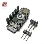
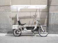
 :x [attachment=1]ti 5430.JPGHi, freinds 3 years ago i started up developping a solar powered e-bike prototype. On that way i learned a lot about batteries, charging and balancing, the worst and darkest side of the process. TIred about passive chineese bms systems i decided to built up using mi limited electronics knowledge an efficient active balancing system based on multiple little dc-dc transformers mounted on flyback system. I have actually choiced two types of them from murata and and usin ti dc dc converters 60v to 3.8. But i have a problem withe shematics originally disigned with transistor´s switches; now directly using small dc converters for each cell. The BIGGEST problem is how to resolve that problem making them working at the same time avoiding the polarity problems. I need help on to resolve that shematics properly mounting the diodes to split the cells and charge/balancing them individualy , all enables and controls using 1 or 2 pics or Ic. Somebody can help me to solve that challenge, please.