
You are using an out of date browser. It may not display this or other websites correctly.
You should upgrade or use an alternative browser.
You should upgrade or use an alternative browser.
Electric Moped (Erider Wiring Diagram Needed)
- Thread starter spudman
- Start date
i don't know of one, and didn't see one in a quick search around the forum and the web.
what specifically did you need to know about it? perhaps we can help you figure it out without a diagram. (you will probably have to do some measuring with a multimeter on continuity or ohms, and possibly the dc voltage settings, depending on what has to be tested).
(i did add some info (Erider Wiring Diagram Needed) to your thread title to better attract the specific help you are after, since "electric moped" isn't sufficient to grab attention of the right readers that are just looking at thread titles).
amberwolf said:i don't know of one, and didn't see one in a quick search around the forum and the web.
what specifically did you need to know about it? perhaps we can help you figure it out without a diagram. (you will probably have to do some measuring with a multimeter on continuity or ohms, and possibly the dc voltage settings, depending on what has to be tested).
(i did add some info (Erider Wiring Diagram Needed) to your thread title to better attract the specific help you are after, since "electric moped" isn't sufficient to grab attention of the right readers that are just looking at thread titles).
Hi amberwolf, I have done all the wiring tests with a multimeter, Dc voltage, Ohms, and continuity too. I have had to go ahead and order a new Controller from Erider for the model 15 as I cant see why it wont run no more. it did have a dodgy grip throttle which I removed. I have never seen so many joins in the cable. bare wire was showing too. also some cowboy has wired a cable to back wheel motor which has 3 wires blue, brown, and yellow/green obviously AC cable. but it wasn't attached to anything, it was taped at the end and was stuck down with duck tape behind the controller. so now I have cut it off at the wheel. I did find it hard to test wires going to back wheel as you have to stick end of pointed probe into wires, and the 5 hall sensor wires are so thin, so is there another way of checking continuity, as I cant think how. how all this started was I was driving along when speed dropped down. it wasn't the battery as its new. when I pushed it all way home and opened throttle wheel wouldn't go round. but if I kept throttle open then moved wheel it was ok then spinning
I forgot to mention I would prefer a thumb throttle with batt indicator and a key, but atm I bought a cheap thumb throttle to use for testing. it has 3 wires black, green, and red, but on a thumb throttle with a batt indicator and key there is 5 wires same as other but a blue and yellow wire. where would the blue and yellow wire attach to to make it work. mind you I am a bit ahead of myself LOL as moped isnt running yet, but hope the new controller will fix it
can you post the diagram you came up with while doing this? it will help us help you ensure all the wiring is present and correct, since at least some of it has apparently been changed by the previous owner.spudman said:Hi amberwolf, I have done all the wiring tests with a multimeter, Dc voltage, Ohms, and continuity too.
based on that, there isn't going to be a diagram for it as it sounds like the previous owner rewired it. if they made a diagram for it when they did this, then you could get that from them, but an original diagram wouldn't likely help you figure out the problem.it did have a dodgy grip throttle which I removed. I have never seen so many joins in the cable. bare wire was showing too. also some cowboy has wired a cable to back wheel motor which has 3 wires blue, brown, and yellow/green obviously AC cable. but it wasn't attached to anything, it was taped at the end and was stuck down with duck tape behind the controller.
if you want the original diagram so you can rewire it back to original, then i don't know where to find one, unless you can find someone with an unmodified one that's willing to draw one up for you, if the seller / manufacturer doesn't supply diagrams (most don't).
if the wires from the motor werent' connected to anything, the motor could not have operated. this means they had to be connected to the controller correctly, if it operated for you even once. so you should draw up exactly what all the wiring actually is, and what it was, so we can help you ensure it is correct.
I have had to go ahead and order a new Controller from Erider for the model 15 as I cant see why it wont run no more.
there are a lot of possible causes for that; we'll need to narrow down the specifics of what that means.
what, exactly and precisely, does "won't run no more" mean? is this different than the information i quoted below?
more detail is better.
how all this started was I was driving along when speed dropped down. it wasn't the battery as its new. when I pushed it all way home and opened throttle wheel wouldn't go round. but if I kept throttle open then moved wheel it was ok then spinning
did it run correctly for you when you first got it, and fail later? if so, what exactly and precisely happened between the time it worked and the time it didn't?
more detail is better.
based on the last part " opened throttle wheel wouldn't go round. but if I kept throttle open then moved wheel it was ok then spinning" it sounds like the signals from the hall sensors in the motor are not getting to the controller, or one of the sensors may have failed. it's unlikely to be the controller, since it does spin the motor if you manually get the wheel started.
setup the bike with the motor wheel off ground, with everything connected normally, including the controller to evertyhing it should be, including the motor's phase (3 thick wires) and hall (5 thin wires) and powered on, set your multimeter to 20vdc. black lead to battery negative.
red lead to red hall wire should read within a few percent of 5v.
for next three, hook up wire then watch meter lead while manually turning the motor wheel slowly.
red lead to yellow hall wire should read toggling between about 5v and about 0-1v.
red lead to green hall wire should read toggling between about 5v and about 0-1v.
red lead to blue hall wire should read toggling between about 5v and about 0-1v.
if any of those is different from the above, post what exactly you do get and we can go from there.
if it never worked right for you, then you may have to redo some or all of the wiring yourself to ensure it is correct and complete. even if you don't, you should draw up your own diagram as you test the wiring and/or replace it, so that you can refer to it later if you need to work on it.
for the problem you have, the only good way is to open the side of the motor and check the wires where they connect inside, especially if it was repaired by someone else before (as they may not have made good connections inside).I did find it hard to test wires going to back wheel as you have to stick end of pointed probe into wires, and the 5 hall sensor wires are so thin, so is there another way of checking continuity, as I cant think how.
if you post good clear pics of both sides of the motor, we can help you figure out how to open that motor; there are several ways they coudl have made it.
also, the most common failure point for hubmotor wiring is at the exit from the axle--if the axle end ever gets pushed or hit against anyth8ing, the wiring can be severed or damaged by the edges of the hole it comes out of. sometimes you can't see this damage but it is still there inside the insulation. to fix this you usually have to replace the wiring starting from inside the motor itself. this is probably what the original owner did, probably using an old power cord or extension cord because that wiring is usually at least as thick, and probably thicker, than the wiring that came out of the motor originally (if so it would be better than original).
I forgot to mention I would prefer a thumb throttle with batt indicator and a key, but atm I bought a cheap thumb throttle to use for testing. it has 3 wires black, green, and red, but on a thumb throttle with a batt indicator and key there is 5 wires same as other but a blue and yellow wire. where would the blue and yellow wire attach to to make it work.
that depends on your specific new throttle unit. they come in several wiring variations, with different ways of functioning for the switches (some of which will blow things up if hooked up wrong) so you will need it's wiring diagram to know where to hook up each wire. if you don't get a diagram with it, then you will have to open it up to trace where the wires go, and draw that up, so we can help you figure out where to hook it up.
to choose which version of throttle unit to get, what do you want the key to do? sometimes they are wired to turn 5v power on or off to the throttle itself. sometimes they turn the keyswitch/ignition ksi battery voltage on or off to the controller from the battery. sometimes this also turns on the battery meter in the unit itself, and sometimes that meter has a separate wire of it's own so it can stay on even if the bike is off.
which way do you want it to work?
Hi amberwolf thanks for your help
this is what someone on another bike forum told me to do, as its only a bike forum they suggested to go to this forum as its for mopeds etc
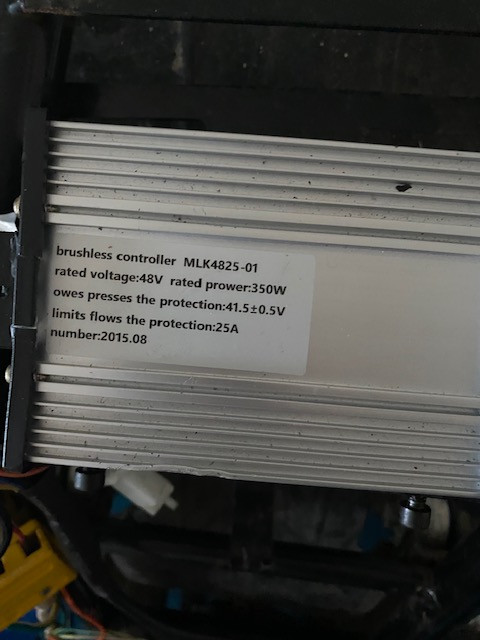
this is the controller I have atm
Also I dont think I have explained things right. at the back wheel there is 2 leads 1 lead is 8 wires 3 thick and 5 thin which obviously are phase and hall wires going to the controller
but who ever had moped before me had wire another cable to back wheel which had just 3 thick wires Blue, Brown, and green/yellow. obvious a standard house cable but the other end was taped off and was just stuck behind controller, and not attached to anything
Yes it ran ok but only for about 6 miles, then battery went down to 5KM/h I rang the seller but he wouldnt reply. anyway long story I asked on this other forum. they said what controller is it. and its a 350W 25A so obviously the battery on moped wasnt right so I had to buy new battery a 48V 30Ah one and all was fine. then 1 day i was driving along and speed slowed right down to about 10 Km/h so I ended up pushing it home. and when you open throttle motor in back wheel wont turn but if I kept throttle open then just move back wheel then it would run ok spin. anyway I decided to check this grip throttle. and like i said have never seen so many joins, plus now its unusable. so I bought a cheap thumb throttle with 3 wires green, black and red same as on controller wires so I temp joined them. but wheel dont even turn now, when I open throttle, or spin when I move wheel whilst open throttle.
I will have to do these tests when I have connected new controller.
I will post some pics below of the leads etc to controller

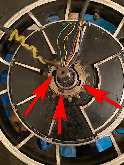
this is back wheel the cable with yellow line is that other cable previous owner added but its not connected to anything at controller end so I have now cut that off. also how can that nut be unscrewed where red arrows show.
can you post the diagram you came up with while doing this? it will help us help you ensure all the wiring is present and correct, since at least some of it has apparently been changed by the previous owner.
this is what someone on another bike forum told me to do, as its only a bike forum they suggested to go to this forum as its for mopeds etc
The only other thing to do is test the controller to make sure it hasn't blown a mosfet by the way of an ohms/resistance test so disconnect the battery as we do not want voltage interference.
Test the controller phase wires by disconnecting the battery and select 200ohms on the DC dial, probe the Black wire (input wire from the battery) against each of the thicker motor phase wires Blue, Yellow & Green. One should get three results all about the same 7k ohms to 15kohms, if any result is way out from the others then the controller is faulty.
Then test the thick Red wire against the same three coloured wires again the results should all be the same but likely very different from before, any result from this last test that reads zero means a faulty controller.
my results back to him was
input black to blue = 0.98 0hms
input black to green=0.91
input black to yellow= 10.0v
thick red to blue =16.6 ohms
thick red to green=16.2
thick red to yellow=16.3
this is the controller I have atm
Also I dont think I have explained things right. at the back wheel there is 2 leads 1 lead is 8 wires 3 thick and 5 thin which obviously are phase and hall wires going to the controller
but who ever had moped before me had wire another cable to back wheel which had just 3 thick wires Blue, Brown, and green/yellow. obvious a standard house cable but the other end was taped off and was just stuck behind controller, and not attached to anything
did it run correctly for you when you first got it, and fail later? if so, what exactly and precisely happened between the time it worked and the time it didn't?
Yes it ran ok but only for about 6 miles, then battery went down to 5KM/h I rang the seller but he wouldnt reply. anyway long story I asked on this other forum. they said what controller is it. and its a 350W 25A so obviously the battery on moped wasnt right so I had to buy new battery a 48V 30Ah one and all was fine. then 1 day i was driving along and speed slowed right down to about 10 Km/h so I ended up pushing it home. and when you open throttle motor in back wheel wont turn but if I kept throttle open then just move back wheel then it would run ok spin. anyway I decided to check this grip throttle. and like i said have never seen so many joins, plus now its unusable. so I bought a cheap thumb throttle with 3 wires green, black and red same as on controller wires so I temp joined them. but wheel dont even turn now, when I open throttle, or spin when I move wheel whilst open throttle.
setup the bike with the motor wheel off ground, with everything connected normally, including the controller to evertyhing it should be, including the motor's phase (3 thick wires) and hall (5 thin wires) and powered on, set your multimeter to 20vdc. black lead to battery negative.
red lead to red hall wire should read within a few percent of 5v.
for next three, hook up wire then watch meter lead while manually turning the motor wheel slowly.
red lead to yellow hall wire should read toggling between about 5v and about 0-1v.
red lead to green hall wire should read toggling between about 5v and about 0-1v.
red lead to blue hall wire should read toggling between about 5v and about 0-1v.
I will have to do these tests when I have connected new controller.
I will post some pics below of the leads etc to controller
this is back wheel the cable with yellow line is that other cable previous owner added but its not connected to anything at controller end so I have now cut that off. also how can that nut be unscrewed where red arrows show.
Note that blown FETs don't normally cause the symptom of the motor not spinning on it's own, yet still being able to start it manually and have it keep going via the controller.spudman said:this is what someone on another bike forum told me to do, as its only a bike forum they suggested to go to this forum as its for mopeds etc
Blown halls, or the hall signals not making it to the controller *can* cause this, especially if it is only one of the three.
The only other thing to do is test the controller to make sure it hasn't blown a mosfet by the way of an ohms/resistance test so disconnect the battery as we do not want voltage interference.
Test the controller phase wires by disconnecting the battery and select 200ohms on the DC dial, probe the Black wire (input wire from the battery) against each of the thicker motor phase wires Blue, Yellow & Green. One should get three results all about the same 7k ohms to 15kohms, if any result is way out from the others then the controller is faulty.
Then test the thick Red wire against the same three coloured wires again the results should all be the same but likely very different from before, any result from this last test that reads zero means a faulty controller.
my results back to him was
input black to blue = 0.98 0hms
input black to green=0.91
input black to yellow= 10.0v
thick red to blue =16.6 ohms
thick red to green=16.2
thick red to yellow=16.3
Do you mean 10.0v, or 10.0 ohms? If you mean v, then that means the meter was set to the wrong setting, and there was still power to the controller (which can damage the meter if it was set to ohms).
Were the wires tested with the motor connected? If they were, then the results aren't useful, because you're just measuring wire resistance to and from the motor, plus the motor windings, not the FETs.
If you were testing the FETs with the motor disconnected from the controller, then the FETs are all completely shorted, and the controller has failed. If this is the case then with the motor connected you would not be able to roll the bike's motor wheel normally (very very hard to turn it, as if the brakes were stuck on), because the FETs are shorting the phases, and this locks up the motor.
Additionally, if the meter is set to 200ohms, you should read OL on every FET, because at that range it can't read the normal range of resistance of the FETs (which should be at least as high as they stated). You would need to use the 20kohm or 200kohm range or higher to test the FETs normal resistance.
Never seen that one before, but it is probably a typical low-power brushless controller for a 36v battery. It has a 25A maximum current limit, and can sustain 350w (which at 36v is less than 10A continous, meaning that depending on it's design and how much cooling it gets, it could be damaged by riding up steep hills, etc., as that would force it to handle more than double it's power rating). The motor may be able to handle more than that, depending on it's type and design (this is common).this is the controller I have atm
Also I dont think I have explained things right. at the back wheel there is 2 leads 1 lead is 8 wires 3 thick and 5 thin which obviously are phase and hall wires going to the controller
but who ever had moped before me had wire another cable to back wheel which had just 3 thick wires Blue, Brown, and green/yellow. obvious a standard house cable but the other end was taped off and was just stuck behind controller, and not attached to anything
So there are two thick cables going into the motor axle? (assuming this motor uses the common method of a hollow axle for the wires to go into) The original 8 wire, plus a new 3 wire? There is not normally room for this unless they have seriously modified the axle (which would weaken it and could cause it to break under stress).
If the new 3 wire cable doesn't actually go into the motor and is not connected to the motor or anything else, then I wouldnt' worry about it.
It sounds like they might have been experimenting, or attempting to upgrade the phase wires for better current flow to the motor (which can sometimes help with getting a little extra power out of it, when using high power controllers and motors (which yours is not).
If the added 3-wire cable ever gets shorted even just a little bit (water, corrosion, etc) from any wire to any other within the cable, it could cause the controller to misbehave or even be damaged, depending on the severity of the short.
Battery meters don't normally read in km/h. They usually read in Wh, Ah, or V. Which one do you mean?Yes it ran ok but only for about 6 miles, then battery went down to 5KM/h
Or do you mean that while riding, the speed dropped down to 5km/h?
I'm sorry for asking so many questions like this, but terminology is *very* important when troubleshooting these things, because without the right terms, it's impossible to know which thing might be wrong, and in many cases even which thing is being discussed.
")
How was the battery obviously not right? Please give complete details on what battery it originally had, including what type it is (lead, SLA, AGM, lithium, Li-ion, LiFePO4, NiMH, etc etc). Also give complete details on what the new battery is. It could be very important to troubleshooting the problem(s) your bike has.they said what controller is it. and its a 350W 25A so obviously the battery on moped wasnt right so I had to buy new battery a 48V 30Ah one and all was fine.
What does "all was fine" mean? Does this mean that the bike now rode normally with no problems? If so, how long did it operate normally before the next problem? Was there ever any water, rain, splashes, etc? (this can degrade an already poor connection)
If it suddenly slowed down, just like the first time (but to a different speed), it is very likely still the same problem, which is very likely a bad connection from one of the motor halls to the controller. If so, it is intermittent, and may be difficult to find, but it is usually at the connector itself between the motor and the controller. At that spot, the wires are crimped into pins, and those crimps can be poorly made, or done too far and actually cut the wire inside the insulation (you can't see either of these problems easily), or the pins may not mate with the other side of the connector well, where either one pushes another out of it's shell (not fully seated), or the barrel or fingers of one side's pin doesn't really fit well inside the other side of the connector.then 1 day i was driving along and speed slowed right down to about 10 Km/h so I ended up pushing it home. and when you open throttle motor in back wheel wont turn but if I kept throttle open then just move back wheel then it would run ok spin.
It's a very common problem with many connector types, and wiring / connections are the cause of almost all problems with any electric device of any kind.
That could mean it's the wrong kind of throttle, or taht it is wired wrong. Colors do not always match between devices, even of the same brand; there are some common combinations but theyr'e far from universal; some wiring color combinations are essentially random.anyway I decided to check this grip throttle. and like i said have never seen so many joins, plus now its unusable. so I bought a cheap thumb throttle with 3 wires green, black and red same as on controller wires so I temp joined them. but wheel dont even turn now, when I open throttle, or spin when I move wheel whilst open throttle.
Do you have notes on what the original wiring was for anything you have had to fix or change? If so, I would recommend putting that wiring back the way it was and retesting.
Also, there are two basic types of throttle. One is a Pot(entiometer), and the other is a Hall. They're not interchangeable on all controllers. Pot throttles are much more common in grip throttles, and rare in thumb types. You can test which one yours are using your multimeter.
Disconnect throttle from system, then set meter to 20kohm. Black lead on black wire of throttle, then red on red wire. If it's hall, it will probably read OL. If it's pot, it'll probably read 5kohm to 10kohm. Move red wire to third throttle wire (usually green or white). If hall, it'll probably read OL. If pot, it'll usually read around 0ohms, or very low. Turn throttle and for a hall it won't change but for pot this will go up, until it reads near the max reading you got on the other wire.
Now test the other throttle. Post your results for both here. If they are different, then they are different types, and yoru controller may error out with the wrong one (sometimes one can be made to work on the other, sometimes not).
I will have to do these tests when I have connected new controller.
You can test using the old controller; I highly recommend doing so. It doesn't matter if it "works" or not, as long as it provides the 5v to the halls. The reason for testing with the old controller is to see if the problem lies in the controller, the motor, or the wiring, so you know where the problem is (or was) and will know for sure that it is fixed, and not still going to continue to happen randomly to you.
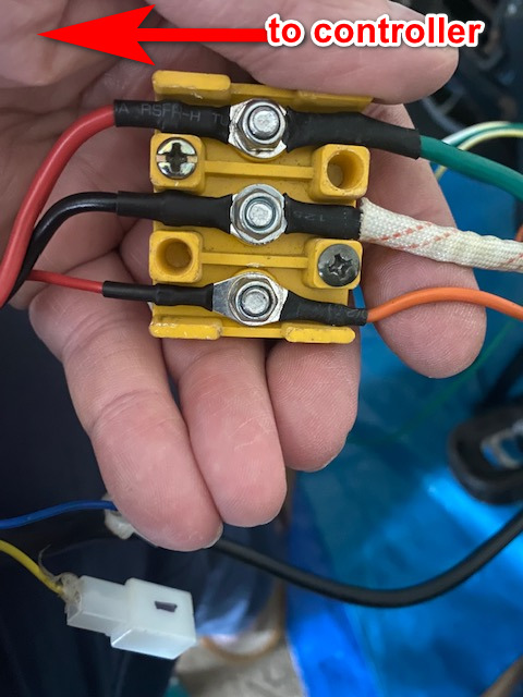
This looks like battery power for the large black and red leads. Is that what this one goes to?I will post some pics below of the leads etc to controller
This looks like typical motor phase wiring (although colors don't always match like this one does; it's very common for them not to).
I see how they fit the wiring in there; it's a pretty bad idea to do it that way--they took the insulating jacket off the original motor cable, which means that the wires are now rubbing directly on the edges of the axle hole, and means it is very possible that one or more of the wires is damaged and either shorting to other wires, or to the axle which is also connected to the frame of the whole bike (whcih may be wired ot battery negative, ground, for any lighting it has). Or the wires could be broken open inside their insulation (but the shorting is much more common). This usually happens right at the point the wires enter the axle, or where they come out of it inside the motor itself.this is back wheel the cable with yellow line is that other cable previous owner added but its not connected to anything at controller end so I have now cut that off. also how can that nut be unscrewed where red arrows show.
Also, they are probably no longer anchored inside the axle (the jacket does this normally), so they could have ripped loose inside the motor. The hall test I posted before will show if they are still reading, which means they are still connected; if any test just reads 5v all the time then that hall wire is probably ripped off the internal motor wires.
I would recommend opening the motor and removing the add-on cable entirely, then pulling the original motor cable thru the axle (use a water-based lube, or vaseline, on the jacket so it is easier to get thru the hole), until you have at least a half inch or more of jacketed cable inside the motor as well as all that length of unjacketed wire. This will protect the motor cable from a number of types of damage. If none of the unjacketed wires are damaged yet, you can then just tie them down to internal motor support brackets to keep them out of the way of the spinning covers. If they are too long, you may have to redo the connections one at a time (to ensure they don't get mixed up), but don't do this unless you have to, or the connections are poor or broken already.
It is possible that all the wiring actually connects on the opposite side of the motor, which makes things a little easier if so. Then you can just unbolt the left side (the one not visible in the pic) cover bolts. Place the axle end on *this* side down on concrete, and push down on the rim and tire slowly, as hard as you can. This should push the other side's cover up and break loose any seal, so you can remove it. When you stop pushing, the motor inside will be pulled back into the housing by the magnets very hard, so don't let your fingers get in the way of this happening! The side covers can be fragile in this direction, so don't whack it or bend it or you'll need a new motor (you probably can't buy a side cover for it if you break one).
The side cover should be left slightly up, enough to get something under it to lift it. If so, you can use two wide-surfaced pry bars (motorcycle tire levers, etc), to pry just the *edges* of the cover up gently, from opposing edges at the same time (you can break things if you do just one at a time, or else just not be able to lift it). When it is far enough to get your fingers under there, you can lift straight up with those while standing or kneeling on the tire.
Do not stick anything under the cover any farther than where the bolt holes are, or you can damage the motor windings.
If you have a 3-jaw gear puller you can use that instead of pry bars, and that's even better and easier. (the dimple in the center of the axle is made for this purpose).
If the connection points for the motor are not under the cover on the other side, then tehy are under the cover on this side, and then you'd have to take this cover off to get to them, same process as other side but harder because the wiring may be in the way. If so, cut off the addon cable right at the axle (avoid damaging the original wires!) to get it out of the way.
Hi again amberwolf
Yes its 10.0ohms not v
Yes as I have not looked inside back wheel
Well I contacted Erider and said the controller says 350W and 25A on it and they said yes its the right one, But then just because its right one maybe not same as Eriders Original I dont know until new one arrives, But like I said I have ordered a new controller, which I think has arrived but as I was out when post came I now have to go to sorting office Tuesday to collect it
Yes there was 2 thick cables going into the motor, and It seems there is a groove where they go into wheel. I exposed those wires like phase and hall wires when I was testing continuity, But have now sealed them in thick rubber and cable ties I have now also cut that other cable off near axle as like i said it wasn't attached to anything
Yes I mean speed dropped to 5 Km/h


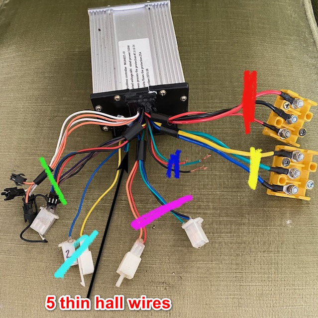
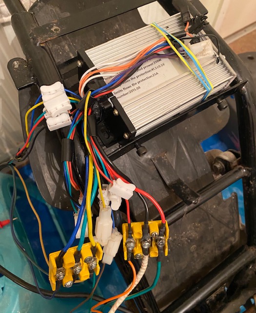
Here is the old controller below the green mark those are not used, the light blue are but dont know what they for, I think brake cables the 2 pink ones are for an Alarm. the blue ones are for the throttle, the yellow are for the phase 3 thick wires.
Im a bit confused what you mean above when you say powered on do you mean connect battery and turn on ignition.
where is battery negative.
red lead to red hall wire etc. but how can I check them if they are covered or do you mean stick pointed end of probe into wires
I forgot to mention the seller who done me down was charging up the old battery through the discharge port instead of charge port which is the jack plug in picture below the discharge is marked in yellow square and is a IEC kettle type plug
my results back to him was
input black to blue = 0.98 0hms
input black to green=0.91
input black to yellow= 10.0v
thick red to blue =16.6 ohms
thick red to green=16.2
thick red to yellow=16.3
Do you mean 10.0v, or 10.0 ohms? If you mean v, then that means the meter was set to the wrong setting, and there was still power to the controller (which can damage the meter if it was set to ohms).
Yes its 10.0ohms not v
Were the wires tested with the motor connected? If they were, then the results aren't useful, because you're just measuring wire resistance to and from the motor, plus the motor windings, not the FETs.
If you were testing the FETs with the motor disconnected from the controller, then the FETs are all completely shorted, and the controller has failed. If this is the case then with the motor connected you would not be able to roll the bike's motor wheel normally (very very hard to turn it, as if the brakes were stuck on), because the FETs are shorting the phases, and this locks up the motor.
Yes as I have not looked inside back wheel
Never seen that one before, but it is probably a typical low-power brushless controller for a 36v battery. It has a 25A maximum current limit, and can sustain 350w (which at 36v is less than 10A continous, meaning that depending on it's design and how much cooling it gets, it could be damaged by riding up steep hills, etc., as that would force it to handle more than double it's power rating). The motor may be able to handle more than that, depending on it's type and design (this is common).
Well I contacted Erider and said the controller says 350W and 25A on it and they said yes its the right one, But then just because its right one maybe not same as Eriders Original I dont know until new one arrives, But like I said I have ordered a new controller, which I think has arrived but as I was out when post came I now have to go to sorting office Tuesday to collect it
So there are two thick cables going into the motor axle? (assuming this motor uses the common method of a hollow axle for the wires to go into) The original 8 wire, plus a new 3 wire? There is not normally room for this unless they have seriously modified the axle (which would weaken it and could cause it to break under stress).
If the new 3 wire cable doesn't actually go into the motor and is not connected to the motor or anything else, then I wouldnt' worry about it.
It sounds like they might have been experimenting, or attempting to upgrade the phase wires for better current flow to the motor (which can sometimes help with getting a little extra power out of it, when using high power controllers and motors (which yours is not).
Yes there was 2 thick cables going into the motor, and It seems there is a groove where they go into wheel. I exposed those wires like phase and hall wires when I was testing continuity, But have now sealed them in thick rubber and cable ties I have now also cut that other cable off near axle as like i said it wasn't attached to anything
Yes it ran ok but only for about 6 miles, then battery went down to 5KM/h
Battery meters don't normally read in km/h. They usually read in Wh, Ah, or V. Which one do you mean?
Or do you mean that while riding, the speed dropped down to 5km/h?
Yes I mean speed dropped to 5 Km/h
this other site said what controller is it. and its a 350W 25A so obviously the battery on moped wasn't right so I had to buy new battery a 48V 30Ah one as bike wasnt running ok as with old battery it kept stopping. I have posted a picture of old battery below. I was told to test the BMS pins etc all was good. But the old battery was only 15a and they said that's my problem as controller says 25a it was a lithium one. the new battery is 48V 30Ah lithium
How was the battery obviously not right? Please give complete details on what battery it originally had, including what type it is (lead, SLA, AGM, lithium, Li-ion, LiFePO4, NiMH, etc etc). Also give complete details on what the new battery is. It could be very important to troubleshooting the problem(s) your bike has.
Here is the old controller below the green mark those are not used, the light blue are but dont know what they for, I think brake cables the 2 pink ones are for an Alarm. the blue ones are for the throttle, the yellow are for the phase 3 thick wires.
setup the bike with the motor wheel off ground, with everything connected normally, including the controller to evertyhing it should be, including the motor's phase (3 thick wires) and hall (5 thin wires) and powered on, set your multimeter to 20vdc. black lead to battery negative.
red lead to red hall wire should read within a few percent of 5v.
for next three, hook up wire then watch meter lead while manually turning the motor wheel slowly.
red lead to yellow hall wire should read toggling between about 5v and about 0-1v.
red lead to green hall wire should read toggling between about 5v and about 0-1v.
red lead to blue hall wire should read toggling between about 5v and about 0-1v.
if any of those is different from the above, post what exactly you do get and we can go from there.
Im a bit confused what you mean above when you say powered on do you mean connect battery and turn on ignition.
where is battery negative.
red lead to red hall wire etc. but how can I check them if they are covered or do you mean stick pointed end of probe into wires
I forgot to mention the seller who done me down was charging up the old battery through the discharge port instead of charge port which is the jack plug in picture below the discharge is marked in yellow square and is a IEC kettle type plug
What does "Yes" mean in reference to the above? There are two options provided, so "yes" implies both are true, but they cannot be.spudman said:Were the wires tested with the motor connected? If they were, then the results aren't useful, because you're just measuring wire resistance to and from the motor, plus the motor windings, not the FETs.
If you were testing the FETs with the motor disconnected from the controller, then the FETs are all completely shorted, and the controller has failed. If this is the case then with the motor connected you would not be able to roll the bike's motor wheel normally (very very hard to turn it, as if the brakes were stuck on), because the FETs are shorting the phases, and this locks up the motor.
Yes as I have not looked inside back wheel
Knowing which way the test was done will tell us if the test results were valid or not. (if they're not valid, they're not useful, as they dont' tell you anything at all about the controller having a problem or not).
If the test results are not valid (because the motor was still connected to the controller at the phase wires), then to get valid results you would need to retest the controller FET resistance with the motor not connected to the controller at the phase wires, by unbolting them. However, based on the symptoms reported so far, I don't think there is anything wrong with the FETs.
For instance, if the FETs do have the readings you got, then the wheel cannot be powered at all by the controller (because the FETs are blown and internally shorted and can't function), and is nearly stuck, feels almost jammed in place, very hard to turn at all by hand and very hard to roll the bike. If that's not the case, the readings can't be correct.
Yes there was 2 thick cables going into the motor, and It seems there is a groove where they go into wheel. I exposed those wires like phase and hall wires when I was testing continuity, But have now sealed them in thick rubber and cable ties I have now also cut that other cable off near axle as like i said it wasn't attached to anything
Did you insulate the individual wires of the add-on cable? If not, then since they are almost certainly connected to the phase windings inside the motor, there is a risk of them shorting together and blowing up your controller (new or old), as well as causing you sudden braking while riding (shorting phases together causes the motor to act as a brake).
If you haven't insulated them, you can test if they are connected to the windings by setting your multimeter to 20ohms, then using black lead on the exposed wire of the first of the addon wires. Red lead to any of the 3 ring terminals (doesn't matter which; they're all connected via the windings inside the motor to each other) of the motor phase wires at the bolt-together junctions. You should read very low ohms, if that addon wire is connected to one of the phase windings inside the motor. If it is not connected, you will see OL on the screen. Same for each of the other two addon wires.
If none of the addon wires is connected to the phase wires, then you can ignore those addon wires. If they are connected, then they need to be insulated, or they need to be removed from the motor to prevent future unexpected problems.
If this was a very sudden drop, not gradual, it usually means one of these things:Yes I mean speed dropped to 5 Km/h
1: there is a connection problem between the batteries and the controller, causing a big voltage drop
2: the controller has a two-level LVC, so that if the batteries drop below a certain point, it drops the speed of the bike to lower demand on the battery and prevent shutdown of the battery or damage to it.
3: something went wrong with the motor halls or hall connections, and the controller didn't know the rotation speed or direction of the motor so it defaulted to a slower speed to prevent problems.
4: Somethign went wrong with the addon wire connections inside the motor, or that cable somewhere along it's length, allowing a very slight interconnection between phases, causing the controller to protect itself.
Please note that 30Ah is just a capacity. 15A is a current limit. They look similar because the both have A in them, but A is amps, and Ah is amp-hours, and they are completely different things, and cannot be compared.this other site said what controller is it. and its a 350W 25A so obviously the battery on moped wasn't right so I had to buy new battery a 48V 30Ah one as bike wasnt running ok as with old battery it kept stopping. I have posted a picture of old battery below. I was told to test the BMS pins etc all was good. But the old battery was only 15a and they said that's my problem as controller says 25a it was a lithium one. the new battery is 48V 30Ah lithium
To compare their capabilities, you have to look at the A rating of the new battery.
If you want to compare capacities, you have to look at the Ah rating of the old battery, which isn't marked on the BMS, so it would have to be on the label of the battery itself, probalby under the duct tape on a sticker on the blue shrinkwrap. It may not be readable anymore, though. In that case, sometimes comparing physical size can give a general idea, since more capacity at the same voltage usually takes proportionally more volume. so if your new 30Ah battery is twice as large physically as the one you got with the bike, it will probably be twice the capacity. If it is about the same size, then it is about the same capacity.
The old battery picture shows a much smaller battery than what actually came with the bike from the manufacturer; the tray is the type meant for SLA (AGM, lead) batteries. I would guess from the BMS picture that the battery you got with the bike was a Li-Ion battery of some kind, based on the 13s 48v 3.7v information, though it doesn't show what exactly it is.
the 15A rating is actually fine for your controller, generally, because your controller can only handle 10A continuous anyway. The 25A rating on the controller is just for a few seconds at a time, and the BMS is probably able to handle that much for that long. If you are using more than 15A for long enough, the BMS would just shut off it's output and the bike would turn off, protecting the battery.
The 5A rating is typically the charging current rating. Note that I couldn't fully translate the chinese text on teh sticker, so I can't guarantee that's what it says, but that is normal for a small battery like this.
Without testing your old battery at the time the slowdown problem happens, to see if it has a sudden extreme voltage drop compared to when it does not have the slowdown problem, it's not possible to say with certainty that it has anything to do with the problem. It's probably not the cause of the problem. When that kind of things happens in a battery with a BMS, the BMS usually just shuts the output off completely (as it would in any of it's protection modes).
It is possible, though not that common, for the BMS to have failed in a way that leaves it's output stuck on all the time, so it cannot protect the cells in the battery against overload or overdischarge. This you can test for if you like, so that you can use both batteries for longer range if you need to.
Unfortunately the picture of the controller wires and connectors isn't really very useful for determining the bike's wiring, because there is no "standard" for wire colors, connector types, etc. You can make guesses based on similar setups, but they're just guesses.Here is the old controller below the green mark those are not used, the light blue are but dont know what they for, I think brake cables the 2 pink ones are for an Alarm. the blue ones are for the throttle, the yellow are for the phase 3 thick wires.
My guess is that of the unknown wires, the orange ones or the white ones are "self learn" (when connected they cause the controller to relearn whcih halls and phases go together to make the motor work right with it, so when it spins the right direction you disconnect it and it's done), and the other pair are a speed limiter (which may limit when connected, or when disconnected). The blue/black/red is probably a PAS (pedal sensor). Don't know what the purple/brown/black is; or the separate blue and yellow. There are a number of possible things they could be, but if there is nowhere to connect them on the bike, I would simply not worry about them, as their functions wouldn't be used anyway.
If you want to know what the bike wiring actually is (without a diagram including all the modifications done by the previous owner), you have to trace it all out on the bike and draw it up, wire by wire. I wish there was a better answer that was easier. For the unknown never-connected controller wires, only guesses can be made (even opening it up won't tell you as the markings inside are not standardized either, and simple voltage/etc readings don't tell much either). Trying out different connections with them might tell you something, but it also risks damaging things if guesses are wrong, because of the different voltages available within the controller.
Yes, if ignition powers the bike on to make it run normally.setup the bike with the motor wheel off ground, with everything connected normally, including the controller to evertyhing it should be, including the motor's phase (3 thick wires) and hall (5 thin wires) and powered on, set your multimeter to 20vdc. black lead to battery negative.
red lead to red hall wire should read within a few percent of 5v.
for next three, hook up wire then watch meter lead while manually turning the motor wheel slowly.
red lead to yellow hall wire should read toggling between about 5v and about 0-1v.
red lead to green hall wire should read toggling between about 5v and about 0-1v.
red lead to blue hall wire should read toggling between about 5v and about 0-1v.
if any of those is different from the above, post what exactly you do get and we can go from there.
Im a bit confused what you mean above when you say powered on do you mean connect battery and turn on ignition.
The negative (usually black) wire of the battery. You can access this at the bolt together terminals where the battery connects to the controller. Using this point guarantees you are making a good ground connection for the readings. (other black wires may also be ground, but since we don't know what the wiring is for this bike, that can't be assumed when testing functionality).where is battery negative.
I have to make some assumptions since I'm not there and don't have detailed pics of the entire wiring path of the entire bike, but:red lead to red hall wire etc. but how can I check them if they are covered or do you mean stick pointed end of probe into wires
There is normally a connector between the controller and the motor wires for the halls. You would usually check at this connector. On your bike, based on the other connectors for your controller, this is going to be either a black or white connector that looks like the other ones, with all five hall wires in it, that is open on the back so you can stick the meter probe into it and touch the pin from the back.
If you have no connector, then it is probable that the previous owner cut the connector off and direclty spliced the wires together, so you could remove the tape / etc they put over the splices, and test at those points.
If there weren't any splices or connectors, it doesn't matter, because you will have to splice them yourself since they're now cut off the old controller and to test you will need to make new splices to the correct wires on either the old one or the new one, and can test at those splices.
That can be a problem, because it means the BMS cannot protect against overcharging, and cannot ensure the cells stay balanced. It is not likely but it is possible for the cells to be damaged by this over a long enough period, if they become unbalanced. If you read the same voltage on each cell at the BMS connector to the cells, for all 13 groups, then they are balanced. If they're differnet voltages, they're unbalanced, and leaving the pack on the charger, thru the charge port, can fix that over time. Can take weeks for one that is very badly unbalanced. If you need to test the old battery I can describe procedures for that.I forgot to mention the seller who done me down was charging up the old battery through the discharge port instead of charge port which is the jack plug in picture below the discharge is marked in yellow square and is a IEC kettle type plug
What does "Yes" mean in reference to the above? There are two options provided, so "yes" implies both are true, but they cannot be.
When you say was the motor connected but isn’t the motor always connected. In the back wheel I’m a bit confused with that question
When you say FETS do you mean MOSFETS
How do you mean with the motor not connected to the controller the motor is in the back wheel isn’t it and I have not opened back wheel
The back wheel turns ok by hand
What do you mean by add on wires
This is the new battery I have on moped
Yes the moped must of had 2 x 24v lead acid batteries as the case for it
I have ordered 5 sets of 5 wire connector black plugs for the 5 hall wires
No, it's not always connected (in that it is not normally hardwired to the controller). On your bike, the motor phase wires can be disconnected from the controller at that bolt-on connector block. This is what you would do before testing the FETs in the controller. (if you don't, you're just testing wire and motor resistance, not the FETs).spudman said:What does "Yes" mean in reference to the above? There are two options provided, so "yes" implies both are true, but they cannot be.
When you say was the motor connected but isn’t the motor always connected. In the back wheel I’m a bit confused with that question
<snip>
How do you mean with the motor not connected to the controller the motor is in the back wheel isn’t it and I have not opened back wheel
The hall wires can normally be disconnected from the controller at the plug between the two. If there is no plug then whoever had it before you removed it and spliced the wires together somewhere or took the controller apart and directly soldered the motor hall wires to it inside.
Yes. It's just a shorthand, very commonly used.When you say FETS do you mean MOSFETS
If you mean that it turns ok *while connected to the old controller*, then the FETs cannot be shorted, so the readings you got aren't valid. I would guess that your old controller probably works fine.The back wheel turns ok by hand
If you mean that it turns ok without being connected to the controller, that just tells you the wires are not presently shorted inside the motor or anywhere along the length of wire that comes out of it.
The wires that were added on by the previous owner.What do you mean by add on wires
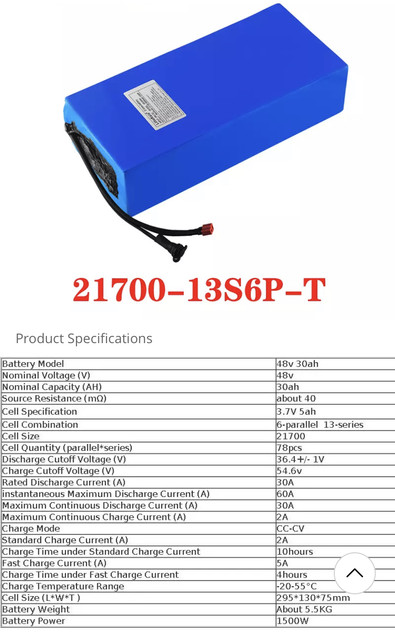
The specs show that it should be more than good enough to run the moped, with a continuous current capability of 30A, and max of 60A for a few seconds--but your 25A max 10A continuous controller won't even pull the continous limit, so no worries there.This is the new battery I have on moped
However, some of the specs don't match the claim of what the battery is. It probably doesn't mean anything, because people make mistakes like that all the time...but sometimes it means there is a problem.
For example, it says it has a standard charge of 2A, and would take 10 hours to charge, as well as a fast charge max of 5A, and would take only 4 hours to charge that way. That's not possible, because if it's a 30Ah battery, it would take *at least* 15 hours (a fair bit more, actually) to charge at only 2A, and it would take *at least* 6 hours (more, really) to charge at 5A. Either this information is wrong on the spec sheet, or they're lying about the capacity of the battery, and it is only 20Ah, not 30Ah. Most likely the charge time is just wrong.
Since they say it has 6p (6 parallel cells in each group) and each one is 5Ah, then that would make a 30Ah pack. If they are not wrong or lying about the cell capacity or number in parallel, then it's 30Ah...but the only way to actually find out would be to buy a wattmeter and install it so that you can monitor the battery as it empties during a ride, and don't recharge it until it completely runs out and shuts off, noting down the capacity used on each ride. (you could also do the test in one place, letting the bike run with wheel offground until the battery turns off, but that will take a lot longer).
It also says that hte maximum continuous charge current is only 2A, which means that it can't be fast charged at 5A or it would damage it. So one of the two is wrong.
These things may not matter...but they indicate that either someone didn't pay attention while writing that spec sheet or they didn't know what the battery could actually do, or they lied. Can't know which without testing (because if they *are* lying, or don't know, you can't trust what they may tell you if you ask them).
They don't generally come as 24v, so it probably had four 12v SLA. Depending on the space inside that case, they could have been 10-12Ah or 20-ish Ah (and these tend to weigh around a pound per Ah, or more!).Yes the moped must of had 2 x 24v lead acid batteries as the case for it
The Lithium batteries are generally a lot better than the SLA (more capacity for the same size and weight, last a lot longer, etc.). The only problem with lithium batteries is that cheap ones tend to not be made as good as the sellers say they are, or made of recycled used cells, etc. See above basic quick analysis of the spec sheet.
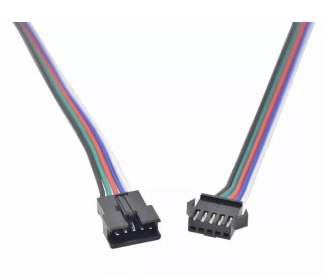
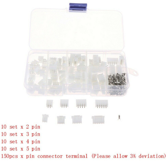
I have ordered 5 sets of 5 wire connector black plugs for the 5 hall wires
Are you going to splice those onto the existing wires? At the least, it will make it a lot easier to plug and unplug things.
BTW, if you need to know for future use, that connector type is JST-SM.
Hi again amberwolf I cant thank you enough for all your help its most appreciated, hope you had a nice xmas and a happy new year to you. Ive had my moped in my flat now over 2 months and I live in a 2 story flat Im on 1st floor, so 2 flights of stairs, so my brother helped me to take it up from my shed on the ground to my flat, as I have no where to do jobs on it. on the ground floor. plus its warmer in my flat lol.
so are you saying to disconnect the 3 phase wires from that bolt on block and can you just remind me now what I have to do in testing the FETs. as I can test them with the 3 wires unbolted from that block
Well there was a white plug a JST one I suppose it was, But there seemed to be a black wire loose so I cut the plug off the 5 hall wires, and have ordered these below but not here yet

I am going to use these connectors temp on old controller as dont want to solder wires if I have a new controller coming
Yes back wheel turns fine when moving it with pedals whilst its connected to the controller. But it wont if you connect battery and open throttle
Yes my mistake it must have been 4 x 12v LA batteries
Yes on the new controller I will splice old wires both sides of cut wire solder and shrink wrap them, then at least I can just plug them into that black connector. male to female JST_SM plugs
I have also ordered these will be handy
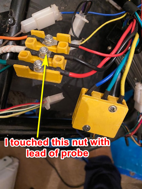
Hi I just did this test you said I touched black multimeter lead on this bit below is that right
and this is what I got I plugged in battery ignition on too
I found it very hard to hold both probes and turn back wheel via pedals
Btw would you know what this plug is suppose to be for on the Erider Model 15 if you go to 2.05 into this clip on youtube you will see that connection
https://www.youtube.com/watch?v=j80LS3IOd9s&t=222s
No, it's not always connected (in that it is not normally hardwired to the controller). On your bike, the motor phase wires can be disconnected from the controller at that bolt-on connector block. This is what you would do before testing the FETs in the controller. (if you don't, you're just testing wire and motor resistance, not the FETs)
so are you saying to disconnect the 3 phase wires from that bolt on block and can you just remind me now what I have to do in testing the FETs. as I can test them with the 3 wires unbolted from that block
The hall wires can normally be disconnected from the controller at the plug between the two. If there is no plug then whoever had it before you removed it and spliced the wires together somewhere or took the controller apart and directly soldered the motor hall wires to it inside.
Well there was a white plug a JST one I suppose it was, But there seemed to be a black wire loose so I cut the plug off the 5 hall wires, and have ordered these below but not here yet
I am going to use these connectors temp on old controller as dont want to solder wires if I have a new controller coming
If you mean that it turns ok *while connected to the old controller*, then the FETs cannot be shorted, so the readings you got aren't valid. I would guess that your old controller probably works fine.
Yes back wheel turns fine when moving it with pedals whilst its connected to the controller. But it wont if you connect battery and open throttle
They don't generally come as 24v, so it probably had four 12v SLA. Depending on the space inside that case, they could have been 10-12Ah or 20-ish Ah (and these tend to weigh around a pound per Ah, or more!).
Yes my mistake it must have been 4 x 12v LA batteries
Are you going to splice those onto the existing wires? At the least, it will make it a lot easier to plug and unplug things.
Yes on the new controller I will splice old wires both sides of cut wire solder and shrink wrap them, then at least I can just plug them into that black connector. male to female JST_SM plugs
I have also ordered these will be handy
Hi I just did this test you said I touched black multimeter lead on this bit below is that right
setup the bike with the motor wheel off ground, with everything connected normally, including the controller to evertyhing it should be, including the motor's phase (3 thick wires) and hall (5 thin wires) and powered on, set your multimeter to 20vdc. black lead to battery negative.
red lead to red hall wire should read within a few percent of 5v. 4.23
for next three, hook up wire then watch meter lead while manually turning the motor wheel slowly.
red lead to yellow hall wire should read toggling between about 5v and about 0-1v. 2.53
red lead to green hall wire should read toggling between about 5v and about 0-1v. 2.53
red lead to blue hall wire should read toggling between about 5v and about 0-1v. 2.53
and this is what I got I plugged in battery ignition on too
I found it very hard to hold both probes and turn back wheel via pedals
Btw would you know what this plug is suppose to be for on the Erider Model 15 if you go to 2.05 into this clip on youtube you will see that connection
https://www.youtube.com/watch?v=j80LS3IOd9s&t=222s
Yes, disconnect them, and test only the controller. (not the motor).spudman said:No, it's not always connected (in that it is not normally hardwired to the controller). On your bike, the motor phase wires can be disconnected from the controller at that bolt-on connector block. This is what you would do before testing the FETs in the controller. (if you don't, you're just testing wire and motor resistance, not the FETs)
so are you saying to disconnect the 3 phase wires from that bolt on block and can you just remind me now what I have to do in testing the FETs. as I can test them with the 3 wires unbolted from that block
This page
https://ebikes.ca/learn/troubleshooting.html
has good instructions on testing FETs and other components. This PDF
https://ebikes.ca/documents/BlownMosfets.pdf
is specific to this test.
The larger blocky white ones are not typically JST; they are usually a variation of Tamiya/Molex that I can never remember the name of.Well there was a white plug a JST one I suppose it was, But there seemed to be a black wire loose so I cut the plug off the 5 hall wires, and have ordered these below but not here yet
Assuming the wire colors used are standard (red = 5v, black = ground, yellow/green/blue = hall signal wires) then if the black wire was loose, then the hall sensors would not work (or would work incorreclty or intermittenly, and could cause exactly the problems you have described (depending on controller design). The black wire is the ground wire for all the sensors. Without that, there is no voltage reference for the controller to compare their output to, and no correct current path for the signals.
It's ok to just twist wires together for temporary connections, as long as you insulate them individually so they can't touch anything else or each other. Ignore the colors of the new wires, and make sure you match the color pattern it used to have (if it didn't match color for color; it's very common for the blue, green, yellow to not directly connect to the matching color on the other side, but instead to have say, blue to yellow, green to blue, yellow to green, etc). If you're not sure, just match the colors and you can at least still test the halls.I am going to use these connectors temp on old controller as dont want to solder wires if I have a new controller coming
If you have to test the motor itself later, in operation, then if it doesn't run right you might want to try the "self learn" wire pair (if that's what either that orange pair or white pair actually is for); if that's not possible or doesn't work then you may have to determine the correct color order; we'll work that out if necessary.
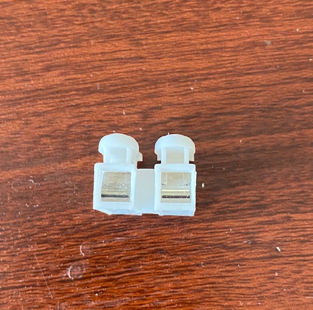
I'm not sure what those are for? Are they connectors the bike had on it?
Then the controller is still probably ok; it's probably either the throttle or the halls (or connection of one of those).Yes back wheel turns fine when moving it with pedals whilst its connected to the controller. But it wont if you connect battery and open throttle
They appear to be the JST-XH (or very similar) connectors. The pins that are not yet in shells must be crimped to the wires with the proper crimper in the right way, or they won't work right. Generally they can't be soldered because the solder tends to flow into the contact area and blocks proper mating/contact.I have also ordered these will be handy
There are a lot of crimpers out there (some examples https://www.amazon.com/jst-crimper/s?k=jst+crimper ) and most of them are not very good. I use an ancient Molex brand crimper but it isn't designed for the JST pins, it happens to work ok if I do it just right (but I screw up about half as many as I do right because of that). This video
seems to show how to do it
https://www.youtube.com/watch?v=iHm2yNMxj2s
but I did not watch the video.
This is the tool he links to
https://www.amazon.com/gp/product/B01N1RFZZ4/ref=as_li_qf_asin_il_tl?ie=UTF8&tag=makerfixes-20&creative=9325&linkCode=as2&creativeASIN=B01N1RFZZ4&linkId=7307eecba1124dce07db771aeecbfa21
but I haven't used that for JST (I do have a very similar one that I use for large heavy-gauge Anderson SB-style contacts for phase/battery/power connections)
I'd recommend looking around for the best JST-XH contact crimper before buying one; there's lots and lots of crappy crimpers out there. (and make sure it specifically has been *tested* to work with JST-XH, not just "JST", etc.!)
FWIW, those white ones you're pictured are only intended to be used to connect other things to circuit boards. The ones with pins already in them get soldered thru the holes on a board (instead of soldering the wires directly). Then you crimp the contacts on the wires that would have soldered to the holes, and insert the crimped contact/wire into the shell until it "clicks" in so the tiny white tabs hold the contacts in place.
It is *possible* to solder wires to the circuit-board-mount pins, and heatshrink each one separately, but they are not nearly as secure and can break off from vibration, bending, etc., often pretty easily. Because the heatshrink covers the connection and holds the wire on, it can actually be broken off and you can't see this, so you can have a failure or intermittent connection and not be able to see why it is happening.
(they make clear heatshrink that helps with that, but it can still be hard to tell without bending the connection in a way that can easily break a connection that was still good). If you really want to use crimp connectors for things, I would get the JST-SM type, like this kit here:
https://ebikes.ca/shop/electric-bicycle-parts/connectors/conbag.html
and this tool
https://ebikes.ca/jstcrimp.html
to be sure you can crimp them right.
There are many other connectors, including waterproof ones, depending on the way you want to go and your budget.
If that is the wire to teh battery negative (ground) then yes.Hi I just did this test you said I touched black multimeter lead on this bit below is that right
If that is with all five hall wires hooked up from motor to controller, then either the ground wire (usually black) is not connected or poorly connected, or all of the halls in the motor have failed in an unusual way.red lead to red hall wire should read within a few percent of 5v. 4.23
for next three, hook up wire then watch meter lead while manually turning the motor wheel slowly.
red lead to yellow hall wire should read toggling between about 5v and about 0-1v. 2.53
red lead to green hall wire should read toggling between about 5v and about 0-1v. 2.53
red lead to blue hall wire should read toggling between about 5v and about 0-1v. 2.53
If the motor is not spinning *very* slowly, like if you grab the tire with your hand and slowly rotate it, then the changing hall signals will average on your meter as about 2.5v, because your meter can't change numbers fast enough to show you the 0v and 5v switching back and forth.
You don't have to turn it with pedals. You can just turn it by hand with your fingers on the tire, with the wheel off the ground. (like if the bike is upside down).I found it very hard to hold both probes and turn back wheel via pedals
If you cant' hold the black probe to the battery negative, you can wiggle it under the heatshrink on either ring terminal so the metal prong is stuck in there touching the metal under the heatshrink, and tape the probe wire to the other wires so it stays in place.
Then you are only holding one probe and it's a lot easier.
Btw would you know what this plug is suppose to be for on the Erider Model 15 if you go to 2.05 into this clip on youtube you will see that connection
https://www.youtube.com/watch?v=j80LS3IOd9s&t=222s
If you mean the three prong IEC plug, like that used on most desktop computer power cords, that is probably the charger plug. If the charger was originally built into the bike, then you would just have to plug the power cord from it to the wall; then there would be a light somewhere to tell you when it was done. (SLA don't balance, or rather they dont' have anything in them to do that, unlike a Lithium battery, so when charging is done it's "done". With a lithium battery, the cells that need to be balanced (made the same voltage as all the others to recover from problems) are done that way by the BMS but the charger has to be left on until the process is finished, which can take minutes to hours for newer/healthy batteries, and days or weeks for old or problematic ones).
If the charger is not built into the bike that's in the video, then the plug is being misused dangerously because someone could easily accidentally plug an AC cord into it from the wall and destroy the battery and controller and other electronics on the bike (it has happened; as thats' not really that uncommon a misuse of that plug).
On your bike, the charging setup should be different than original (because the SLA charger isn't meant for Lithium batteries, which should come with their own), and I don't know what it is unless you post details about it.
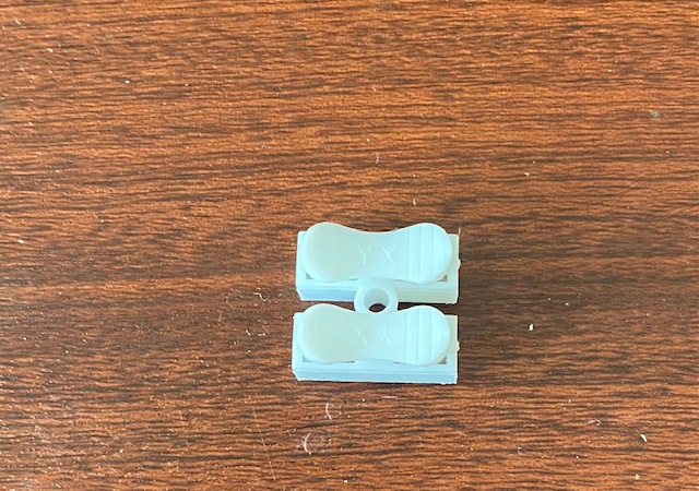
Hi again amberwolf, I will be going to collect this new controller today from Royal Mail, as I was out when it came. But I will test old controller 1st. now those connectors I posted these below are just some connectors I use to test things nothing to do with moped you just press down the top part let go and stick wire in let go and it grips wires tight
https://i.ibb.co/JnJR7wg/IMG-1584.jpg
https://i.ibb.co/qWYgWTH/IMG-1585.jpg
Im going to use those JST-SM plugs for the 5 thin hall wires and join each thin wires with solder and use a heat shrink tube on each 5 wires separately then shrink wrap all 5 as well with 1 wider piece, same as other end of the male or female JST-SM plug. Im still waiting for those to arrive
https://ibb.co/stN0Tm7
Thanks for the web pages etc will be handy.
Im still a bit confused which wire is the ground one when testing the FETs with no power
Also it says green wire and ground etc but those 3 phase wires just go to the controller and other ends to motor but if they are not attached how on earth can they have any readings. As it says green to ground well no way is it going to make a reading
Ive posted a few images of bike wires etc
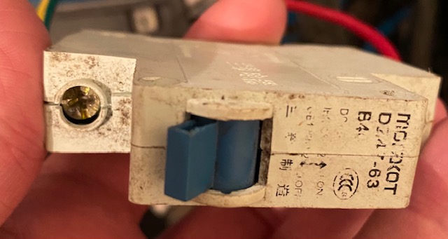
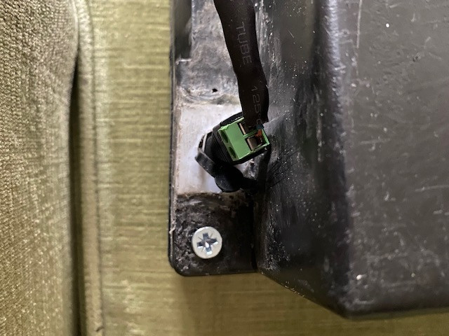
this above is just to disable power to moped when I park it up
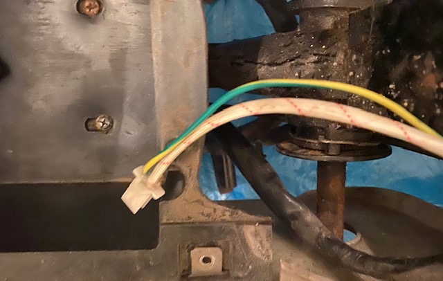
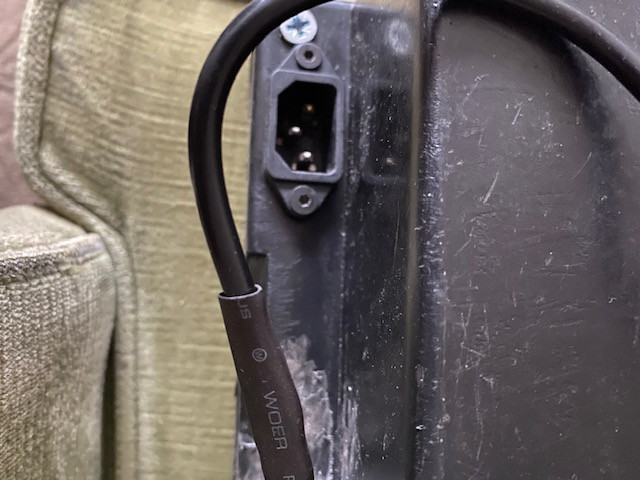
this lead above is plugged into that IRC connector plug just below the front of seat what I mentioned. I asked Erider and they said its a charging port. so they must mean when it had LA batteries
this is a jack plug charging port on battery
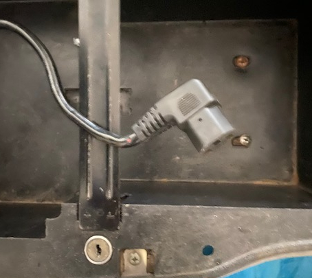
this is the discharge port of batt what that lead plugs into below
Just received new controller today but not sure what leads go where I think I have done it right not tried it on moped yet
on old one it says 350W 25a but this new one is different
Ok now I think this is right wires with red circle must be hall wires as there is 5
the plug in pink circle I don't know where that go its 4 pins
the plugs in yellow circle I think go to the alarm as that's 2 connections
the black mark I think those 2 are to replace 2 plugs what come from controller and go into wiring loom
the light green circle I think is the throttle as 3 wires black red and blue
the dark blue are battery power leads
and the light blue are the 3 phase wires
would this be correct

https://i.ibb.co/JnJR7wg/IMG-1584.jpg
https://i.ibb.co/qWYgWTH/IMG-1585.jpg
The larger blocky white ones are not typically JST; they are usually a variation of Tamiya/Molex that I can never remember the name of.JST-SM are specifically just the black ones like the ones you bought with 5 wires (they come in many pin counts).
Assuming the wire colors used are standard (red = 5v, black = ground, yellow/green/blue = hall signal wires) then if the black wire was loose, then the hall sensors would not work (or would work incorreclty or intermittenly, and could cause exactly the problems you have described (depending on controller design). The black wire is the ground wire for all the sensors. Without that, there is no voltage reference for the controller to compare their output to, and no correct current path for the signals.
Im going to use those JST-SM plugs for the 5 thin hall wires and join each thin wires with solder and use a heat shrink tube on each 5 wires separately then shrink wrap all 5 as well with 1 wider piece, same as other end of the male or female JST-SM plug. Im still waiting for those to arrive
https://ibb.co/stN0Tm7
Thanks for the web pages etc will be handy.
Im still a bit confused which wire is the ground one when testing the FETs with no power
Also it says green wire and ground etc but those 3 phase wires just go to the controller and other ends to motor but if they are not attached how on earth can they have any readings. As it says green to ground well no way is it going to make a reading
Ive posted a few images of bike wires etc
this above is just to disable power to moped when I park it up
this lead above is plugged into that IRC connector plug just below the front of seat what I mentioned. I asked Erider and they said its a charging port. so they must mean when it had LA batteries
this is a jack plug charging port on battery
this is the discharge port of batt what that lead plugs into below
Just received new controller today but not sure what leads go where I think I have done it right not tried it on moped yet
on old one it says 350W 25a but this new one is different
Ok now I think this is right wires with red circle must be hall wires as there is 5
the plug in pink circle I don't know where that go its 4 pins
the plugs in yellow circle I think go to the alarm as that's 2 connections
the black mark I think those 2 are to replace 2 plugs what come from controller and go into wiring loom
the light green circle I think is the throttle as 3 wires black red and blue
the dark blue are battery power leads
and the light blue are the 3 phase wires
would this be correct
Ground is always (unless otherwise specified) the battery (or other power source) negative wire (usually black) of whatever you are testing (whether or not it is connected to that power source). So for the controller, if it is not connected to anything for a test, the ground you connect to for tests requiring ground connection go to the battery negative wire of the controller itself (even though it is not connected to a battery during the test).spudman said:Im still a bit confused which wire is the ground one when testing the FETs with no power
Also it says green wire and ground etc but those 3 phase wires just go to the controller and other ends to motor but if they are not attached how on earth can they have any readings. As it says green to ground well no way is it going to make a reading
You must test the phase wires that are actually on the controller, to test the controller's FETs' resistance. Not to the motor. The only wires you will be testing for a FET test are only on the controller itself, and must be disconnected from the battery and the motor during the test.
Since it is now unused, then if you wanted to build your charger into the bike and then use that for the charger's power cord, as long as it has a full three wire connection (but if it only has two, then it would be safer/easier to replace the connector and cable with a bolt-on extension cable for the charger's wall AC plug.
this lead above is plugged into that IRC connector plug just below the front of seat what I mentioned. I asked Erider and they said its a charging port. so they must mean when it had LA batteries
If you're not building the charger in, then don't worry about it and just leave it as-is, disconnected.
If you do build the charger in, I'd recommend getting a separate new one specifically for that, not using the original, so you have a spare in case something happens to the then-built-in one, because typical chargers aren't sturdy enough to survive typical riding conditions long term. If you go that route, we can talk about chargers that would work.
this is the discharge port of batt what that lead plugs into below
I would never use that type of socket or plug for anything directly to the battery, for a couple reasons. The first is that it is possible to directly accidentally plug that into a cord that goes into the wall, which is likely to destroy the bike and/or the battery.
The second is that it isn't made to carry more than 10-15A, and that's only if it's a good cord; the skinny-wired ones commonly misused like this tend to be only able to handle a few A. Also, the cord you show with the gray end looks like it is nicked with exposed copper just at the base of the plug; I would just completely replace that entire plug and socket and cord with something more appropriate, more matching whatever wire and connector your new battery has installed on it. (or better)
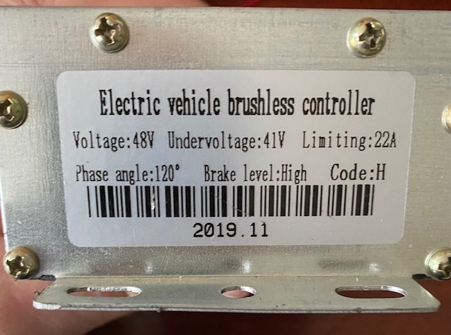
If the "limiting 22A" is the continuous limit (rather than max, and max is about twice the continous for a few seconds), then it is going to be able to supply more than twice the power the original did, so if the motor is put under that much load, it could overheat the motor eventually.Just received new controller today but not sure what leads go where I think I have done it right not tried it on moped yet
on old one it says 350W 25a but this new one is different
If the 22A is both max and continuous, then the same applies.
If that 22A is the max limit, and continous is half that, then it's about the same as the old one, but a little less max power.
No real way to find out without testing. Without a wattmeter or some other way to monitor current, you can't know for sure; you can only go by "feel" of the bike compared to how it felt when it worked with the original. If it feels like it takes off slower or pulls less hard, then the new one is a lower max than the original. If it feels like it accelerates faster, pulls harder, then the new is higher than original. It will probably be about the same, at a guess.
Undervoltage 41v should match or be above your new battery's LVC / undervoltage; should be ok.
Brake level: High means that to use the ebrake you would wire it so the ebrake lever connects that wire to 12v of the controller (or higher, depending on the specific controller instructions; if there aren't any, assume 12v max so you don't damage anything; there may be no 12v coming out of the controller, so you might have to run a wire out of it to do that if you don't have a 12v source on the bike already).
Probably.Ok now I think this is right wires with red circle must be hall wires as there is 5
I don't know what any of those would be; there are several possiblities, and without a wiring diagram from the seller you would need to test them. I highly recommend asking the seller for that specific controller's wiring diagram; most sellers already have this on the webpage it's sold from, but some sell several models on the same page, or don't have a diagram, or don't know which diagram goes with which controller.the plug in pink circle I don't know where that go its 4 pins
the plugs in yellow circle I think go to the alarm as that's 2 connections
the black mark I think those 2 are to replace 2 plugs what come from controller and go into wiring loom
Even if they appear to match color and/or connector of something already on the bike, because the wiring on the bike was modified by previous owner and may not match what erider built it as, so it is possible to damage things by assuming and just connecting them.
Testing them will require first just connecting the controller to the battery, then doing some voltage measurements, and then may require opening the controller to see if they are marked inside.
Probably throttle, could be PAS. (or other things like ebrake, etc) I would test this before hooking your throttle up. If it's for throttle, then a voltmeter red lead will measure about 5v on one wire (usually red) with the meter black lead on the battery negative, when the battery is hooked up correctly to the black and red battery wires, and the orange thin keyswitch/ignition wire is connected to battery positive. (usually red) The other two wires (blue and black) should read about 0v. If those are true, then throttle probably connects with it's red to controller red, black to controller black, and signal (usually white or green) to controller blue.the light green circle I think is the throttle as 3 wires black red and blue
Probably.the dark blue are battery power leads
Probably.and the light blue are the 3 phase wires
The white wire pair is probably self-learn. It stays unconnected normally. If once you connect the phase and hall wires to the motor, the motor does not operate correctly (assuming the motor halls are good, which isn't known yet), then with the motor offground, you would hook up the white wires to each other, the motor should spin (usually slowly) on it's own. If that's the right direction, just turn it off and unplug the wires. If it's the wrong direction, turn it off and wait a minute then back on again and it should rotate the other way, then turn off and unplug white wires. If it doesn't chagne direction, then unplug white wires with system on, then reconnect. Disconnect once it's spinning the right way. If that still doesn't work, you may have to manually go thru the phase/hall wiring order combinations to make it work.
Note that if they provided no diagram, you cannot know for certain what any wire is without testing it; there are no "standards" that everyone follows.
Hi again amberwolf just like to say again many thanks for helping me, its most appreciated, But Im afraid Im still clueless about where to touch multimeter black probe for ground
would this black wire in yellow square which goes to the controller be ground wire as the opposite one in the blue square is the power from battery
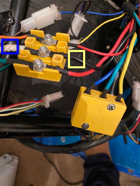
Also what are those yellow connectors called as I have noticed when tightening the nuts they seem loose
I have not tried new controller yet until IM 100% where all the wires go. Yes those 2 white wires are learning wires, as I watched a video on youtube about the white wires
now this below is the plug on moped which I plug into the battery, and in that yellow square it says N = negative right is L =live do you mean stick black meter probe into that and red probe go to green phase wire what go to controller unplugged from those yellow connectors as I tried that and nothing happens on meter
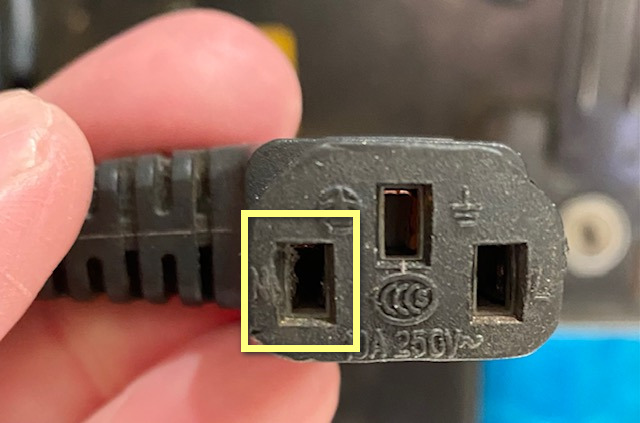
do I have the 5 hall wires connected or disconnected during the test
I had to use that type of plug as that is what's on moped
this is the new battery below when I 1st fitted it in case and as you can see there is a square cut for a IEC plug and the charge end is a jack plug what I glued in

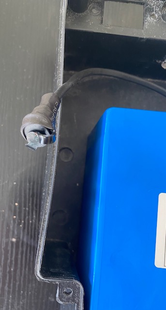
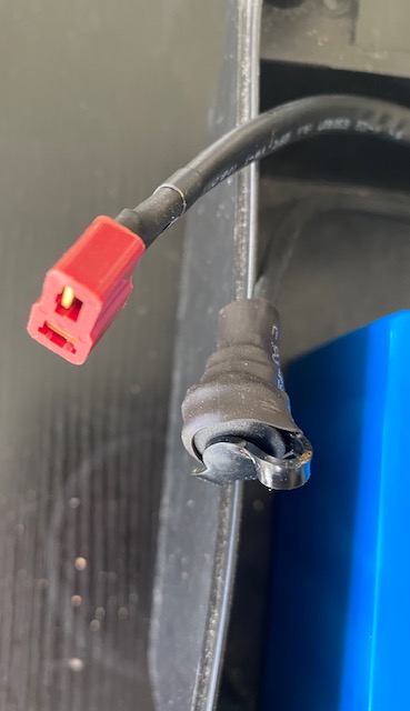

I dont see any cord with a grey end looks like it is nicked with exposed copper just at the base of the plug, can you show me what image its in
I got a reply from ERider regarding the controller diagram
There reply
would this black wire in yellow square which goes to the controller be ground wire as the opposite one in the blue square is the power from battery
Also what are those yellow connectors called as I have noticed when tightening the nuts they seem loose
I have not tried new controller yet until IM 100% where all the wires go. Yes those 2 white wires are learning wires, as I watched a video on youtube about the white wires
now this below is the plug on moped which I plug into the battery, and in that yellow square it says N = negative right is L =live do you mean stick black meter probe into that and red probe go to green phase wire what go to controller unplugged from those yellow connectors as I tried that and nothing happens on meter
do I have the 5 hall wires connected or disconnected during the test
I would never use that type of socket or plug for anything directly to the battery, for a couple reasons. The first is that it is possible to directly accidentally plug that into a cord that goes into the wall, which is likely to destroy the bike and/or the battery.
I had to use that type of plug as that is what's on moped
this is the new battery below when I 1st fitted it in case and as you can see there is a square cut for a IEC plug and the charge end is a jack plug what I glued in
Also, the cord you show with the gray end looks like it is nicked with exposed copper just at the base of the plug; I would just completely replace that entire plug and socket and cord with something more appropriate, more matching whatever wire and connector your new battery has installed on it. (or better)
I dont see any cord with a grey end looks like it is nicked with exposed copper just at the base of the plug, can you show me what image its in
I got a reply from ERider regarding the controller diagram
There reply
. We don't have wiring diagrams for the controller wires. The connectors are mainly all different and should guide you
If that is the controller ground (battery negative) wire, then yes, that's where the meter goes during any tests that need to connnect to controller ground.spudman said:Hi again amberwolf just like to say again many thanks for helping me, its most appreciated, But Im afraid Im still clueless about where to touch multimeter black probe for ground
would this black wire in yellow square which goes to the controller be ground wire as the opposite one in the blue square is the power from battery
If the test is supposed to be done without power (like the FET resistance test), I recommend disconnecting the controller completely from the battery, motor, etc. for the test.
If the test is supposed to be done with power (like the hall test), then leave the controller connected normaly, and just insert the black meter lead probe under the heatshrink until it is held to the metal part of the wire lug, so you don't have to hold it yourself, then tape the meter lead wire to the other wire or whatever else is right there so it wont' fall out during the test, and this frees up your hands for other parts of the test.
They also make alligator clip leads for meters:
https://www.google.com/search?q=alligator+clip+banana+plug+leads&tbm=isch
I don't know what their name is, but a google image search on "hubmotor phase wire connectors" found a bunch of types of connectors, including some that look like them:Also what are those yellow connectors called as I have noticed when tightening the nuts they seem loose
https://www.google.com/search?q=hubmotor+phase+wire+connectors&tbm=isch
I don't know which of the ones that look like that, if any, are any good.
The main reason they usually come loose is that there arent' any locking washer or nut hardware on them, so thermal expansion and vibration loosen the nuts over time. The looser they are, the more heating there is, and the worse the problem gets, and the worse it is the faster it gets worse.
If you use lockwashers, even just split washers like these
https://www.google.com/search?q=split+washers&tbm=isch
then the nuts will stay tight longer/better than with nothing. But you should use regular flat washers between the split washers and the copper/etc wire lugs, or the splitwashers just cut into/crush the lug surface and still loosen up. The flat washers have to be as big as or bigger than the split washers, but smaller than the lug rings, so they don't sit on the wire crimp area, just on the flat ring. The split washers ahve to be smaller than the flat washers or the same size, and the same as the flat ring part of the nut.
Some example of washer use; there are much better ones out there but this one came up in the search above
https://www.wikihow.com/Use-Lock-Washers
The other reason is often there is plastic between the base of the "bolt" and the wire lugs, and the plastic crushes and deforms (and melts from heat), so that leaves space and then the hardware isn't tight anymore. In the pic on this page
https://www.google.com/imgres?imgurl=https%3A%2F%2Fi5.walmartimages.com%2Fasr%2F019ed4f8-ad99-42b1-8a91-15fc8b1f9f05.5f5a992e71e2ab20dabe29370d8a82f5.jpeg&imgrefurl=https%3A%2F%2Fwww.walmart.com%2Fip%2FElectric-Bicycle-E-Bike-Motor-Controller-Wire-Connection-Box-Insulation-Box-Phase-Battery-Wire-Connector
you can see the yellow plastic has flowed over some of the metal base of the bolts on two of the three bolts; that plastic is going to cause loosening of the nuts over time. Removing it before using them would help.
If the bolts and nuts are soft metal (common), they can also distort during tightening and then never hold securely anymore.
Most of the connector stuff used on ebikes, scooters, etc., is the cheapest thing they can get, so it is made of softer more easily damaged materials, poorly designed for the purpose (often it is not actually even made for the purpose it is used for, like those IEC AC connectors being used for battery DC charging and controller plugs!).
now this below is the plug on moped which I plug into the battery, and in that yellow square it says N = negative right is L =live
N is not negative. N is Neutral, because that plug is designed only for AC use on wall plugs, not for batteries and DC. The L is for Line, and the other symbol like an upside down T with two other lines is Ground. Those are all for AC plug wires, not for battery wires. If you look at the bottom edge, it says "10A 250V ~", and that little squiggle means "AC"; there isn't a DC rating on it, indicating it is only made for AC use). So you need to completely ignore any markings that are on that wrongly-used plug, because they have nothing to do with how it is being misused on your bike.
To find out which hole is which on that plug, you'd need to measure continuity from each hole to whatever the wires are connected to on the other end. Set your meter to 20ohms or continuity. Use red lead in first hole, touch black lead to each wire end at the other end of the cable, in turn. The one that shows a reading other than OL, or that beeps, is what is connected to that hole. Do the same for each other hole.
Dont' forget to add this to the complete bike wiring diagram you are drawing up.
(really, if you aren't drawing one up, you really really really should be; it'll make future troubleshooting and modifications easier for you.). I dont' mean for you to use that connector at all for anything, if it is the gray one in your previous picture, with the apparent damage exposing the wire inside. As I said before, I think you should replace that whole cable and plug, as well as the matching one on the battery case, with ones designed for the purpose of battery connections.do you mean stick black meter probe into that and red probe go to green phase wire what go to controller unplugged from those yellow connectors as I tried that and nothing happens on meter
There are no tests where i suggested you connect anything to that plug. (except just now, above, if you want to know which hole is for which wire at the other end of it)
During which test? There are several tests that have been suggested:do I have the 5 hall wires connected or disconnected during the test
Throttle test
Hall test
FET test
The halls need to be connected for any test that uses them to spin the motor, or that is intended to test them.
The FET test should be done with the controller not connected to any other part of the bike.
You can change it, if you want to. You don't have to use it.I would never use that type of socket or plug for anything directly to the battery, for a couple reasons. The first is that it is possible to directly accidentally plug that into a cord that goes into the wall, which is likely to destroy the bike and/or the battery.
I had to use that type of plug as that is what's on moped
If you do use it, just make sure it works right, and keep in mind it is not meant to be used the way it is being used, so when it doesnt' work right, that is one reason why. (for one, it isn't designed to be secure against vibration, so it can wiggle out of the connector, and make bad connections. Bad connections can do all sorts of things, including cause a fire, but they can also cause the bike to act wierd in various ways.
The small red connector you see on the battery's discharge cable is called a Deans. It is a much better plug to use than the IEC AC connector being misused for this now.this is the new battery below when I 1st fitted it in case and as you can see there is a square cut for a IEC plug and the charge end is a jack plug what I glued in
https://www.google.com/search?q=deans+plugs&tbm=isch
If possible I recommend using one of those for the bike end of the battery plug, instead of the misused IEC AC connector. Even though the Deans is much smaller, it is much more secure and capable as a DC connector than the IEC AC is. There are several sizes, you just need to get the matching size. I recommend getting one with wires already soldered to it (12g is probably large enough, 10g if necessary), that are long enough to reach that bolt-together yellow block the battery goes to now, with ring terminals already crimped to them. If you don't find any like that, contact some of the places that sell them with wires on there and see if they are willing to make them the way you need them.
Alternately, you can replace the Deans connector that came on the battery with something else entirely, and also a matching connector and cable on the bike, but just using the existing Deans is simpler. .
The image I had quoted from you, immediately above what you just quoted from meAlso, the cord you show with the gray end looks like it is nicked with exposed copper just at the base of the plug; I would just completely replace that entire plug and socket and cord with something more appropriate, more matching whatever wire and connector your new battery has installed on it. (or better)
I dont see any cord with a grey end looks like it is nicked with exposed copper just at the base of the plug, can you show me what image its in
It looks very gray in that picture. If it is not gray, then the camera or lighting has made it look gray. Perhaps it is actually black? Either way, it is that cord and plug.
This may or may not be the same cord you just showed me in this post, here:
If that is the controller ground (battery negative) wire, then yes, that's where the meter goes during any tests that need to connnect to controller ground.
Well I touched the black probe on that wire then tried the green phase wire 1st. And all phase wires wasn’t connected to controller and I put meter on continuity and nothing happened but I thought continuity was to see if there was a break in a wire so are the green and that black wire supposed to be joined then as can’t see how. I also set meter to diode to but same thing nothing.
I don’t even know if that black wire is ground wire or negative
Are you saying that I need to remove that discharge cable on moped and exchange for a deans connection. As I’m not too sure where the end of that cable goes to obviously the back of moped to those yellow box’s
Or do you mean just cut end off that iec plug on moped and fit a deans plug it would mean modifying the battery slot where I plug into discharge lead now and make that deans plug glued into same position where that IEC plug is now on battery
I still don’t see the image of a grey wire with the apparent damage exposing the wire inside.
I’m lost where that one is
I got a reply from ERider regarding the controller diagram
There reply below
We don't have wiring diagrams for the controller wires. The connectors are mainly all different and should guide you
Which test are you trying to perform?spudman said:If that is the controller ground (battery negative) wire, then yes, that's where the meter goes during any tests that need to connnect to controller ground.
Well I touched the black probe on that wire then tried the green phase wire 1st. And all phase wires wasn’t connected to controller and I put meter on continuity and nothing happened but I thought continuity was to see if there was a break in a wire so are the green and that black wire supposed to be joined then as can’t see how. I also set meter to diode to but same thing nothing.
Hall test?
FET test?
Throttle test?
Some other test?
Can you post the exact steps of the test you are trying to do, as a list, one step at a time?
I would recommend using the test procedures as documented here:
https://ebikes.ca/learn/troubleshooting.html
Depending on the specific test you are doing, there are separate documents for each one.
If you are trying to do the FET test, I would recommend using this one:
https://ebikes.ca/documents/BlownMosfets.pdf
If you are trying to do the hall test, either the one I previously posted, or this one
https://ebikes.ca/documents/HallSensorTestingFinal.pdf
If you are trying to do the throttle test, either the one I previously posted, or this one
https://ebikes.ca/documents/ThrottleTesting.pdf
If it is the thickest black wire coming from the controller box, then if they used normal coloring, it is battery negative (ground). The only way to actually know for sure is to open the controller and trace out where it goes, but that should not be necessary.I don’t even know if that black wire is ground wire or negative
Are you saying that I need to remove that discharge cable on moped and exchange for a deans connection. As I’m not too sure where the end of that cable goes to obviously the back of moped to those yellow box’s
Or do you mean just cut end off that iec plug on moped and fit a deans plug it would mean modifying the battery slot where I plug into discharge lead now and make that deans pl ug glued into same position where that IEC plug is now on battery
It depends on what you want to do. If you prefer to use the IEC plug, you can.
If you want to change it (which I would recommend), I would completely remove the entire IEC-ended cable (as it appears to just be most of a computer / etc powercord), and replace it with a correct-size (to match the existing battery Deans connector) Deans connector that is pre-wired with the right length of wire to reach the point that the IEC cable presently goes to, and has ring terminals preinstalled on it's wires so that you only have to bolt it right on.
If you have to splice a Deans into the original cabling instead, it is not as likely to be as good a connection as if it is already premade and ready to bolt on.
Regarding gluing the plug in, Deans take a fair bit of force to plug and unplug. Glue probably won't hold it in place while you do that. I would use something like this
https://www.spotonrc.com/product-page/deans-connector-bulkhead
to secure it instead. There are others out there, too, if you don't like that one.
https://www.google.com/search?q=deans+connector+mounting+bracket
I linked and showed right there in the previous post, next to my quote of your question about it, along with some information about whether it is gray or black. I don't know any other way to show you. I can only recommend re-reading that section of that post.I still don’t see the image of a grey wire with the apparent damage exposing the wire inside.
I’m lost where that one is
That is one of the least helpful things I have ever heard from a bike seller or manufacturer.I got a reply from ERider regarding the controller diagram
There reply below
We don't have wiring diagrams for the controller wires. The connectors are mainly all different and should guide you
Unfortunately that means you would have to guess at what connector is which, based on the info you've already posted about it and perhaps what I posted (since I dont' have a way to know for sure).
There are certain tests that can be done to verify some of them, without opening the controller. When we get that far, I can type them up.
Hi again amberwolf I do hope you realise all this help from you is most appreciated as I wont be able to sort moped without your help
its the FET test btw do I also remove the 5 hall sensor wires from controller when Im doing the Phase wires test FETs
ok I have taken images of my 2 meters I have here is this one below the correct setting for testing the phase wires FET test
as it says on the blown FET test page Switch the multimeter to continuity (diode) mode or 200 ohm mode.
that's 3 modes isn't it or maybe I'm wrong continuity, diode, & 200 ohm mode
first meter
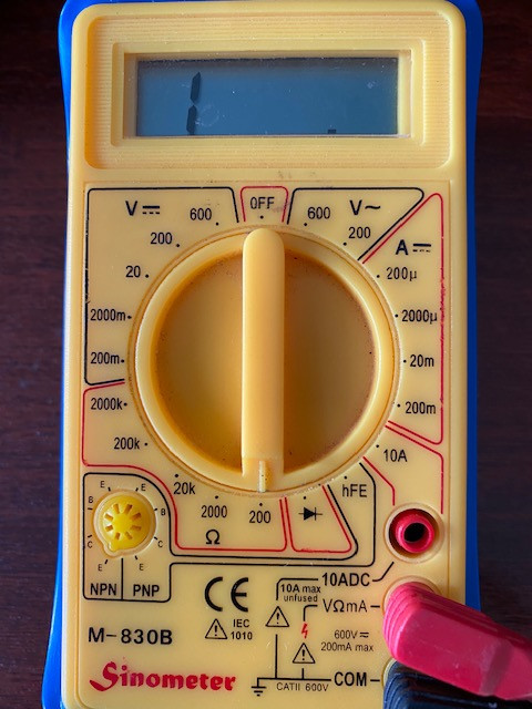
2nd meter
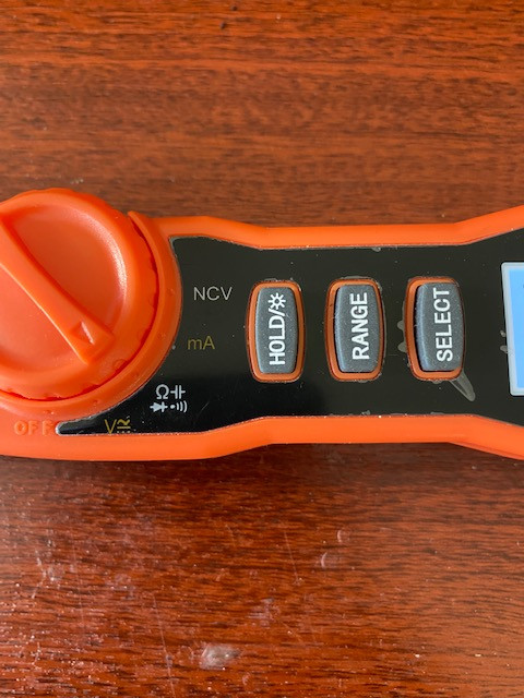
2nd meter

2nd meter
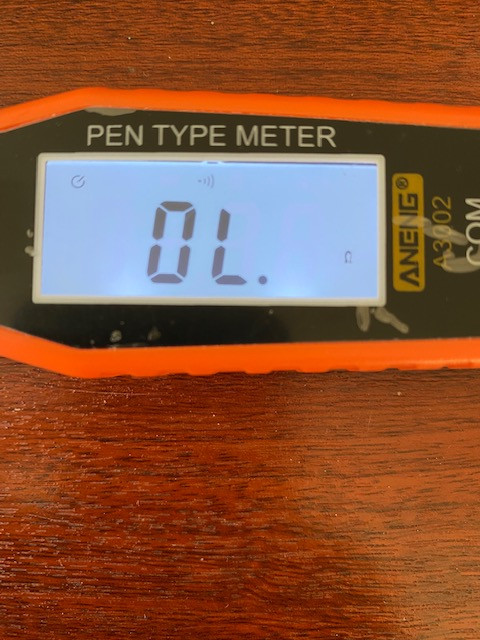
And I believe this is that cable where you said about grey and exposed cable inside god u must have eyes like a hawk as I never saw that I will later change that plug.
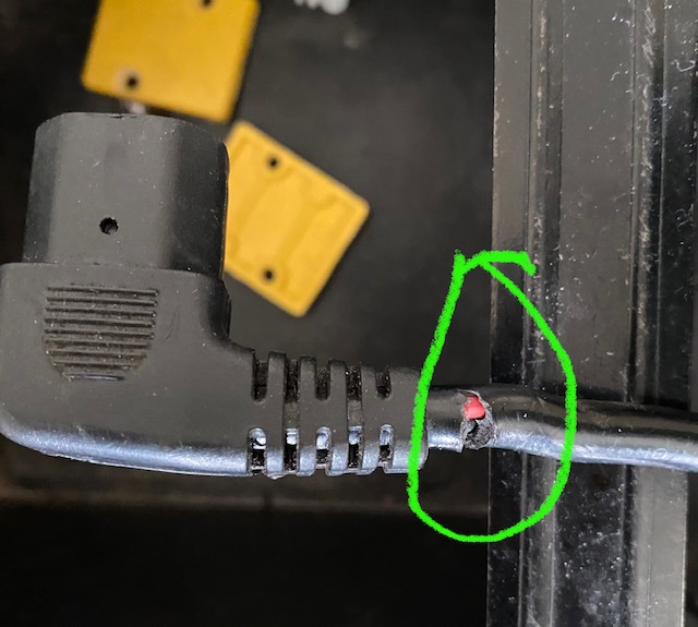
Yes I will try to find a complete deans cable with a ring connection at other end to go to those yellow box connectors. I will have to turn moped upside down to check wiring loom to pull out old IEC cable then fit deans one, But thats later once I get moped running then I will do all that. I have some real black sticky tape to hide new deans cable in wiring loom later
Ive looked on Ebay and also Amazon for this deans connector https://www.spotonrc.com/product-page/deans-connector-bulkhead
But cant find it anywhere Im in the UK btw
It’s ok as I have now ordered it from that web site you gave me as I’m in no hurry for it. With shipping cost it’s only £8.41.
I’m going to try the new controller tomorrow, as getting fed up now waiting to get moped working. I have checked all the wires and I know where phase and hall wires go. Plus see alarm 2 connectors also throttle. There is 2 single leads with bullit connectors so think they go to display and horn, indicator and headlamp switch
Hi Well tried new controller today Friday. made sure everything was secure, and nothing happened at all so it looks like either a wire is broke between hall or phase wires to back wheel or a loose wire inside the wheel, so when you come back I will have removed the wheel hopefully by then and can show you more details on the wires where in axle they are and maybe you can advise me how to remove casing on wheel to access the wires, probably will need a new hall and phase wire cable plus I'm going to have to change that power cord to battery discharge it will be a deans male connector I believe. also will it be long enough to reach from battery compartment to back of moped to those yellow block connectors and will it have a ring at end I may as well sort that too while moped is upside down
This is the crankcase side of wheel below also a few Allen nuts around case too
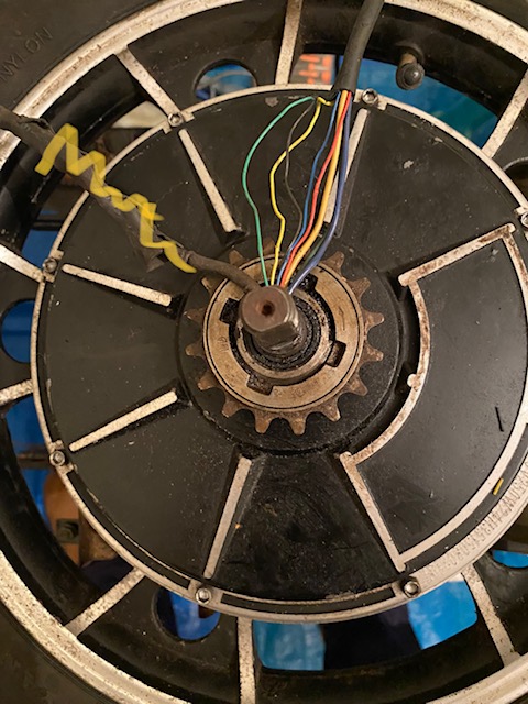
Well I have managed to remove opposite side to crankcase it came off so easy when I banged it on concrete, but cant get the motor out of the rim part I removed Allen nuts on crankcase side but think I will need a gear puller for that not 100% if I am right. I have ordered one as they not expensive. Just waiting now for your help on the sensors
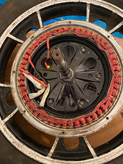
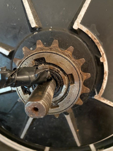
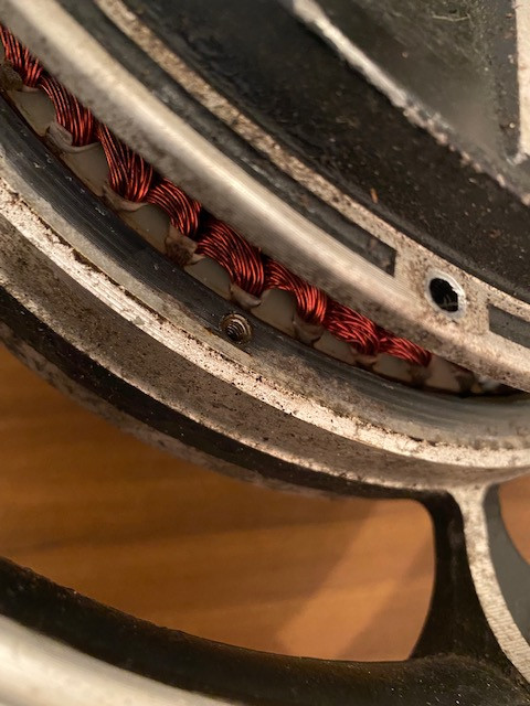
I would like to remove this old drum as I would like to fit new drum which came with brakes But will it come off by banging those cut outs on outside as its on a thread
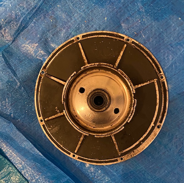
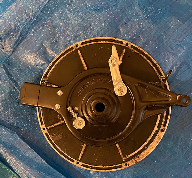
Which test are you trying to perform?
its the FET test btw do I also remove the 5 hall sensor wires from controller when Im doing the Phase wires test FETs
ok I have taken images of my 2 meters I have here is this one below the correct setting for testing the phase wires FET test
as it says on the blown FET test page Switch the multimeter to continuity (diode) mode or 200 ohm mode.
that's 3 modes isn't it or maybe I'm wrong continuity, diode, & 200 ohm mode
first meter
2nd meter
2nd meter
2nd meter
And I believe this is that cable where you said about grey and exposed cable inside god u must have eyes like a hawk as I never saw that I will later change that plug.
If you want to change it (which I would recommend), I would completely remove the entire IEC-ended cable (as it appears to just be most of a computer / etc powercord), and replace it with a correct-size (to match the existing battery Deans connector) Deans connector that is pre-wired with the right length of wire to reach the point that the IEC cable presently goes to, and has ring terminals preinstalled on it's wires so that you only have to bolt it right on.
Yes I will try to find a complete deans cable with a ring connection at other end to go to those yellow box connectors. I will have to turn moped upside down to check wiring loom to pull out old IEC cable then fit deans one, But thats later once I get moped running then I will do all that. I have some real black sticky tape to hide new deans cable in wiring loom later
Ive looked on Ebay and also Amazon for this deans connector https://www.spotonrc.com/product-page/deans-connector-bulkhead
But cant find it anywhere Im in the UK btw
It’s ok as I have now ordered it from that web site you gave me as I’m in no hurry for it. With shipping cost it’s only £8.41.
I’m going to try the new controller tomorrow, as getting fed up now waiting to get moped working. I have checked all the wires and I know where phase and hall wires go. Plus see alarm 2 connectors also throttle. There is 2 single leads with bullit connectors so think they go to display and horn, indicator and headlamp switch
Hi Well tried new controller today Friday. made sure everything was secure, and nothing happened at all so it looks like either a wire is broke between hall or phase wires to back wheel or a loose wire inside the wheel, so when you come back I will have removed the wheel hopefully by then and can show you more details on the wires where in axle they are and maybe you can advise me how to remove casing on wheel to access the wires, probably will need a new hall and phase wire cable plus I'm going to have to change that power cord to battery discharge it will be a deans male connector I believe. also will it be long enough to reach from battery compartment to back of moped to those yellow block connectors and will it have a ring at end I may as well sort that too while moped is upside down
This is the crankcase side of wheel below also a few Allen nuts around case too
Well I have managed to remove opposite side to crankcase it came off so easy when I banged it on concrete, but cant get the motor out of the rim part I removed Allen nuts on crankcase side but think I will need a gear puller for that not 100% if I am right. I have ordered one as they not expensive. Just waiting now for your help on the sensors
I would like to remove this old drum as I would like to fit new drum which came with brakes But will it come off by banging those cut outs on outside as its on a thread
As noted before, you disconnect teh controller from *everything* for the FET test.spudman said:its the FET test btw do I also remove the 5 hall sensor wires from controller when Im doing the Phase wires test FETs
ok I have taken images of my 2 meters I have here is this one below the correct setting for testing the phase wires FET test
as it says on the blown FET test page Switch the multimeter to continuity (diode) mode or 200 ohm mode.
Note that while the instructions say to set a meter to 200ohm mode, the displays shown on the meter for the readings show almost kohms, which means the meter they are using is not set to that (it is probalby set to auto-range, or to 20kohm mode). In actual 200ohm mode, for those readings, your meter will display OL or whatever it's manual says that it displays when the reading is higher than the selected mode can display. (for instance, some of them show the 1.(blank) that the Victor meter used in the test document does).
Depends on the meter. You must check the manual for your specific meter to verify what modes it has and how they work. Most use diode and continuity as the same mode; the 200ohm mode is separate. You only use one mode for the test as directed by the test document, pick whichever you prefer if it gives a choice, and follow those specific test directions.that's 3 modes isn't it or maybe I'm wrong continuity, diode, & 200 ohm mode
For this meter, the diode / continuity mode is the little arrow symbol next to the 200ohm mode that you have it set to. Either mode should work.first meter
For this meter, you'll need to check its manual for how to select which mode you are using, as it has several modes in that same knob setting; I've never used a meter like that one so you must verify it in it's manual how to do that.2nd meter
Yes, that's the one. AFAICT this is the battery-to-controller power cable, and if so it is entire cable you would be changing out with the Deans plug and cable with ring terminals to go to the yellow bolt-on battery terminal block.And I believe this is that cable where you said about grey and exposed cable inside god u must have eyes like a hawk as I never saw that I will later change that plug.
The good news is the exposed wires I see in your new picture don't show any exposed conductors, so there is little risk of damage/shorting at the moment.
Yes I will try to find a complete deans cable with a ring connection at other end to go to those yellow box connectors. I will have to turn moped upside down to check wiring loom to pull out old IEC cable then fit deans one, But thats later once I get moped running then I will do all that. I have some real black sticky tape to hide new deans cable in wiring loom later
I dont' recommend using tape to tie cables together, the tape just leaves a mess on the wires and comes off when it gets hot. Zip ties are a much better choice when tidying up and securing wiring harnesses, just don't tighten them too much or you can damage wiring. Just enough to hold them together.
Regarding buying the parts, you'll probalby have to have someone make you the right deans connector pre-soldered to a cable of the right lenght and right wire gauge with teh right size ring terminals, etc. Since you probably wont' need more than the one, I don't recommend doing it yourself as you will need to buy tools to crimp, solder, etc., and learn how to do it right to make good connections, which may damage / destroy connections until you get it down.
If you intend to do repairs like this again, or need to do more connections (like ring terminals for the new controller's phase wires, etc), then buying the crimper tool and good crimp-on ring terminals and such, then looking up good tutorials on crimping, etc., and practicing on scrap stuff, would be a good investment of money and time. If crimping or soldering isn't done right, it can make things work very poorly, if at all.
Unless you are certain about which wires do what on the controller, and which are required to make it operate correctly, you can't make any assumptions about what might be causing the new controller to not work. You must first verify that the wiring is correct. If it is not, and any low-voltage wires on the controller are hooked up to voltage that is too high, etc., you may just be blowing up the new controller, or causing it to not work by not hooking things up that have to be, or hooking them up to things they shouldn't be.I’m going to try the new controller tomorrow, as getting fed up now waiting to get moped working. I have checked all the wires and I know where phase and hall wires go. Plus see alarm 2 connectors also throttle. There is 2 single leads with bullit connectors so think they go to display and horn, indicator and headlamp switch
Hi Well tried new controller today Friday. made sure everything was secure, and nothing happened at all so it looks like either a wire is broke between hall or phase wires to back wheel or a loose wire inside the wheel,
To verify the controller wiring, you also have to know what the wiring of the bike itself is.
If you are not willing to have the patience to take the time to test all these things, it's going to be tough for anyone to really help you fix the bike.
If you need it working sooner with less effort, you'll need to buy a controller that has a known-good wiring diagram for it, that has the right current limit and voltage range for your battery and motor, and the right connections for the wires on your bike that went to the old controller. My guess is there isn't one out there that is exactly what you need, but you can still take time (probably a lot) to look at all the many controllers out there and find a matching one from a trustworthy seller.
Or you can save some time and ask known-good sellers like Grin tech at http://ebikes.ca which one they have that will work on your bike. (keeping in mind that many places are shorthanded these days and can take days to weeks to answer questions). They'll cost more, but as long as you provide them with all the right information about your bike and wiring and such, you can be more certain that what they say will work should actually work and be reasonably easy to connect.
Connectors still wont' match, unless you ask/pay them to match the connectors and wiring you already have (which you would need to determine first, by drawing up the diagram for your bike, which if you havent' already done, you still really should do, and post here for reference so we can be more sure of helping you correctly, instead of us just guessing at things).
AFAICR you still haven't done the testing needed to determine that. Until you do, we can't tell you what is needed.so when you come back I will have removed the wheel hopefully by then and can show you more details on the wires where in axle they are and maybe you can advise me how to remove casing on wheel to access the wires, probably will need a new hall and phase wire cable
If you won't take the time to do the tests, and post your step by step results, it's not useful for us to advise you which tests to do or how to do them, and we can't really be much help in fixing your bike.
As I have already said in other posts, you have to choose to get one that is made the right length with the right wires with the right ring terminals already on it. Asking me if it will be long enough/etc wont' help you--you have to do this with the people selling the parts.plus I'm going to have to change that power cord to battery discharge it will be a deans male connector I believe. also will it be long enough to reach from battery compartment to back of moped to those yellow block connectors and will it have a ring at end I may as well sort that too while moped is upside down
Since the gear puller pushes the motor out the opposite side, you'll need to use it on the side with the freewheel.Well I have managed to remove opposite side to crankcase it came off so easy when I banged it on concrete, but cant get the motor out of the rim part I removed Allen nuts on crankcase side but think I will need a gear puller for that not 100% if I am right. I have ordered one as they not expensive.
The reason it is hard to get out is mostly the force of the magnets pulling against the steel inside, and partly because of the motor wires. The extra cable that was added to the motor doesn't help. Be careful when removing it as there is risk of damaging the motor wires (if they aren't already). If you have to you can replace the motor cable (hall and phase wires); if so I'd just get one premade with the right connectors at the non-motor end, long enough to reach the motor from wherever the other end goes on the bike.
The wiring shown there looks like it has been altered, probably to connect that addon cable. It looks like they took some of the windings and diverted them from the original phase wires (which will connect under the white tube coverings), using the red and black heatshrink/etc. There is at least one place where the windings they altered could be shorting to the motor structure, where the copper winding passes thru the hole between two sections of red heatshrink and goes to that yellow (ziptie?). If vibration has worn thru the thin coating on the winding wire, it could short intermittently to the metal motor support there. You can insulate the support and the winding with layers of electrical tape, as long as you ensure it can't come off (or else it could jam up the motor while riding if it gets into the spinning part of the motor).Just waiting now for your help on the sensors
But without knowing what they actually did, or seeing the stuff on the other side, it's hard to say what you will need to do to put it back the way it was. (or if it is necessary to do so).
We can't see the sensors, as those are on the other side, but to test them you still need to do the hall sensor test previously discussed, whcih will require you to reassemble the motor and put it back on the bike so you can use your hand to spin the wheel.
I've never removed one like that. Presumably it will need to come off in the same direction that the motor would be spinning on that side. If that is the left side, then that would be counterclockwise. It's probably VERY tight from braking forces over it's lifetime, so it probably won't come off without the right tool. A bike shop or scooter shop may have the tool, and be able to remove it for you.I would like to remove this old drum as I would like to fit new drum which came with brakes But will it come off by banging those cut outs on outside as its on a thread
If you try just banging on it youll almsot certainly destroy the drum and you could break the motor cover (they're not typically made very well or strong), and have to replace the motor and wheel with a new one. If you don't break the cover but can't get the now-damaged drum off, you won't have a brake on that wheel anymore.
Hi again amberwolf I must admit I was getting a bit worried as didnt think you was coming back, but silly me dont realise we are not always online, have other jobs to do as well
anyway, I have been a bit silly by jumping ahead, I will of course now replace wheel and do those hall tests again. as I have also now ordered crocodile test leads for meters as it was so dam awkward, trying to hold probes with just a point.
I don't know if Erider could supply that cable I doubt it very much, as they didn't seem very helpful on other things. But will ask them, but I dont know who else would make me a cable like that. it has to be male deans plug I believe, and you say a ring terminal other end. I dont know as of yet where that old IEC cable go but will have to cut along wiring loom under the moped Ive pulled the IEC plug and lead through underneath.
is it not possible to look on ebay or amazon for that type of lead, but I dont know what to search for
Yes I have bought some cable ties and wont use tape
I do apologise about this and no I have changed my mind about wanting moped sooner, as its way too cold to ride about on it this weather. I'm not a young person. I already have spent 85 GBP $115.48 I think in us money on a new controller so I don't really want to spend more.
You say here about drawing up a diagram of your bike, do you mean wiring diagram, as Im no good at all that wont know where to start. I know the power cable goes to those yellow junction box, and I think maybe another to where I said below the seat is another IEC male socket. and when I asked Erider they said its a charging port. so I think it was when moped was new, and had 4 x SLA batteries.
this is where you mean when you say

Yes I have some amalgamating rubber tape I can wrap over that bare copper
Yes after I have insulated that bare copper wire I will put side case on wheel tighten up the allen nuts and place wheel back on bike. maybe what you said about that copper wire showing was causing mope not to work, as I know when my nephew was at mine I had throttle fully open and he just kicked back wheel and it spun ok then, But not sure if that is what caused it.
I will do the tests better when my crocodile meter leads arrive.
I wont know what tool to use on that drum, I did ask Erider and of course they was not very helpful all they said was no need to remove that to fit back brakes. But new back brakes came with a new drum. so may just leave that as I dont know how to remove it, and dont want to mess up anything else.
Anyway amberwolf Im so glad you have come back, as I must admit I was stuck knowing what else I could do. so as I keep saying I do appreciate all your help.
I will get wheel replaced on moped and do tests again.
Ok I have fitted wheel back and I 1st checked the 3 phase wires with them not being connected to controller no power
had the meter on diode mode and it showed 1 on screen tried black ground to green numbers started flashing on screen then went back to 1 again. same thing again with power on so maybe its the phase wires are faulty
hall sensor tests was with meter on DC 20V
I then did the hall sensor wire tests, red hall wire to black hall wire = 4.20V
black to yellow = 0.01v
black to blue = 0.01v
black to green = 4.96v
then I did hall wires again by slowly turning wheel backwards wires said 0 to 5v
black to yellow
black to blue ========= all registered between 0 to 5v etc
black to green
this was on my old controller I tested not new one. I also connected up throttle a thumb one mind you but still 3 coloured wires and on the display I could see movement up to say 13 on speedo probably 13 km/h
I have also taped up that copper wire you said about inside wheel where you pointed out. so until I get that flywheel tool arrive I cant take of of side of wheel to see wires
this is the tool I have ordered from ebay https://www.ebay.co.uk/itm/363142327125
hope its the correct one to undo this nut below

as I have also ordered this gear puller but I don't think that's what I need
https://www.ebay.co.uk/itm/221915441955
I was watching this video on youtube https://www.youtube.com/watch?v=SttmrsIjiJc&t=313s
and has he made a mistake at 5.27 into the video as he says on the phase wires he has blue to blue, green to yellow, and yellow to green surely that's wrong as mine isn't like that
Another thing I noticed where those wires go into wheel. well something made me think. if there is 3 phase wires plus 5 hall wires thats 8 wires plus that add on cable has 3 think wires too. so you mean to say there is 6 thick wires and 5 thin wires all going into that grove part in axle as it dont seem to be I will know once i have taken flywheel off as seem strange to me
anyway, I have been a bit silly by jumping ahead, I will of course now replace wheel and do those hall tests again. as I have also now ordered crocodile test leads for meters as it was so dam awkward, trying to hold probes with just a point.
Yes, that's the one. AFAICT this is the battery-to-controller power cable, and if so it is entire cable you would be changing out with the Deans plug and cable with ring terminals to go to the yellow bolt-on battery terminal block.
I don't know if Erider could supply that cable I doubt it very much, as they didn't seem very helpful on other things. But will ask them, but I dont know who else would make me a cable like that. it has to be male deans plug I believe, and you say a ring terminal other end. I dont know as of yet where that old IEC cable go but will have to cut along wiring loom under the moped Ive pulled the IEC plug and lead through underneath.
is it not possible to look on ebay or amazon for that type of lead, but I dont know what to search for
dont' recommend using tape to tie cables together, the tape just leaves a mess on the wires and comes off when it gets hot. Zip ties are a much better choice when tidying up and securing wiring harnesses, just don't tighten them too much or you can damage wiring. Just enough to hold them together.
Yes I have bought some cable ties and wont use tape
To verify the controller wiring, you also have to know what the wiring of the bike itself is.
If you are not willing to have the patience to take the time to test all these things, it's going to be tough for anyone to really help you fix the bike.
If you need it working sooner with less effort, you'll need to buy a controller that has a known-good wiring diagram for it, that has the right current limit and voltage range for your battery and motor, and the right connections for the wires on your bike that went to the old controller. My guess is there isn't one out there that is exactly what you need, but you can still take time (probably a lot) to look at all the many controllers out there and find a matching one from a trustworthy seller.
I do apologise about this and no I have changed my mind about wanting moped sooner, as its way too cold to ride about on it this weather. I'm not a young person. I already have spent 85 GBP $115.48 I think in us money on a new controller so I don't really want to spend more.
Connectors still wont' match, unless you ask/pay them to match the connectors and wiring you already have (which you would need to determine first, by drawing up the diagram for your bike, which if you havent' already done, you still really should do, and post here for reference so we can be more sure of helping you correctly, instead of us just guessing at things).
You say here about drawing up a diagram of your bike, do you mean wiring diagram, as Im no good at all that wont know where to start. I know the power cable goes to those yellow junction box, and I think maybe another to where I said below the seat is another IEC male socket. and when I asked Erider they said its a charging port. so I think it was when moped was new, and had 4 x SLA batteries.
The wiring shown there looks like it has been altered, probably to connect that addon cable. It looks like they took some of the windings and diverted them from the original phase wires (which will connect under the white tube coverings), using the red and black heatshrink/etc. There is at least one place where the windings they altered could be shorting to the motor structure, where the copper winding passes thru the hole between two sections of red heatshrink and goes to that yellow (ziptie?). If vibration has worn thru the thin coating on the winding wire, it could short intermittently to the metal motor support there. You can insulate the support and the winding with layers of electrical tape, as long as you ensure it can't come off (or else it could jam up the motor while riding if it gets into the spinning part of the motor).
But without knowing what they actually did, or seeing the stuff on the other side, it's hard to say what you will need to do to put it back the way it was. (or if it is necessary to do so).
We can't see the sensors, as those are on the other side, but to test them you still need to do the hall sensor test previously discussed, whcih will require you to reassemble the motor and put it back on the bike so you can use your hand to spin the wheel.
this is where you mean when you say
where the copper winding passes thru the hole between two sections of red heatshrink and goes to that yellow (ziptie?)
Yes I have some amalgamating rubber tape I can wrap over that bare copper
We can't see the sensors, as those are on the other side, but to test them you still need to do the hall sensor test previously discussed, whcih will require you to reassemble the motor and put it back on the bike so you can use your hand to spin the wheel.
Yes after I have insulated that bare copper wire I will put side case on wheel tighten up the allen nuts and place wheel back on bike. maybe what you said about that copper wire showing was causing mope not to work, as I know when my nephew was at mine I had throttle fully open and he just kicked back wheel and it spun ok then, But not sure if that is what caused it.
I will do the tests better when my crocodile meter leads arrive.
I've never removed one like that. Presumably it will need to come off in the same direction that the motor would be spinning on that side. If that is the left side, then that would be counterclockwise. It's probably VERY tight from braking forces over it's lifetime, so it probably won't come off without the right tool. A bike shop or scooter shop may have the tool, and be able to remove it for you.
If you try just banging on it youll almsot certainly destroy the drum and you could break the motor cover (they're not typically made very well or strong), and have to replace the motor and wheel with a new one. If you don't break the cover but can't get the now-damaged drum off, you won't have a brake on that wheel anymore.
I wont know what tool to use on that drum, I did ask Erider and of course they was not very helpful all they said was no need to remove that to fit back brakes. But new back brakes came with a new drum. so may just leave that as I dont know how to remove it, and dont want to mess up anything else.
Anyway amberwolf Im so glad you have come back, as I must admit I was stuck knowing what else I could do. so as I keep saying I do appreciate all your help.
I will get wheel replaced on moped and do tests again.
Ok I have fitted wheel back and I 1st checked the 3 phase wires with them not being connected to controller no power
had the meter on diode mode and it showed 1 on screen tried black ground to green numbers started flashing on screen then went back to 1 again. same thing again with power on so maybe its the phase wires are faulty
hall sensor tests was with meter on DC 20V
I then did the hall sensor wire tests, red hall wire to black hall wire = 4.20V
black to yellow = 0.01v
black to blue = 0.01v
black to green = 4.96v
then I did hall wires again by slowly turning wheel backwards wires said 0 to 5v
black to yellow
black to blue ========= all registered between 0 to 5v etc
black to green
this was on my old controller I tested not new one. I also connected up throttle a thumb one mind you but still 3 coloured wires and on the display I could see movement up to say 13 on speedo probably 13 km/h
I have also taped up that copper wire you said about inside wheel where you pointed out. so until I get that flywheel tool arrive I cant take of of side of wheel to see wires
this is the tool I have ordered from ebay https://www.ebay.co.uk/itm/363142327125
hope its the correct one to undo this nut below
as I have also ordered this gear puller but I don't think that's what I need
https://www.ebay.co.uk/itm/221915441955
I was watching this video on youtube https://www.youtube.com/watch?v=SttmrsIjiJc&t=313s
and has he made a mistake at 5.27 into the video as he says on the phase wires he has blue to blue, green to yellow, and yellow to green surely that's wrong as mine isn't like that
Another thing I noticed where those wires go into wheel. well something made me think. if there is 3 phase wires plus 5 hall wires thats 8 wires plus that add on cable has 3 think wires too. so you mean to say there is 6 thick wires and 5 thin wires all going into that grove part in axle as it dont seem to be I will know once i have taken flywheel off as seem strange to me
As I already said, you ask the places that sell the deans connectors and wires, especially if they already say they custom make cables. The RC places (like the one that makes that panel mount holder) are the most likel.spudman said:I don't know if Erider could supply that cable I doubt it very much, as they didn't seem very helpful on other things. But will ask them, but I dont know who else would make me a cable like that. it has to be male deans plug I believe, and you say a ring terminal other end.
Erider probably doesn't even know what a deans is, and almsot certainly doesnt' make anything at all, but simply orders things from a factory in China, who slaps Erider's label on them, and dropships them to whoever orders them. They probably never even see anything themselves, which is why they know nothing about anything and cant' help anyone.
That sounds like a lot of money for such a low power basic controller. Since Erider doesnt' even know that this one works on your bike or how to connect it, I would bet there are probably cheaper places to get the same thing (or equivalent); I don't know any specific ones, but there's a lot of options out there (and many of them would supply at least a basic wiring diagram, even if the labels were badly translated to english). That isnt' really useful to you at this moment, but if you find this controller doesn't work for whatever reason, it gives you a way to start looking for something possibly a tiny bit easier to hook up and use.I do apologise about this and no I have changed my mind about wanting moped sooner, as its way too cold to ride about on it this weather. I'm not a young person. I already have spent 85 GBP $115.48 I think in us money on a new controller so I don't really want to spend more.
One way to do this is to look up "electric moped wiring diagrams" in a google image search, like this:You say here about drawing up a diagram of your bike, do you mean wiring diagram, as Im no good at all that wont know where to start.
https://www.google.com/search?q=%22electric+moped+wiring+diagrams%22&tbm=isch
to get an idea of what kind of information you will need, and different ways to lay it out on paper so that you can follow it.
You could even find one that has the same things on it that you do on your bike, or close enough, then print that out (or copy it off the screen to your own paper), and then cross out the parts you don't have if there are any, and then just mark the wires as you trace them out on the wires with teh masking tape and on the diagram with matching numbers or labels. If you find wires on the diagram that don't go where yours do, cross out the wires it shows and draw your own in. When you have traced every wire on the bike and marked it, then you can use that diagram to redraw it cleanly on your own paper to have for yourself, and/or to help others help you, to figure out problems as they come up later.
If you want to just do it from scratch (probably the best way, but that depends on how you do things, since everyone is different), take a piece of paper (you'll probably need several, or a big poster board, until you get it all down), and a pencil or pen, or even better a set of colored pencils or markers, and draw boxes or circles or whatever shapes you want to represent the parts of your bike. (motor, throttle, brake levers, controller, lights, battery, bolt-on-terminal blocks, etc etc.)
YOu can even draw it out as a shape like the bike itself, so it is all phsyically laid out like the bike is, which makes it a lot easier to follow later (unlike the diagrams that come up in the search I linked above).
(if you know how to do this in the computer with a program, you can do it that way instead if you like; otherwise paper and pen/pencil is an easy enough way to do it)
Then you can trace out where each cable goes on the bike, from one part to another, and mark each wire end as you trace it out with masking tape, etc., with a number on it that you also write on the diagram. That way you know which ones youv'e traced, and can tell where on teh diagram they go.
For wires you can't physically see or feel from one end to the other, you can use your multimeter on continuity or 200ohms mode to test where wires go, by putting the red lead on one end of the wire you are looking for the other end of, and touching it to the ends of wires you think it might be, until you get a low ohms reading that isn't OL or whatever your meter uses to tell you no connection. (BTW, doing the tracing with a meter will also test each wire for continuity, so in the unlikely event there are any broken ones you'll find them this way).
As you test each wire, you mark it on the wire as noted above, and draw it in the wiring diagram you are drawing up.
The nice thing about drawing it all up as you go, then whenever you are fixing or changing something now or in the future, you can simply refer to the diagram. You can even attach it to a post in this thread so you can't lose it, so later you can come back and refer to it if you have problems and don't have your original. Others can also see this and then help you more easily with troubleshooting problems if you have any later, and possibly even themselves if they have a bike like yours that they need a wiring diagram for.
Yes, that is what we guessed in previous posts here when you asked about it.I know the power cable goes to those yellow junction box, and I think maybe another to where I said below the seat is another IEC male socket. and when I asked Erider they said its a charging port. so I think it was when moped was new, and had 4 x SLA batteries.
Yep, that's the spot. It may not be a problem, or ever become one, but since you already have it open, it's safer to make sure while you're there.this is where you mean when you saywhere the copper winding passes thru the hole between two sections of red heatshrink and goes to that yellow (ziptie?)
Yes I have some amalgamating rubber tape I can wrap over that bare copper
I would guess that is not the cause, as usually a short to windings would just blow up the controller FETs on that phase. If it doesn't, it can cause the controller to shutdown, either momentarily (causing a jerky feeling while riding) or completely (requiring you to stop, turn the bike off, and back on, to reset it).maybe what you said about that copper wire showing was causing mope not to work, as I know when my nephew was at mine I had throttle fully open and he just kicked back wheel and it spun ok then, But not sure if that is what caused it.
As I said before, you should talk to your local bike or scooter shops that fix these things, as those places would have tools to do these things. Most such places will be able to just let you bring in the wheel with the part you need removed or changed out, and use their tools to do so. Typically they dont' charge much, and it is often less than the tools you'd need would cost.I wont know what tool to use on that drum, I did ask Erider and of course they was not very helpful all they said was no need to remove that to fit back brakes. But new back brakes came with a new drum. so may just leave that as I dont know how to remove it, and dont want to mess up anything else.
FWIW, google shows that is often called a Band Brake, rather than a Drum Brake, if it helps you locate information about them. I don't know specifically which tool that one uses, and tried a bunch of different searches on google to find one, but couldn't.
BTW, I don't really think I would trust any instructions Erider could provide, even if they would help. If you look at this document
https://eriderbikes.com/wp-content/uploads/2018/11/USER-MANUAL-AND-ASSEMBLY-INSTRUCTIONS-MODEL-18-4.pdf
you'll find a section near the end that says "Do not be concerned that you are left with surplus screws and/or bolts."; when they have no way of verifying that the end-user has followed all the instructions for assembly correctly, and there could well be major required parts left over that could cause vehicle failure while riding.
Ok I have fitted wheel back and I 1st checked the 3 phase wires with them not being connected to controller no power
had the meter on diode mode and it showed 1 on screen tried black ground to green numbers started flashing on screen then went back to 1 again. same thing again with power on so maybe its the phase wires are faulty
I can't follow the results you have given as there is not nearly enough information to know what you are testing or what results you got, so I can't tell you anything about what they might mean.
It sounds like you were testing the phase wires of the motor itself, comparing them to the battery negative, first without power and then with power. I don't know of any test like that that needs to be done, based on what we've talked about so far. If you are doing some other test, there isnt' enough info to tell which one or how it was being done or what the results are.
Please post a numbered list of the exact steps you are doing to perform the test, as you do them, with the exact results of each test, so we can see what test you are doing, and if you are doing the test steps that need to be done, and if the results you are getting match what you should get for the steps you are actually doing.
This sounds like correct results for working hall sensors and working wiring from the controller to the motor. So you can mark those as tested and working, unless we find some other problem later.hall sensor tests was with meter on DC 20V
I then did the hall sensor wire tests, red hall wire to black hall wire = 4.20V
black to yellow = 0.01v
black to blue = 0.01v
black to green = 4.96v
then I did hall wires again by slowly turning wheel backwards wires said 0 to 5v
black to yellow
black to blue ========= all registered between 0 to 5v etc
black to green
this was on my old controller I tested not new one.
It's not very clear what test was done, how it was done, what results you got, or what results were expected. I asked some questions below to try to clarify this so I will be able to understand and help you.I also connected up throttle a thumb one mind you but still 3 coloured wires and on the display I could see movement up to say 13 on speedo probably 13 km/h
What do you mean, exactly, by "on the display I could see movement"? Is there something on the display that shows the throttle movement changing? Or do you mean some other kind of movement?
Where exactly was the throttle connected, and how?
What results did you expect to get from the test?
What results did you get from the test (especially if they are different from the test you expected to get)?
No, it's not. But you don't need to remove that freewheel to do any wiring, motor disassembly, repair, etc. It is mounted to the cover, and just stays there.this is the tool I have ordered from ebay https://www.ebay.co.uk/itm/363142327125
hope its the correct one to undo this nut below
The only normal reason to remove it is to replace it if it is broken (if pedalling doesn't make the rear wheel spin, or if making the rear wheel spin forces the pedals to move even if you try to hold them still).
If you do need to remove it, then this is the type of tool used, along with the proper size wrench:
https://www.parktool.com/product/freewheel-remover-fr-6
There's a number of companies that make a similar tool; some of them are different spacing or diameter of the four notches. Some of the ones that only have two notches might work, but they are more likely to damage the notches while removing (more force is applied to two notches than four), on the tool or the freewheel or both. If you dont' want to get the Park FR-6 (from wherever you like; even your local bike shop probably carries it), you can look up BMX or Single Speed Freewheel Removal Tool, and find similar tools.
This is a good page for learning how to remove one if you ever need to:
https://www.parktool.com/blog/repair-help/freewheel-removal-and-installation
That kind of puller works fine for pushing the axle/stator out of hubmtors, as long as the arms are long enough to reach the part of the hub that it's fingers can grab hold of securely, where the arms that hold the hub to the rim connect to the hub. If the arms aren't long enough, it wont' be able to grab anything to be able to push on the axle.as I have also ordered this gear puller but I don't think that's what I need
https://www.ebay.co.uk/itm/221915441955
I do not recommend using the gear puller to try to pull the cover off by itself, because they are thin and not well made, and can break while doing this. Some people manage it ok, but it doesnt' always work as expected.
Pushing the axle/stator out is *usually* safer. If you haven't used a gear puller to do this before, I recommend checking out this video from Grin Tech (they have a lot of good videos and troubleshooting help at http://ebikes.ca as well as well-documented parts). I linked it starting at a point the gear puller is already setup on the motor and being used to push the axle/stator out so you can see what I meant, but I would start watching it from the beginning.
https://youtu.be/5gPWUXnZKZ4?t=187
I think I've said this before; but if not: Every setup can be different; there are no wiring standards that everyone follows.I was watching this video on youtube https://www.youtube.com/watch?v=SttmrsIjiJc&t=313s
and has he made a mistake at 5.27 into the video as he says on the phase wires he has blue to blue, green to yellow, and yellow to green surely that's wrong as mine isn't like that
This is why some controllers (more nowadays than there used to be) have "auto learn" or "self learn" or "auto identify" wires that you plug together once when setting up the controller, to make the controller "learn" which order the phase and hall wires are connected in.
It is very likely that the white pair of wires on the new controller are meant to do this, but we wont' know until you get far enough to test that. There are a lot of pages here on ES and elsewhere that talk about the various ways these wires are used:
https://www.google.com/search?q=using+self+learn+wires
It is possible also that the old controller has these, they could be either of the single-color single-wire pairs that are not normally connected to anything.
Another thing I noticed where those wires go into wheel. well something made me think. if there is 3 phase wires plus 5 hall wires thats 8 wires plus that add on cable has 3 think wires too. so you mean to say there is 6 thick wires and 5 thin wires all going into that grove part in axle as it dont seem to be I will know once i have taken flywheel off as seem strange to me
Yes, I posted thoughts about that cable previously, if you go back and read thru my replies to you that mention the add-on wires, etc.
You said that the add-on cable wires were only connected at the motor, and were just taped off at the controller end. Were they individually taped off, so that they could not touch each other? Or were they taped off together, so that the copper in the wires was touching each other?
You only need the original wires, 3 thick phase wires, and 5 thin hall wires (3 signal, 1 ground, 1 power), to run the motor, *as long as the motor has not been modified inside*.
If the motor was modified in certain ways, then without the add-on wires connected the way the previous owner set them up, the motor may not work as intended (or at all), depending on exactly what the modification was.
(this is another good reason to trace out wiring before changing things....)
As I already said, you ask the places that sell the deans connectors and wires, especially if they already say they custom make cables. The RC places (like the one that makes that panel mount holder) are the most likel.
Erider probably doesn't even know what a deans is, and almsot certainly doesnt' make anything at all, but simply orders things from a factory in China, who slaps Erider's label on them, and dropships them to whoever orders them. They probably never even see anything themselves, which is why they know nothing about anything and cant' help anyone.
I dont know where you mean when you say
you ask the places that sell the deans connectors and wires, especially if they already say they custom make cables. The RC places (like the one that makes that panel mount holder) are the most likel.
Where is RC places I dont understand that bit. who makes that panel mount holder where did you post that
That sounds like a lot of money for such a low power basic controller. Since Erider doesnt' even know that this one works on your bike or how to connect it, I would bet there are probably cheaper places to get the same thing (or equivalent); I don't know any specific ones, but there's a lot of options out there (and many of them would supply at least a basic wiring diagram, even if the labels were badly translated to english). That isnt' really useful to you at this moment, but if you find this controller doesn't work for whatever reason, it gives you a way to start looking for something possibly a tiny bit easier to hook up and use.
Yes I found that controller very expensive too, but its suppose to be for the Erider Model 15
One way to do this is to look up "electric moped wiring diagrams" in a google image search, like this:
https://www.google.com/search?q=%22elec ... 2&tbm=isch
to get an idea of what kind of information you will need, and different ways to lay it out on paper so that you can follow it.
You could even find one that has the same things on it that you do on your bike, or close enough, then print that out (or copy it off the screen to your own paper), and then cross out the parts you don't have if there are any, and then just mark the wires as you trace them out on the wires with teh masking tape and on the diagram with matching numbers or labels. If you find wires on the diagram that don't go where yours do, cross out the wires it shows and draw your own in. When you have traced every wire on the bike and marked it, then you can use that diagram to redraw it cleanly on your own paper to have for yourself, and/or to help others help you, to figure out problems as they come up later.
Yes I will try to make up a diagram of bike wiring. but dont expect it to be pro LOL at least it will give you more of an idea about wiring on the moped. also for me too
For wires you can't physically see or feel from one end to the other, you can use your multimeter on continuity or 200ohms mode to test where wires go,
Yes thats a good idea, as I have been checking wires to see where they go, but its so dam hard, when you have to hold probe into 1 end and trace wires as probe keeps slipping out, but when these crocodile test leads arrive hopefully it will make testing easier.
As I said before, you should talk to your local bike or scooter shops that fix these things, as those places would have tools to do these things. Most such places will be able to just let you bring in the wheel with the part you need removed or changed out, and use their tools to do so. Typically they dont' charge much, and it is often less than the tools you'd need would cost.
FWIW, google shows that is often called a Band Brake, rather than a Drum Brake, if it helps you locate information about them. I don't know specifically which tool that one uses, and tried a bunch of different searches on google to find one, but couldn't.
this is the rear brake which they say is a drum brake as its 2 x 1/2 moon shapes what expand to the drum when you apply brakes
https://www.aliexpress.com/item/32883554218.html?spm=a2g0o.9042311.0.0.41dc4c4d8qGv8o
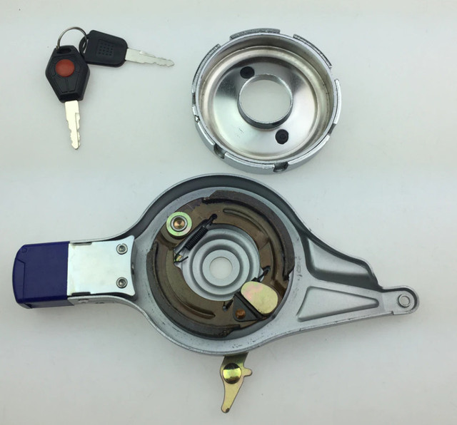
BTW, I don't really think I would trust any instructions Erider could provide, even if they would help. If you look at this document
https://eriderbikes.com/wp-content/uplo ... L-18-4.pdf
you'll find a section near the end that says "Do not be concerned that you are left with surplus screws and/or bolts."; when they have no way of verifying that the end-user has followed all the instructions for assembly correctly, and there could well be major required parts left over that could cause vehicle failure while riding.
Yes I have noticed Erider are not all that helpful
I dont know where I could get a male deans connector and about 80CM of wire with a ring connecter at other end as cant see ebay or amazon having leads like that. I know I am going to need a new phase and hall sensor wire as the one on wheel dont look good
I can't follow the results you have given as there is not nearly enough information to know what you are testing or what results you got, so I can't tell you anything about what they might mean.
It sounds like you were testing the phase wires of the motor itself, comparing them to the battery negative, first without power and then with power. I don't know of any test like that that needs to be done, based on what we've talked about so far. If you are doing some other test, there isnt' enough info to tell which one or how it was being done or what the results are.
I was testing from this page here https://ebikes.ca/learn/troubleshooting.html
for blown FETS as it says phase wires. the 3 phase wires from the controller was not fixed to those yellow junction boxes when I tested them also the other 3 wires wasnt too. the thick red, no 1 black no 2 and thin red no3 all those 3 wires go to controller
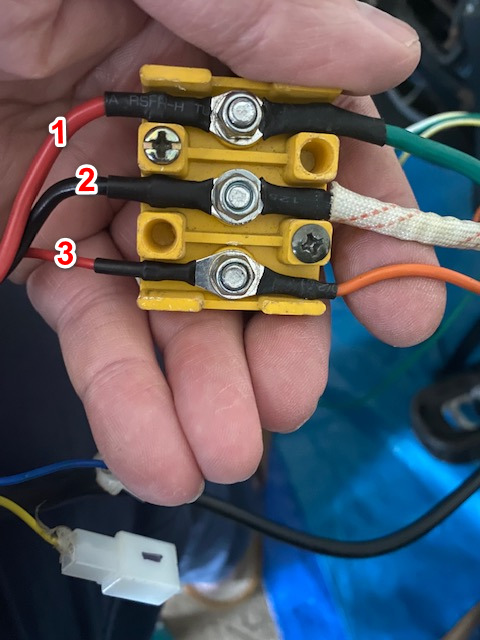
What do you mean, exactly, by "on the display I could see movement"? Is there something on the display that shows the throttle movement changing? Or do you mean some other kind of movement?
Where exactly was the throttle connected, and how?
What I mean is after I had taped up that copper wire you mentioned, and fitted wheel back on I just thought I would test if moped would start and I connected throttle a thumb one as thats all I have atm apart from a old grip one from my electric bike, but thats only 24 v one. but still same 3 wires. the throttle was connected to controller and I mean on the moped speedo screen when I moved throttle it said 13 Km/h so throttle must be working then
No, it's not. But you don't need to remove that freewheel to do any wiring, motor disassembly, repair, etc. It is mounted to the cover, and just stays there.
The only normal reason to remove it is to replace it if it is broken (if pedalling doesn't make the rear wheel spin, or if making the rear wheel spin forces the pedals to move even if you try to hold them still).
But I do need to remove that flywheel cog as how can I remove the side of motor case to access all the wires to check as if you look here I cant see wires as case wont come off as flywheel is stopping it

If you do need to remove it, then this is the type of tool used, along with the proper size wrench:
Yes I have ordered one now thanks
You said that the add-on cable wires were only connected at the motor, and were just taped off at the controller end. Were they individually taped off, so that they could not touch each other? Or were they taped off together, so that the copper in the wires was touching each other?
That addon wire like i said I found it behind the controller when I was removing moped panel to access all wires. it was taped at very end of cable. and also taped down to back of moped with duck tape so wasn't even attached to anything.
I forgot to mention but have you seen these Gel connectors, https://www.ebay.co.uk/itm/352017372663
I just tried on a piece of wire, and checked continuity and it was ok. I think you have to wait until the gel hardens like rock. would these be ok for moped wires of would you solder
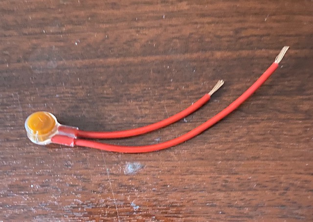
This listing is for a pack of 10 Comlynx jelly crimps.
Pack sizes available are 10, 20, 30, 40, 50, 60, 70, 80, 90, 100, 200, 500, 1000. If you require one of these quantities, please select one of the links lower down in the picture.
These crimps are designed to join 0.5mm telephone wire, which is an industry standard telephone cable.
It can be used indoors or outdoors as the waterproof jelly stops the connection from corroding. They are better than screw terminals and don't affect your broadband signal.
You just press the orange bit and it pops gel over wires which harden
I asked ERider about a power lead and this is what the showed me
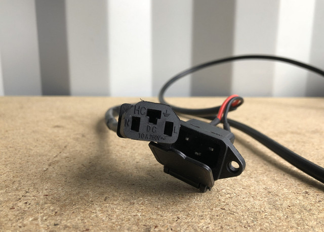
So that explains that from new that was power lead for the SLA batteries
They said it will cost. 20gbp. About $ 27 it’s no good to me
As like you said I need a male deans plug one end then ring terminal other end plus it’s not very long anyway
Ive made best I can a wiring diagram
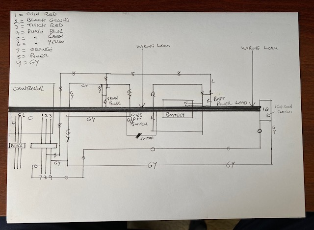
Hi amberwolf Im really stuck now with moped, as I cant remove freewheel to see wires other side I have bought a freewheel remover like you said, But when you turn it anti clockwise it wont unscrew also the freewheel goes around with it too, as its like pedalling backwards. but clockwise its obviously turning wheel then I think maybe the cog should be turned clockwise as you trying to unscrew freewheel anticlockwise
also I don't think the gear puller I have is any good for the bike, as its only small a 4" one
Ok I have now managed to remove freewheel but wires got cut so cant do much about that, will need a new cable now anyway
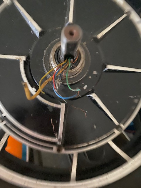
I have also now managed to free the motor too. but still cant see the cable inside as that has to be replaced

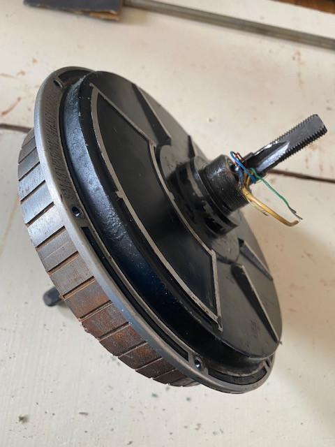


Hi again amberwolf I hope you will be coming back here soon as Im a bit stuck in a sense. well not too much, But I had to try and carry on myself as I didn't know if or when you would be back, anyway I've managed to remove freewheel side case and now have sorted the 3 phase wires, and 5 sensor wires. But as you can see in the picture with yellow circles around those 3 red wires those was not attached to anything. and that white wire has fused itself to that red wire above.
I have now ordered a new cable with 3 phase wires and 5 sensor wires. I also need to order a male deans plug and cable like you said
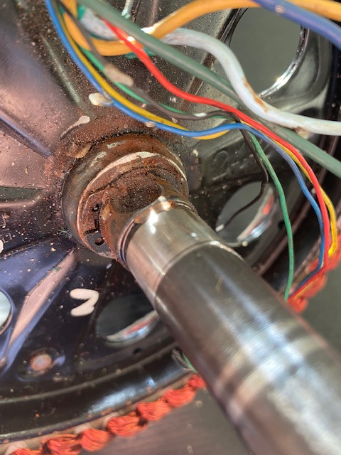
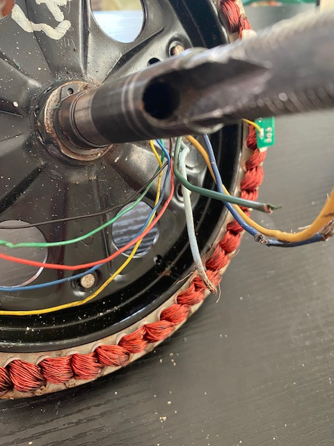
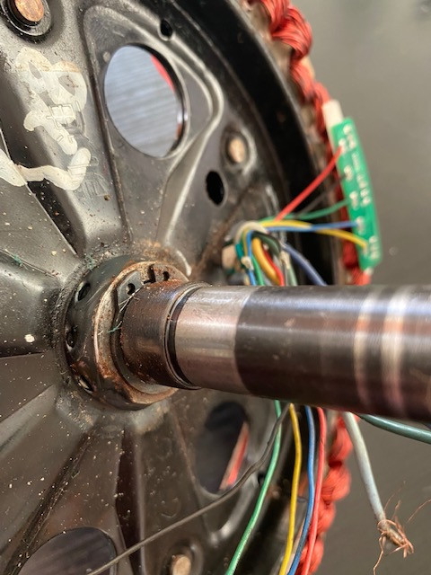

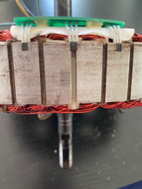
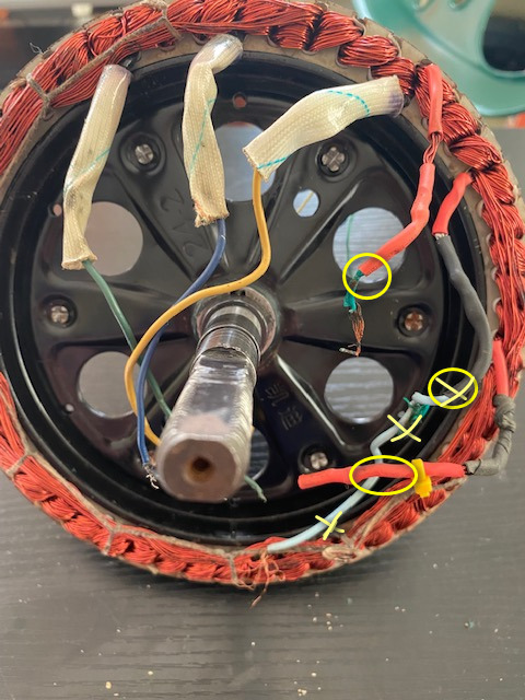
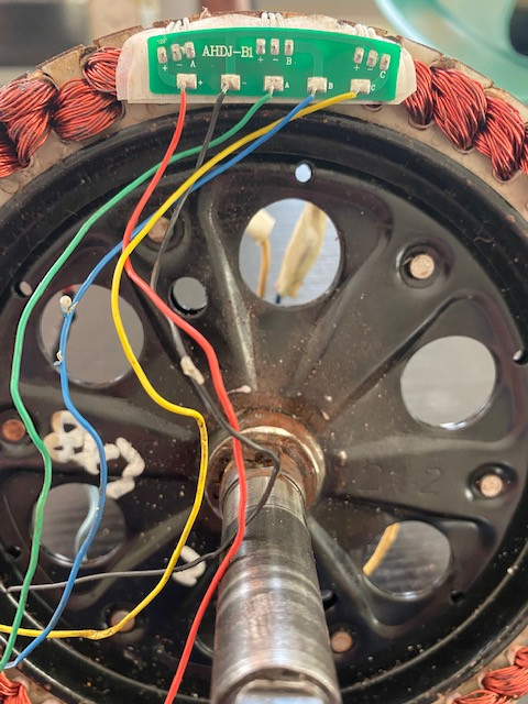
Hi again amberwolf I'm sorry to keep posting but not heard anything from you no more. so I had to go to another web site for help on moped, one person there told me who knows about motors said to join those 3 wires together what's in the yellow circles in previous picture above as they are the end wires of those 3 phase wires. which when I did continuity tests yes they are, so now I have soldered those 3 together, and hopefully when new cable arrives it should run motor well fingers crossed
btw hope you are well. and once again sorry if I have posted a lot but just wanted to keep you updated


Just to let you know amberwolf moped is now working fine it was because the ends of phase wires wasn’t joined
Hope you are ok and many thanks for all your help
Similar threads
- Replies
- 3
- Views
- 301
- Replies
- 0
- Views
- 133
- Replies
- 1
- Views
- 453