
dpearce
1 W
Hello all, I am new to this forum, I just recently came across it and have been checking out everyone's bikes and have been learning a lot. I wish I had found it sooner, I could have saved a lot of money and time researching, and undoubtedly produced a better bike . Although I am a newbie noobie noob whatever, I have something to contribute, I present to ES my electric bike, it was built as a mechanical engineering senior design project with the help of two other M.E. students. It is not 100% finished yet, but it is functional, maybe 5-10% more work until I am satisfied. This bike was designed and built in less than 4 months. Consequently, without sufficient time to reinvent the wheel, the focus of this build was on something that the ebike world seems to be lacking, a purpose built structure, designed from the ground up to be uniquely integrated with off the shelf components. So here it is, hopefully this build can provide some useful information to the members here undertaking similar projects.
The structure's (chassis, frame) function is to act as a housing for the electronic components, support for the suspension and rider, and tie everything together in a sleek appearing package. The project was started with classification and rating schemes to systematically find good solutions for the requirements set forth, and the project was to be completed within the budget of $4000.
Specifications:
Total weight 90lbs
Carbon fiber monocoque frame, <9lbs.
Custom built swingarm ~2.5 lbs.
CR80 motorcycle front forks and rear shock, rear ratio is 3" wheel travel per inch shock travel with progressive rate geometry.
Setup to provide 9.5" suspension travel front and rear.
72V 10ah Lipo batteries, ~8lbs (as of now), but it was designed to accommodate at least 72v 20 ah, as well as another controller for a front hub motor.
26" x 2.7" tires on 26 x 2.5" rims
Hayes 203mm / 8" hydraulic discs
5 speed
BMC rear hub motor, V2T, 10ga phase wires up to axle exit
BMC 50A controller
consumption 20-40 watt*hr
Headlight, tailight, brakelight, Cycle analyst, moped plate.
Top speed around just under 30mph w/o pedaling
Cost $4000, could have been much cheaper had I found this forum sooner.
Future plans-Double battery capacity (to 20Ah) and add front hub motor.
One of the first steps in the design was to make a dynamic sketch in Solidworks (SW), a 2D geometry model defining the wheelbase, suspension vectors, wheel size, head tube angle, seat height, battery placement etc. From this basic geometry model, with no dimensions set in stone yet, a conceptual model was made, modeled around standard mountain bike parts.
conceptual geometry model (1st iteration, not actual dimensions or geometry used):
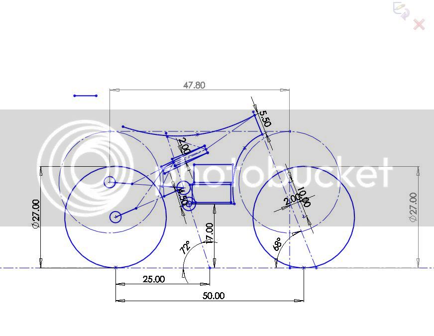
Since this was a clean sheet design, not based off any existing bike or motorcycle, geometry was designed specifically to keep the batteries as low and centralized as practical, while still retaining adequate ground clearance at full compression of the suspension. The extra speed and weight of the electric components were considered in the selection of the wheelbase, seat height and other dimensions, providing a good compromise between mountain bike and motocross dirtbike proportions and rider position, which truly makes this an Electric Motocross Bicycle.
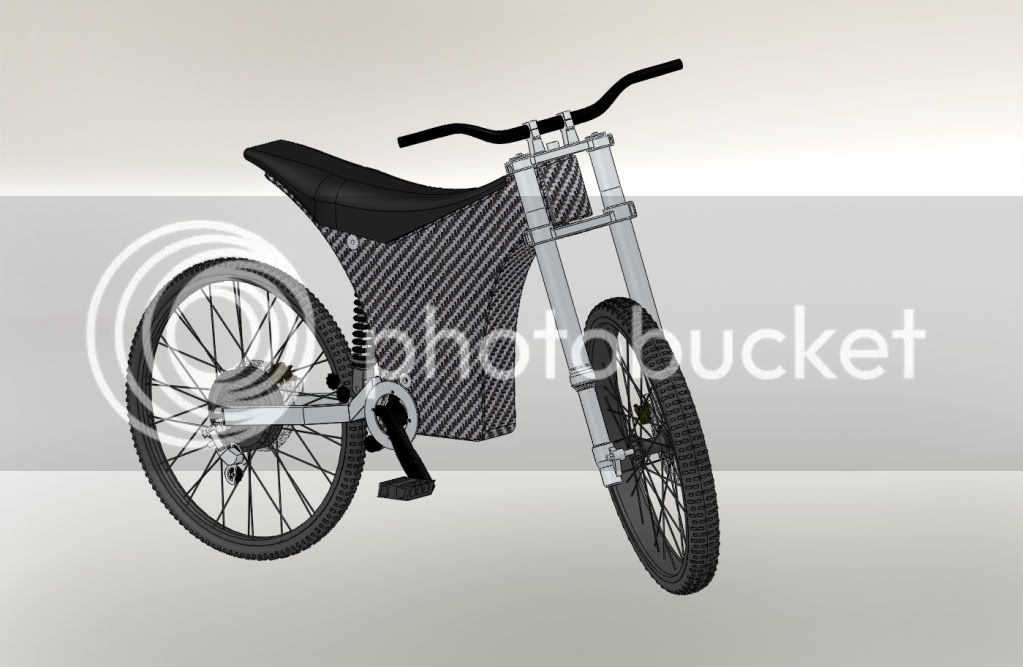
Solidworks Conceptual Model
Next was the embodiment of the design around actual parts that were to be used. Parts were selected to fulfill wished and demands withing the budget, after purchase parts were modeled as they became available in the order of their arrival. As more and more concrete dimensions became available from the presence of these parts, dimensions of some important parts were finalized with priority so they could be built first, since other parts might be dependent on their completion (for example frame inserts and sub components must be made before the frame)
The whole project would not have been possible without adhering to a strict production schedule in order to finish on time.
After checking clearances, refining suspension geometry, considering ergonomics, component access + servicability, etc., a detailed, fully functioning 3D model was made around the parts to be used. For a separate course, Analysis and Design of Machine Components, analysis was performed with the aid of Solidworks finite element analysis software, with a focus on critical areas of structural components, to ensure safety and durability during the intended use and abuse.
Once satisfied with analysis results the conceptual model could start to be realized in more detail.This model was then used to design and build the parts needed to make everything compatible, such as those shown below. In the detail design phase things such as hardware selection, chain path, bearing selection, etc. were determined so we don't find any surprises when we start to assemble things.
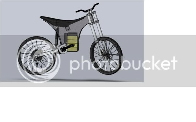
Transparency showing possible battery configuration (72V, 20Ah)
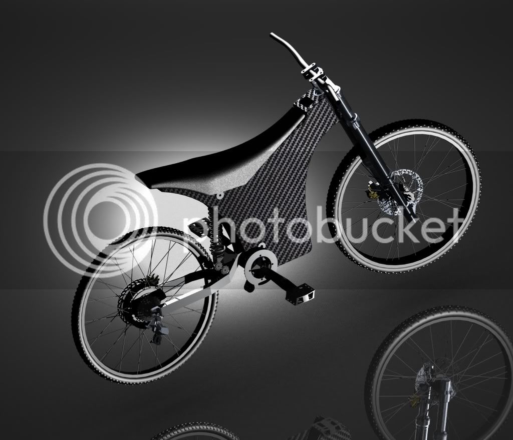
Rendering of detailed model:
Solidworks Animation:
[youtube]http://www.youtube.com/watch?v=UHsjXhiDpTY[/youtube]
Some parts made on the lathe:
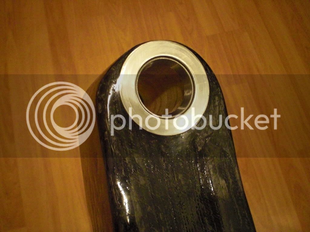
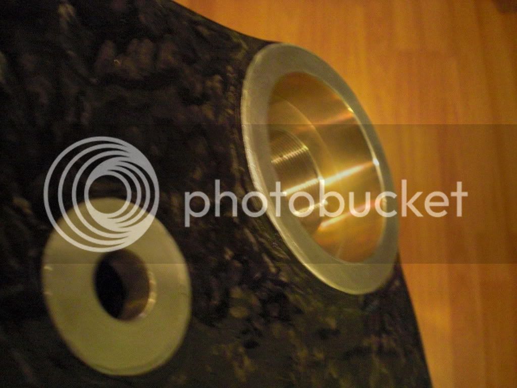
Machined head tube to accept CR80 forks, bottom bracket shell to accommodate raceface external bearing downhill cranks, and other frame inserts.
Knurled finish to help with adhesion of the composite, alodine coated to prevent corrosion
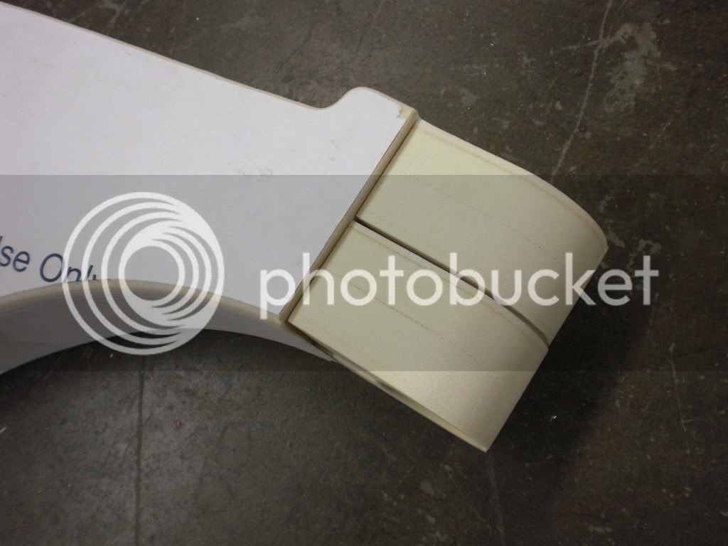
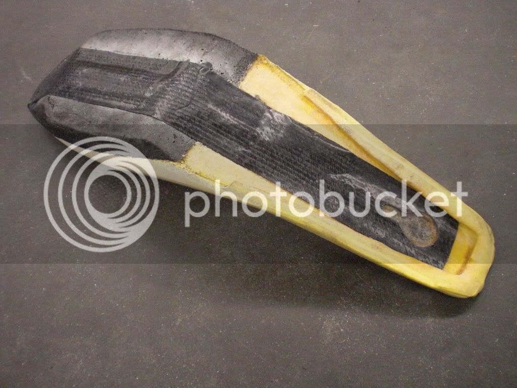
Positive frame mold:
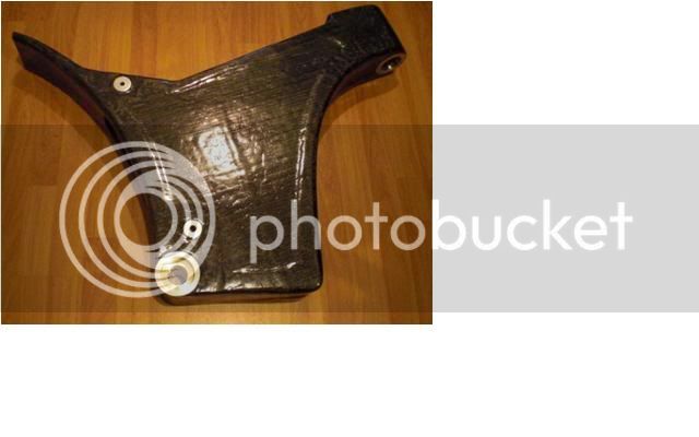
Swingarm pivot / bottom bracket frame sub component
Staggered layers of carbon fiber bottom layer are oriented 0-90, 2nd layer is 45-45, but with this stuff each layer also already has built in 0-90 and 45-45 degree fiber orientations.
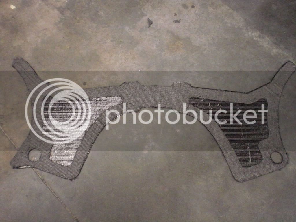
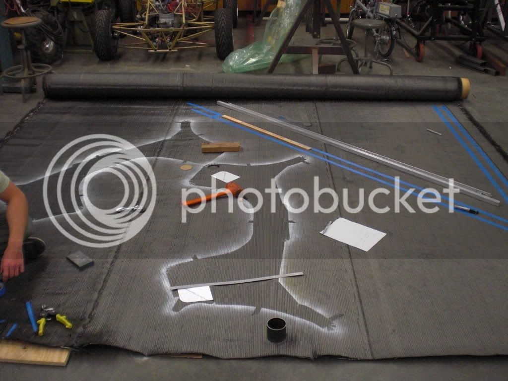
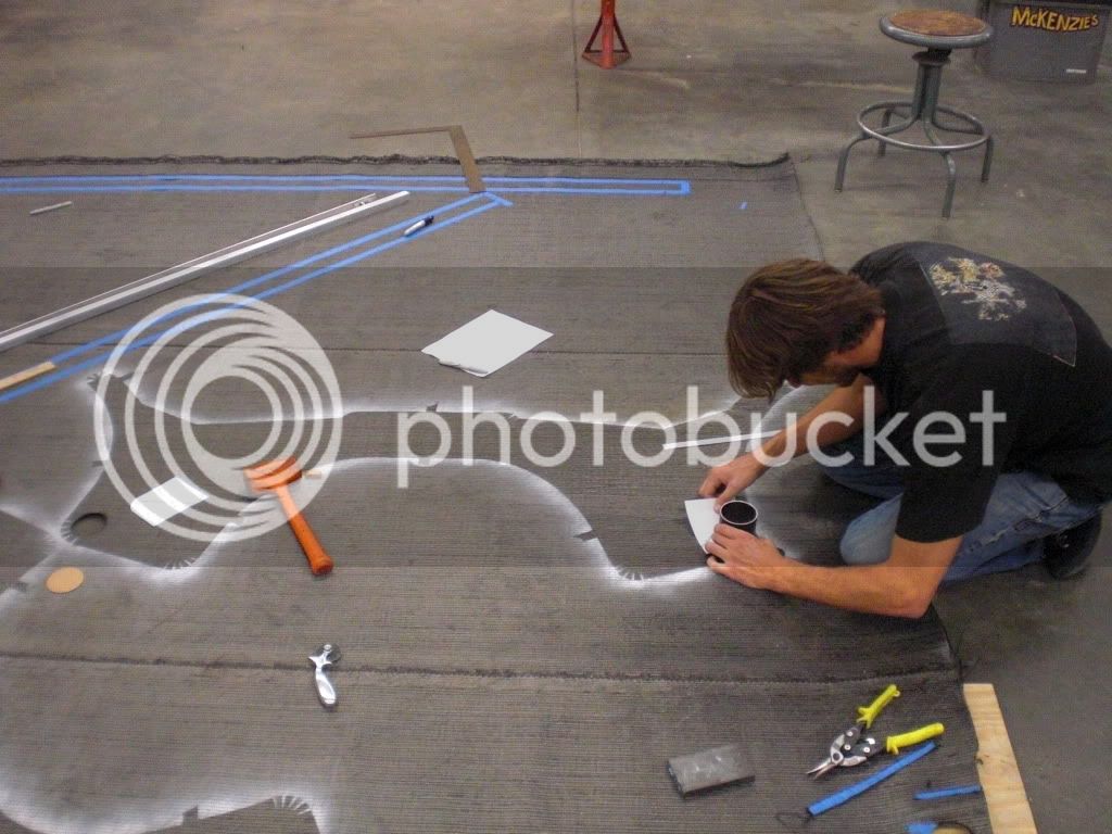
Here is a picture cutting the patterns out that demonstrates the different orientations. 1:1 patterns were printed on paper and traced onto the carbon fiber to be cut out. Using wet layup methods there is a little bit of leeway with these dimensions, but too much would be better than too little here, since it is easy to cut off excess after it cures.
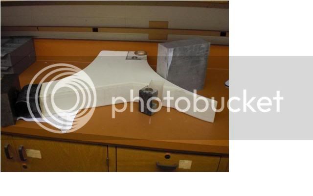
Self Jigging frame mold, with reinforcements prebuilt in to subcomponents. Eliminates need for external jig to hold inserts in during curing, which would complicate the vacuum bagging.
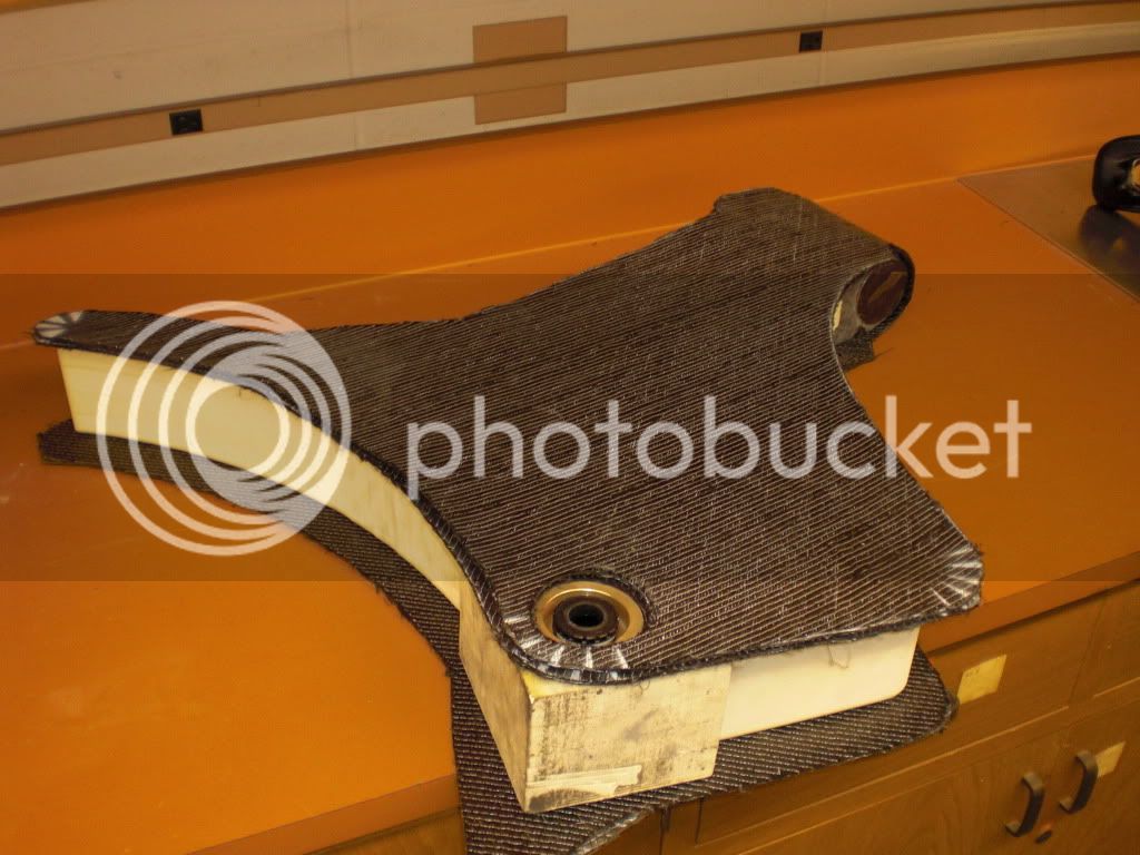
There are 2 layers around the edges of the frame, and 1 layer in the large areas subject to dominant shear loads. 1 layer cured with vacuum bag = ~1/16", 2 layers ~.125". In some places the layers are stacked up to as much as 3/8" thick. Samples were cured and tested for integrity and dimensional consistency, since many parts are designed around these carbon layer thicknesses.
This picture is a laser scan of the actual frame superimposed over the computer model, showing the dimensional variances.
Laser Scan color map: Different colors represent different dimension variations
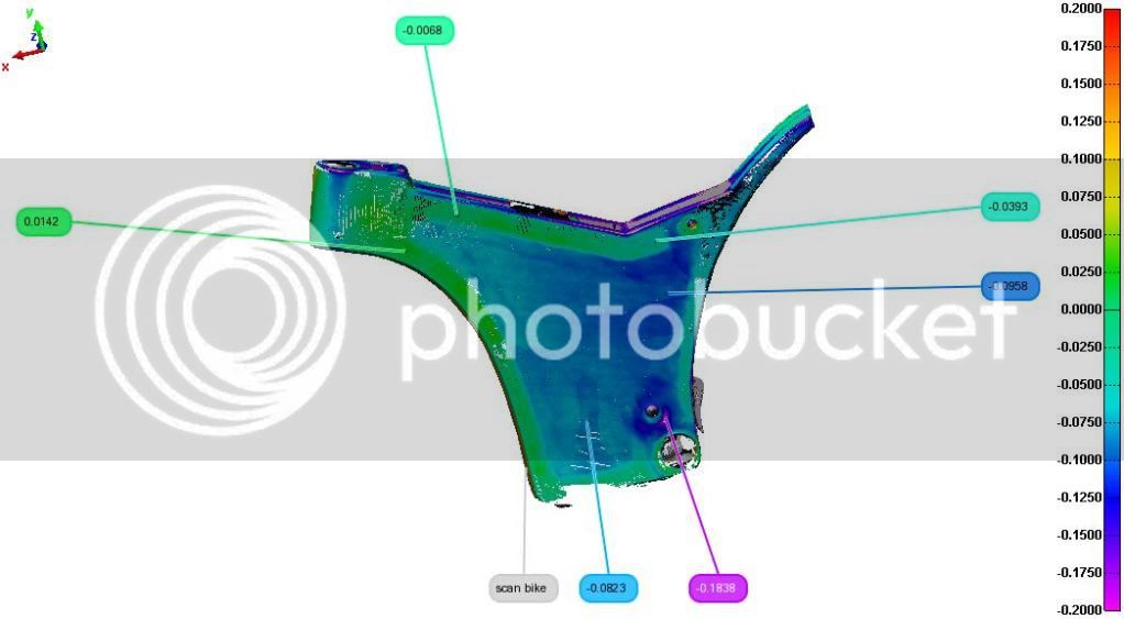
Courtesy of Polyworks
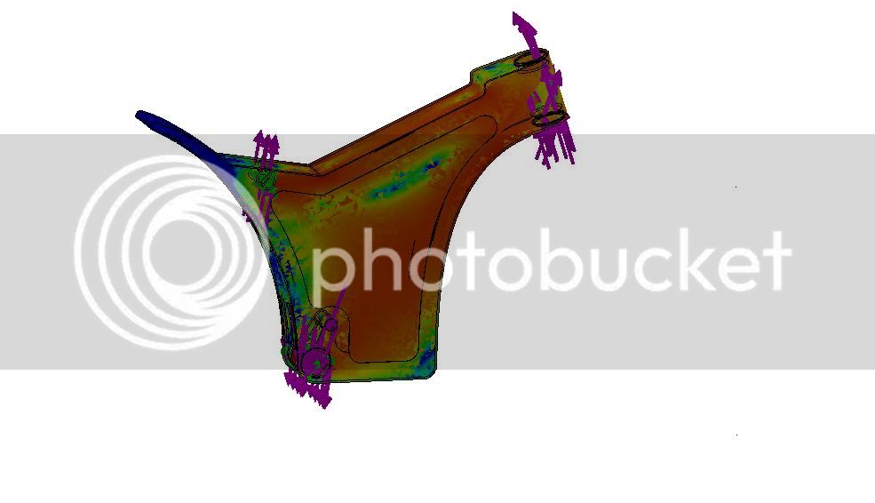
Factor of safety color map. The numbers here are not what we were interested, just the qualitative data that can be interpreted from these tools, that can give an idea of where the stress concentrations and critical areas are, where reinforcement may be necessary and where material may be removed. With carbon fiber being so light weight penalties were acceptable, broken frames are not, so reinforcements were made accordingly.
Finished Frame:
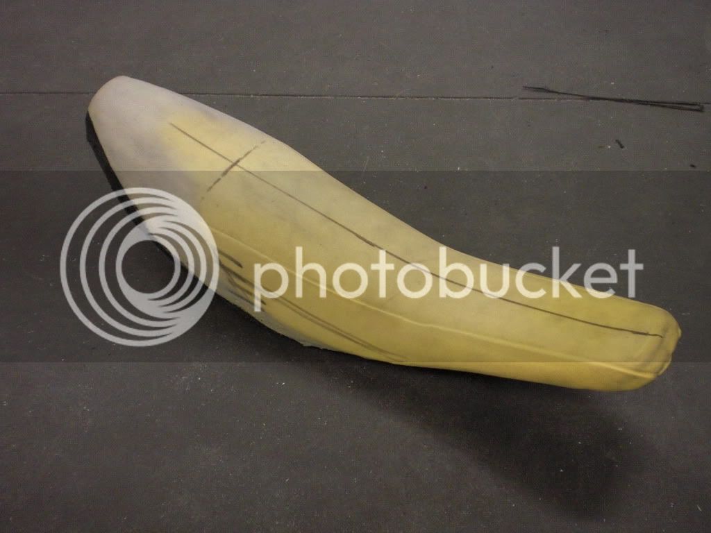
Custom seat made from modified MX bike seat.
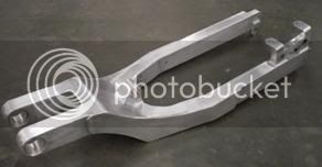
Finished Swingarm, built with 6061 rectangular aluminum extrude and plate, machined lower shock mount, brake caliper mount, pivot bushing mounts, and dropouts (3/8" thick). Welded in a jig, then ground smooth, then taken to be heat treated back to T6 condition and straightened. (Thanks to Newton heat treating, City of Industry, CA.)
computer Model:

Finished Swingarm:
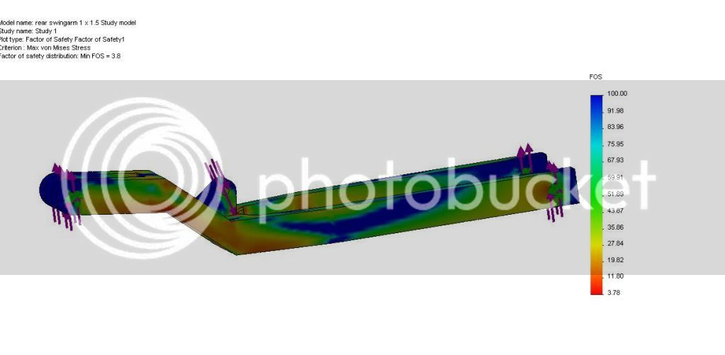
Simplified swingarm model factor of safety map. With known materials (6061 T6), and uncertain dynamic loading, the swingarm was designed to have a safety factor of about 4. However the model is very simplified, and the results are trivial without some sort of real world validation. Again here the results are useful quantitatively, showing that the highest stress areas are in the middle of the swingarm around the shock mount and at the corners. The Model also does not take into account material discontinuities due to welding. From there large fillets were added in the areas of highest stress, and the swingarm was reinforced further, again with safety being more of a concern than weight.
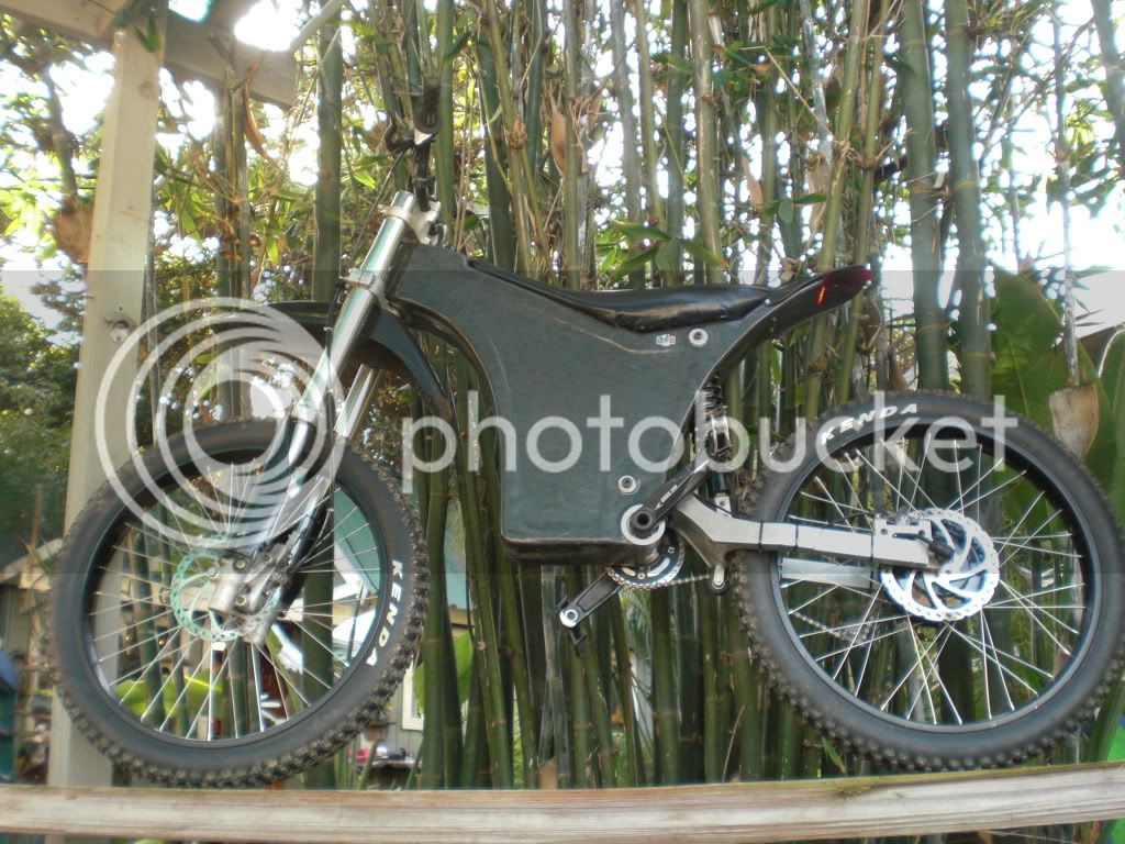
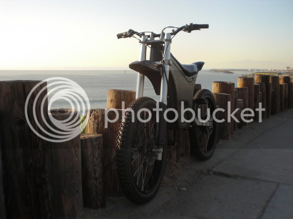
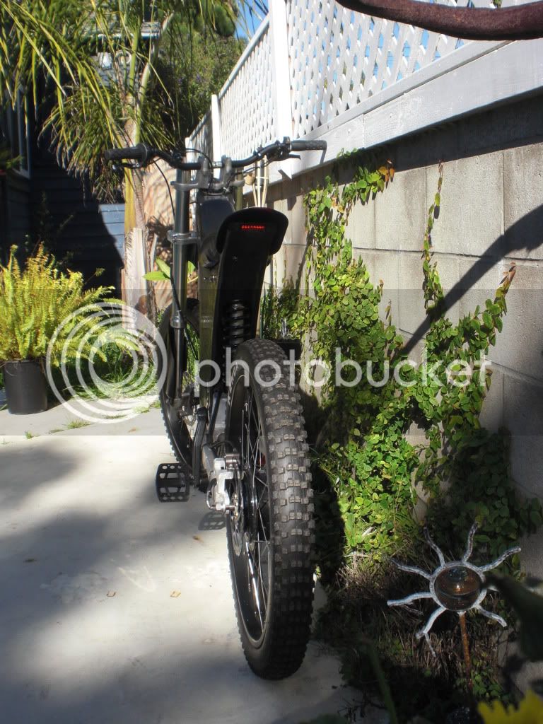
Finished Bike:
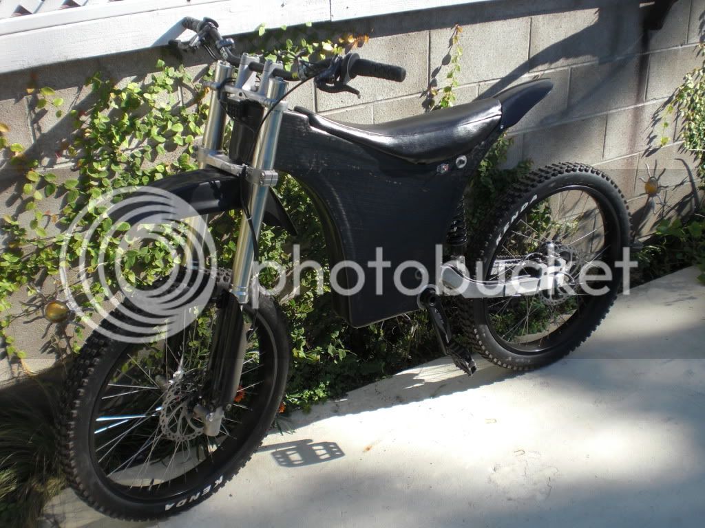
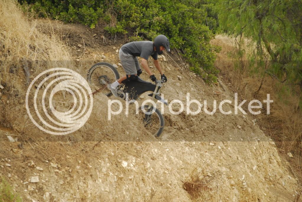
I have about 100miles on it so far, mostly street with light off roading, up + down some stairs here and there. I have been monitoring temperatures and all seems ok, but so far I have trying to use the power sensibly. We will see how long the motor holds up, I plan on getting the front hub motor and extra battery capacity to ease the load, and for steep hill climbing, and I still have set up the suspension better for me, along with the never ending list of other things that have to be done. Right now I am just enjoying riding it so it is hard to get back to working on it!
The structure's (chassis, frame) function is to act as a housing for the electronic components, support for the suspension and rider, and tie everything together in a sleek appearing package. The project was started with classification and rating schemes to systematically find good solutions for the requirements set forth, and the project was to be completed within the budget of $4000.
Specifications:
Total weight 90lbs
Carbon fiber monocoque frame, <9lbs.
Custom built swingarm ~2.5 lbs.
CR80 motorcycle front forks and rear shock, rear ratio is 3" wheel travel per inch shock travel with progressive rate geometry.
Setup to provide 9.5" suspension travel front and rear.
72V 10ah Lipo batteries, ~8lbs (as of now), but it was designed to accommodate at least 72v 20 ah, as well as another controller for a front hub motor.
26" x 2.7" tires on 26 x 2.5" rims
Hayes 203mm / 8" hydraulic discs
5 speed
BMC rear hub motor, V2T, 10ga phase wires up to axle exit
BMC 50A controller
consumption 20-40 watt*hr
Headlight, tailight, brakelight, Cycle analyst, moped plate.
Top speed around just under 30mph w/o pedaling
Cost $4000, could have been much cheaper had I found this forum sooner.
Future plans-Double battery capacity (to 20Ah) and add front hub motor.
One of the first steps in the design was to make a dynamic sketch in Solidworks (SW), a 2D geometry model defining the wheelbase, suspension vectors, wheel size, head tube angle, seat height, battery placement etc. From this basic geometry model, with no dimensions set in stone yet, a conceptual model was made, modeled around standard mountain bike parts.
conceptual geometry model (1st iteration, not actual dimensions or geometry used):
Since this was a clean sheet design, not based off any existing bike or motorcycle, geometry was designed specifically to keep the batteries as low and centralized as practical, while still retaining adequate ground clearance at full compression of the suspension. The extra speed and weight of the electric components were considered in the selection of the wheelbase, seat height and other dimensions, providing a good compromise between mountain bike and motocross dirtbike proportions and rider position, which truly makes this an Electric Motocross Bicycle.
Solidworks Conceptual Model
Next was the embodiment of the design around actual parts that were to be used. Parts were selected to fulfill wished and demands withing the budget, after purchase parts were modeled as they became available in the order of their arrival. As more and more concrete dimensions became available from the presence of these parts, dimensions of some important parts were finalized with priority so they could be built first, since other parts might be dependent on their completion (for example frame inserts and sub components must be made before the frame)
The whole project would not have been possible without adhering to a strict production schedule in order to finish on time.
After checking clearances, refining suspension geometry, considering ergonomics, component access + servicability, etc., a detailed, fully functioning 3D model was made around the parts to be used. For a separate course, Analysis and Design of Machine Components, analysis was performed with the aid of Solidworks finite element analysis software, with a focus on critical areas of structural components, to ensure safety and durability during the intended use and abuse.
Once satisfied with analysis results the conceptual model could start to be realized in more detail.This model was then used to design and build the parts needed to make everything compatible, such as those shown below. In the detail design phase things such as hardware selection, chain path, bearing selection, etc. were determined so we don't find any surprises when we start to assemble things.
Transparency showing possible battery configuration (72V, 20Ah)
Rendering of detailed model:
Solidworks Animation:
[youtube]http://www.youtube.com/watch?v=UHsjXhiDpTY[/youtube]
Some parts made on the lathe:
Machined head tube to accept CR80 forks, bottom bracket shell to accommodate raceface external bearing downhill cranks, and other frame inserts.
Knurled finish to help with adhesion of the composite, alodine coated to prevent corrosion
Positive frame mold:
Swingarm pivot / bottom bracket frame sub component
Staggered layers of carbon fiber bottom layer are oriented 0-90, 2nd layer is 45-45, but with this stuff each layer also already has built in 0-90 and 45-45 degree fiber orientations.
Here is a picture cutting the patterns out that demonstrates the different orientations. 1:1 patterns were printed on paper and traced onto the carbon fiber to be cut out. Using wet layup methods there is a little bit of leeway with these dimensions, but too much would be better than too little here, since it is easy to cut off excess after it cures.
Self Jigging frame mold, with reinforcements prebuilt in to subcomponents. Eliminates need for external jig to hold inserts in during curing, which would complicate the vacuum bagging.
There are 2 layers around the edges of the frame, and 1 layer in the large areas subject to dominant shear loads. 1 layer cured with vacuum bag = ~1/16", 2 layers ~.125". In some places the layers are stacked up to as much as 3/8" thick. Samples were cured and tested for integrity and dimensional consistency, since many parts are designed around these carbon layer thicknesses.
This picture is a laser scan of the actual frame superimposed over the computer model, showing the dimensional variances.
Laser Scan color map: Different colors represent different dimension variations
Courtesy of Polyworks
Factor of safety color map. The numbers here are not what we were interested, just the qualitative data that can be interpreted from these tools, that can give an idea of where the stress concentrations and critical areas are, where reinforcement may be necessary and where material may be removed. With carbon fiber being so light weight penalties were acceptable, broken frames are not, so reinforcements were made accordingly.
Finished Frame:
Custom seat made from modified MX bike seat.
Finished Swingarm, built with 6061 rectangular aluminum extrude and plate, machined lower shock mount, brake caliper mount, pivot bushing mounts, and dropouts (3/8" thick). Welded in a jig, then ground smooth, then taken to be heat treated back to T6 condition and straightened. (Thanks to Newton heat treating, City of Industry, CA.)
computer Model:
Finished Swingarm:
Simplified swingarm model factor of safety map. With known materials (6061 T6), and uncertain dynamic loading, the swingarm was designed to have a safety factor of about 4. However the model is very simplified, and the results are trivial without some sort of real world validation. Again here the results are useful quantitatively, showing that the highest stress areas are in the middle of the swingarm around the shock mount and at the corners. The Model also does not take into account material discontinuities due to welding. From there large fillets were added in the areas of highest stress, and the swingarm was reinforced further, again with safety being more of a concern than weight.
Finished Bike:
I have about 100miles on it so far, mostly street with light off roading, up + down some stairs here and there. I have been monitoring temperatures and all seems ok, but so far I have trying to use the power sensibly. We will see how long the motor holds up, I plan on getting the front hub motor and extra battery capacity to ease the load, and for steep hill climbing, and I still have set up the suspension better for me, along with the never ending list of other things that have to be done. Right now I am just enjoying riding it so it is hard to get back to working on it!
