Falco e-Motors

Punx0r said:
I'm not saying you can't have a controller inside a motor that will last five years. You just need to use sufficiently over-rated (and expensive) components to ensure that they will survive despite the deleterious effect the heat will have on them. That is inefficient, though.

Unless you have superconducting components, or the inside of your motor is somehow colder than ambient then an in-motor controller cannot be more energy efficient.

This is definitely the traditional and conventional understanding of marrying a controller and motor together. We do not use over-rated or super-conducting components.
 
Of course motor/controller built in can deliver and sustain 1000W as EPLUS shows us users.
But there is limit of course for internal controllers. I guess cannot be used for like 2000W FOR SURE.

It is all in design.
For this kind of power output heatsinking is crucial.
You must see pictures of EPLUS inside how is all design.
Solid stainless centre hub is part of heatsinking , this hub is exposed to outside on both sides .
Temperture inside is kept well within design limits by thermal protection, ever heard about thermal protection?
Again it is all in design.
On EPLUS you never even notice how thermal protection limits power output, it is so well implemented.
EPLUS does not do any cut offs, it GRADUALLY limits power output.

My are real life experiences with motor/controller built in, no theoretical musings.
I can touch and hold my hands against EPLUS hub for as long as want after 20km rides at power level 8 /out of 9 levels/, it is just warm.
During such rides I sustain 45km/h for kilometers and kilometers with power draws of only 1200 -1300W.
Center hub which connect to power electronics heatsink is always warmer but never hot to the touch.
 
Micro13car,

What does the knowledge that stainless is a poor conductor of heat for a metal do to your theories about why it's a better motor? That's why all metal cooking utensils don't burn your hand. Try that with an aluminum or copper spoon.

At stock power levels it's not surprising that they can get away with the controller in the motor, especially if it's truly more efficient. Some MagicPie's have controllers inside.
 
miro13car said:
Of course motor/controller built in can deliver and sustain 1000W
...
Temperture inside is kept well within design limits by thermal protection, ever heard about thermal protection?
Again it is all in design.
On EPLUS you never even notice how thermal protection limits power output

Are these two statements not contradictory?

I have no problem believing that a reliable controller can be built into a motor and I'm sure that it's a good-quality product. My objection is to making unfounded claims about that are intuitively nonsense.

I ask "how can it be more efficient or reliable to have a controller inside the motor" (it being a relatively hostile environment).

I'm just looking for an answer based on general principles, but all I get is "haha! That is Trade Secret LOL". Which is unfortunate because it's exactly the kind of answer you get from people claiming to have invented an over-unity device.
 
Where I live it can sustain that power output on flat, I don't live in hot summers climate for sure.
in Arizona desert probably not.
nothing contradictory
OK it is not rusting "metal" to me , I can assure you it transfer heat well but sincerely I don't know what exactely metal it is.
 
Its not impossible to make a reliable in-hub-controller.

It could be argued that due to operating in warmer temps it won't be as efficient (due to RdsOn increases with temp) and that electrolytic caps will have a much shorter life expectancy.

Yet, still those aren't insurmountable obstacles. Leveraging the outstanding silicon options for FETs in the <100v range, solid-state caps and/or excellent polycap layout, combined with very low current per-phase leg, it seems entirely possible.

Unless anyone has evidence to support Falco controllers failing, I would give them the benefit of the doubt on the issue.
 
liveforphysics said:
Its not impossible to make a reliable in-hub-controller.

It could be argued that due to operating in warmer temps it won't be as efficient (due to RdsOn increases with temp) and that electrolytic caps will have a much shorter life expectancy.

I absolutely, 100% agree with this. The problem is that FalcoeMotors has denied this and, instead, appears to be claiming that placing the controller inside the motor without changing any other variables* makes it both more reliable and more efficient.

*He specifically denied derating components

So far we have established the following:

1) Their controllers are more efficient and more reliable because they are mounted inside the motor
2) The controllers are not affected by heat (hence no need to derate components)
3) The inside of the motor is not colder than ambient
4) They do not use super-conducting materials

"Extraordinary claims require extraordinary evidence"

"That which can be asserted without evidence can be dismissed without evidence"

I'm not trying to be a dick. I wouldn't badger a harmless hobbyist, but these are commerical claims the primary purpose of which is to persuade people to part with their money. For that reason they are morally and legally required to be true and honest. Whenever I make commerically-based claims or assertions I have always been able to justify them. I only hold others to the same standard.
 
Fun thread to read guys, ES at it's very best. On this topic, the comparison with BionX (another proprietary controller-in-motor system) came up a few times:
FalcoeMotors said:
It is a comparison with a 3-phase BionX motor. With BionX, you still have significant difficulty in pedaling. With Falco, the cogging torque frequency is much higher and the cogging torque drops 75%. That is pretty close to ZERO for all government purposes.

I just had chance a couple weeks ago to take apart a older BionX PL350 motor to wire it up with an external controller and test it out on the dyno setup. The net drag torque of the motor as a function of RPM looks like this:
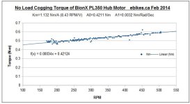
BionX Drag Torque.jpg

So from a stall it takes 0.42 N-m to turn the wheel, and this increases at 0.034 Nm for every 100 RPM as the wheel speeds up (which is quite a bit less than say the Crystalyte motors, that rise at ~0.15 Nm/100rpm).

If anyone here has a Falco motor and an ammeter of any kind hooked up to the battery pack, then it is fairly straightforward to get the same data and compare, no need for a fancy dyno setup, and much more quantitative than a spin-down test. Just run the motor at full throttle with the wheel off the ground, and record the voltage, current, and wheel RPM. Then release throttle a bit, and now record the new voltage, current, and RPM, and repeat that until the throttle is basically off.

For each data point, you have the electrical power going into the motor (V*A), and the motor speed. Since the current is pretty low, there is almost no I^2R losses in the copper winding, so it's fair to assume all the battery energy is going into overcomming the cogging/hysteresis drag of the hub*. For instance, say at full throttle the motor was drawing 1.1A at 38V and spinning the wheel at 340 RPM.

Input power = 38 * 1.1 = 41.8 watts
Power = Torque * RPM * 2Pi/60 => Torque = Power / (RPM * 2Pi/60)
So the drag torque of the wheel is 41.8 W / (340rpm * 0.105) = 1.17 Nm

We just need that for a couple different RPM points, as the data usually fits on a straight line and is fair to interpolate/extrapolate linearly. Anyone have a Falco setup and an ammeter** or CA connected to the battery and able to provide us some no-load power vs. RPM results? That's all it would take to get at least this piece of the data puzzle.

-Justin

*This test will show numbers that are a tiny bit high since it also includes the air drag of the spokes and tire, but the difference is pretty minute whether the motor is laced or not.
**At partial throttles when the wheel is spinning slowly, the currents will be fairly small so you want a current measuring device that resolves accurately to the nearest 0.01A
 
Lo and behold , I have a CA in line with battery to Falco motor, mounted on my bike. Plus I have a throttle hooked up. :D

I can do this measurement.

Bike and battery still in winter storage, so hold your horses, I'll get to it ASAP.

I also need to offset the quiescent power drawn from the internal controller and ca at zero rpm.
 
Bike_on said:
Lo and behold , I have a CA in line with battery to Falco motor, mounted on my bike. Plus I have a throttle hooked up. :D

OK awesome. If you set the wheel circumference to 1666mm, then the display will effectively show your speed as an RPM*10 reading too which makes the conversion straightforward. We'll stay tuned for the numbers!

I got to test ride a Falco setup at interbike last year and it felt great, but so do almost all the new direct drive motors coming online, from the transverse flux motors like Hoganas to just about any 3 phase BLDC drive running a sinusoidal or FOC controller. So it's hard to tell just from a qualitative ride if or how they stack up on specific terms like this, which is why the actual numbers you provide will be very interesting.

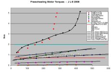
As another point of reference, FalcoMotors did mention that the Tidalforce which used a similar multi-phase technology had very high drag torque, and I was glad to see that acknowledged. Here's what it looked like, around 1Nm at stall and upwards of 2-3 Nm at biking speeds!
Tidal Force Drag Torques.jpg
You can see that when the system was turned off, more torque was needed to spin the wheel as the back-emf ends up powering the onboard controller which draws current and hence adds more drag. With the battery connected and on, the drag force is a bit less since the controller's quiescent power draw is supplied by the battery, but then at ~250 RPM it shot upwards as the controller went into regen to maintain 32kph speed limit.

The TidalForce motor wheel was totally smooth (no cogging torque ripple), which was an unusual ride experience back then, but it was a bit like pushing through molasses as far as the net drag. And I think that gets to the point that even though reducing torque ripple is good for making the wheel feel smooth and free of buzz or vibration, the impact on a rider is much more a function of the total core losses.
 
justin_le said:
...but then at ~250 RPM it shot upwards as the controller went into regen to maintain 32kph speed limit.

The TidalForce motor wheel was totally smooth (no cogging torque ripple), which was an unusual ride experience back then, but it was a bit like pushing through molasses as far as the net drag. And I think that gets to the point that even though reducing torque ripple is good for making the wheel feel smooth and free of buzz or vibration, the impact on a rider is much more a function of the total core losses.

Justin, it looks as if you were testing a standard 750W Tidalforce motor which limits top speed to 32 kph (20 mph) max. When it hits this wall, it does feel like molasses. This does not occur with the 1000W "X" version of the Tidalforce motor though. There is no forced regen since there is no 32 kph (20 mph) limiter.
 
Bike_on said:
Lo and behold , I have a CA in line with battery to Falco motor, mounted on my bike. Plus I have a throttle hooked up. :D

I can do this measurement.

Bike and battery still in winter storage, so hold your horses, I'll get to it ASAP.

I also need to offset the quiescent power drawn from the internal controller and ca at zero rpm.
Could you do a video spin test as well? Just throttle it up to a known speed, cut the power and let it spin until it stops. I think some people will understand that better.
 
Is this graph comparing 3-phase motors with 7-phase TIDAL FORCE?

BIONX with external controller? It is not BIONX anymore.
 
Did the Bionx measurement include the power from the controller? If it did , then I would expect a similiar Falco measurement, with an internal controller to be comparable.

Another Bionx could be tested like a Falco if it has a throttle option and power can be measured in line.

The internal controllers will skew the torque measurment because the power loss of the controller is added in and will bump up the numbers. It may be low losses and not matter much. True? For that matter, about any system will have one battery source and power used will be a combo of both motor and controller. I supose it depends on where the power measurment it taken. Before the motor,or before both?
 
Bike_on said:
Did the Bionx measurement include the power from the controller? If it did , then I would expect a similiar Falco measurement, with an internal controller to be comparable.

I zeroed the quiescent current draw out of the controller, but yes the measurement was done basically exactly the same way by measuring the no load electrical power draw and computing the drag force from that. In this case rather than varying the throttle I had it running full throttle and varied the supply voltage from 20V to 60V in order to change the RPM. But the results should be almost exactly the same at a fixed voltage supply while using the throttle to reduce the RPM.

The internal controllers will skew the torque measurment because the power loss of the controller is added in and will bump up the numbers. It may be low losses and not matter much. True?

This is only true IF there is no battery attached and the controller's quiescent power is coming from the motor back -emf voltage. Then there will be a slight additional drag as you saw with the Tidalforce hub in the first graph. But when you are measuring the power to turn the unloaded wheel based on the electrical energy going into the controller, it makes no difference whether you have in internal or external controller. Just zero the amps with the motor not spinning to cancel out the controller's supply current (usually just 30-50mA anyways), then what you see on the display will only be the additional amperage required to turn the hub.

For that matter, about any system will have one battery source and power used will be a combo of both motor and controller.

The power used to spin the motor unloaded is almost entirely do to core losses in the motor. Additional losses in the controller and windings at like 1A are totally negligible, so you don't really need to worry about the effect of these.
 
miro13car said:
Is this graph comparing 3-phase motors with 7-phase TIDAL FORCE?
The graph showing the tidal force torque was done differently, by actually measuring the torque on the axle with a load cell while spinning the wheel. So yes you are seeing the drag force of various 3 phase crystalyte motors compared with the 7 phase tidal force motor, all as measured mechanically on the axle itself while spinning the wheel at constant RPM with an external drive.

BIONX with external controller? It is not BIONX anymore.
Sure if you say, but the drag torque to spin a BionX hub motor isn't going to change whether it has the original or an external controller. Core loss is core loss and with the motor unpowered there's not much a controller can do to change that.

Anyways my point in this thread was just to say that there's no need to have long arguments about marketing claims of drag torque and whether they are BS or not, since most people here have the tools already on their bike to give a very accurate quantitative number. It's easy and precise to get from the unloaded power draw. So if Bike_on, or anyone else with a Falco system and an ammeter, can provide the power stats on their hub at a few different RPM's then we'd know how it actually compares.

The BionX PL350 data was provided to give context to the results, as Falco had already staged their comparison of cogging torque ripple in terms of BionX motor. But as Luke and others pointed out, the cogging torque ripple is of only marginal concern, it can reduce the subtle feeling of motor vibration as you bike but it doesn't affect the net drag of the hub to feel like it is truly 'freewheeling'. If you are claiming that a direct motor is virtually freewheeling, then you would want to back that up with a graph of the motor drag (Nm) versus RPM.

-Justin
 
... or just a video of it spinning down from full rpm.

...or you can withhold that information since the claim is a lie.. lol
 
neptronix said:
...since the claim is a lie.. lol


Yes. Even if the motor had no windings on the stator at all, if you have magnets passing in proximity to iron, you already have the great majority component of the core loss for pedaling speed ranges.

That claim was one of the reasons I wish them to kindly and correctly update product marketing so folks who may not know better don't believe it's going to be a direct-drive motor with the drag of a freewheeling type hub.

Justin- Would you be willing to take the time to test one on your dyno if I purchased it and had it delivered to you my friend?
 
Damm E.S. love fest ? Have been reading since may 2013 ( first post ) and I got a flyer 8mos. ago with a 500 -750 and 1000 watt. Why no talk of the 1000 watt motor. I ran down to the garage and couldn't find it yet. Thru these hubs are to expense for my blood.
 
FALCO:

1) beautiful kit! We love what you are doing but stop claiming zero resistance pedaling! Pure bullshit that turns many of us off. Why not claim lowest in the industry or something?

2) I don't blame you for not providing dyno curves. The reality is....even if you provide honest data, many of your competitors will not. Consumers are too trusting in this regard and the only solution is independent 3rd party testing. I don't trust data sheets for the most part.

3) great cell choice if what I read is true. Guys these are the nca cells and will last more than 5 years. Internal controllers are best as long as you monitor temps like Falco, so no problem there. Advertise the cells you are using!!!! " we use the Same chemistry and mfg as the Tesla Model S" How great will that sound to a customer????!
 
liveforphysics said:
That claim was one of the reasons I wish them to kindly and correctly update product marketing so folks who may not know better don't believe it's going to be a direct-drive motor with the drag of a freewheeling type hub.

Well, it could be that IF they are all the time powering the windings with just enough energy to overcome the core losses and resulting drag, but you could do the same trick with any motor so it's not really a testament to the motor design.

I would agree with your overall assessment here. The ebike scene needs some drive system options that are superbly well built and well engineered, that hold up to years of use without any of the routine failures we are so accustomed to. So if Falco is offering 5 year warranty and effectively guaranteeing against any controller or motor problems through excellent design and quality control, then that in and of itself is awesome and is only undermined when there is marketing material that is either misleading or reads like a bit of BS.

Justin- Would you be willing to take the time to test one on your dyno if I purchased it and had it delivered to you my friend?

That would be the least I would do for you ;). A dyno test would tells us the actual efficiency and torque output at different speeds, but in this particular case with a 5 phase controller it wouldn't make sense to then try and model the hub and put it on the simulator, as we have no idea what the internal controller is doing so all the motor model and assumptions on the simulator wouldn't apply.
 
justin_le said:
liveforphysics said:
That claim was one of the reasons I wish them to kindly and correctly update product marketing so folks who may not know better don't believe it's going to be a direct-drive motor with the drag of a freewheeling type hub.

Well, it could be that IF they are all the time powering the windings with just enough energy to overcome the core losses and resulting drag, but you could do the same trick with any motor so it's not really a testament to the motor design.

That is the first thing I thought also giving them the benfit of the doubt but then earlier in the thread falco specifically mentions running out of battery which leads me to believe this is not what they are doing. From thread:

"That really led to the 5-phase and why having no cogging is so important.

It is vital.

Also, When you run of battery, You could not pedal the Tidalforce or E+. It was a killer on your knees.

With Falco, you truly have ZERO resistance.

It is vital to have that ZERO resistance pedaling."

In any case we need to dyno system efficiency as that is all that matters in the end. Would be really cool to see the system eff of a china hub and china trap controller vs the falco system. That will sell it
 
FalcoeMotors said:
Also, When you run of battery, You could not pedal the Tidalforce or E+. It was a killer on your knees.

With Falco, you truly have ZERO resistance.

It is vital to have that ZERO resistance pedaling.
If, as Justin said, the Tidalforce motor had virtually no cogging then, Falco really do seem to be saying that their 5 phase motor has 'zero' parasitic losses.....

What is the slot/pole combination of the Falco motor? It's that which determines the number of cogging steps per revolution.
 
Ive always thought that claims of hubmonsters 94% ? efficiency were unlikely and lacking in evidence, and that obviously we had all just learn t to accept all that kinda stuff ? -its a slippery slope, but falco have just raised the bs bar even further with what amounts to a 100% efficiency claim, in fact this motor with zero resistance to spinning HAS to be the one to use on the front wheel to generate power from to recharge the batteries. :lol:

same applies to all extraordinary claims though, especially when intended for sales. -around here i would hope they require at least SOME evidence.?:?:

but this whole reality thing is a world away from what the marketing folks are increasingly used too.
 
Falco said in reference to cogging torque the value is so low that for "govermment purposes" it is zero

I have no problem with that just the zero resistance pedaling claim

Maybe the reduction in cogging makes the drag less noticeable but it is still there

Maybe the topology makes the drag lower, fine claim lowest in industry for direct drive

No way the drag is lower that a motor with a clutch, while saying the motor has zero resistance pedaling makes it seem so to the novice

Or course zero resistance does not exist
We are not trying to be pedantic

You could claim "zero" resistance if in fact it did have close to the same drag as a clutch motor over a wide speed range. Who would judge that? A rider who has ridden both. If the difference is noticeable to the average rider at 20mph then you cant claim it. This is just my opinion. Like I said I love your system, so dont get too worked up. Just know ES will not let this slip and what will happen is when you google FALCO this thread will be in the top google results. We can also create another thread with title "Falco e-motors bogus claims" and then link to it from multiple other forums and blogs and comment sections to optimize google search results for falco if you wish to continue playing this game

http://en.wikipedia.org/wiki/Search_engine_optimization
 
Back
Top