Kurt
10 kW
I have talk about building an electric motor driven kayak some time ago. Finally I have got around to starting this project. Starting with the purchase of a new double sit on top fishing kayak.I also now have a 40lb thrust 12v trolling motor.I have a large plastic 12v automotive battery box.At this stage I have gathered together 4 of my old sla ebike bricks that haven't been getting any use. They have been on float charge and should be in reasonable condition for initial testing. All 4 battery's give me 58ah at 12v.
The trolling motor is rated at 408w at 12v. So it will pull about 34 amps.I have only had the motor for about 20 min and after connecting it to a battery and testing all 5 forward speeds and 3 reverse to make sure it works. I started pulling it apart.
Why?.....Looking at how this motor regulates its speeds I think its going to be very inefficient.Inside the large motor housing is a series of coils and by directing the power through these resistive coils they are able to regulate the speed. The bad thing about this design is weather your running at speed 1 or speed 5 the little brushed motor will draw the same amps from the battery 34amps!!! The motor is a little over kill for my kayak so I want to run it at speed 1 or 2 most of the time. But what's the point if its going to draw the same amps as full speed.
So my plan is to bypass the speed coil and use electronic speed control for infinite speed control and better efficiency. When opening the plastic box at the top of the unit I found a simple multi position HD switch. The switch had two power in leads that connect to the battery. Then there is 4 wires running from the switch down the shaft top the motor. Two thick 10g wires and two 18g wires. I am assuming the two 10g wires would go directly to the motor for max speed. connecting a battery to them seems to confirm this. Using the other two 18g wires as + gives me two slower speeds.
But that's only 3 speeds from the 4 wires how do they get the other two speeds for a total of 5 ?
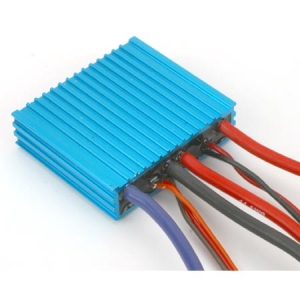
Anyhow that's not to important at this stage but still nice to know. What I plan to do is connect a cheap brushed speed controller to the 10g wires. I was thinking of something like a Ecrazyman 24v controller something with a 30 or 35a limit. The problem I see with this is that it would have a LVC set at 19v or so being a 24v controller.I'm sure I could bypass this LVC or get rid of it some how? So it would be a 800w 24v controller but at 12v it would give me my 400w I want.
Or perhaps just go with something like this I looks like its electronic and got to be more efficient then the resistive coils.
http://cgi.ebay.com.au/12V-30A-DC-M...cessories_Remote_Controls?hash=item2a00879748
That's my plan to start with as it seems simple cheap and easy.
I was also wondering how the motor would handle 24v or 36v. As long as I didn't go over the 408w say 36v with a 10 or 12a controller? Then I could use my headway lithium packs two of them for 36v 40ah
Any ideas or thoughts on the project or better suggestions to my plans would be great.
Kurt.


The trolling motor is rated at 408w at 12v. So it will pull about 34 amps.I have only had the motor for about 20 min and after connecting it to a battery and testing all 5 forward speeds and 3 reverse to make sure it works. I started pulling it apart.
Why?.....Looking at how this motor regulates its speeds I think its going to be very inefficient.Inside the large motor housing is a series of coils and by directing the power through these resistive coils they are able to regulate the speed. The bad thing about this design is weather your running at speed 1 or speed 5 the little brushed motor will draw the same amps from the battery 34amps!!! The motor is a little over kill for my kayak so I want to run it at speed 1 or 2 most of the time. But what's the point if its going to draw the same amps as full speed.
So my plan is to bypass the speed coil and use electronic speed control for infinite speed control and better efficiency. When opening the plastic box at the top of the unit I found a simple multi position HD switch. The switch had two power in leads that connect to the battery. Then there is 4 wires running from the switch down the shaft top the motor. Two thick 10g wires and two 18g wires. I am assuming the two 10g wires would go directly to the motor for max speed. connecting a battery to them seems to confirm this. Using the other two 18g wires as + gives me two slower speeds.
But that's only 3 speeds from the 4 wires how do they get the other two speeds for a total of 5 ?
Anyhow that's not to important at this stage but still nice to know. What I plan to do is connect a cheap brushed speed controller to the 10g wires. I was thinking of something like a Ecrazyman 24v controller something with a 30 or 35a limit. The problem I see with this is that it would have a LVC set at 19v or so being a 24v controller.I'm sure I could bypass this LVC or get rid of it some how? So it would be a 800w 24v controller but at 12v it would give me my 400w I want.
Or perhaps just go with something like this I looks like its electronic and got to be more efficient then the resistive coils.
http://cgi.ebay.com.au/12V-30A-DC-M...cessories_Remote_Controls?hash=item2a00879748
That's my plan to start with as it seems simple cheap and easy.
I was also wondering how the motor would handle 24v or 36v. As long as I didn't go over the 408w say 36v with a 10 or 12a controller? Then I could use my headway lithium packs two of them for 36v 40ah
Any ideas or thoughts on the project or better suggestions to my plans would be great.
Kurt.