spinningmagnets
100 TW
Tesla uses ultrasonic vibrations to connect a fuse-wire from the nickel-plated aluminum-core bus plates to each of the positive tips of the cells.
I'm starting this thread to park information I find about using fuse-wire. This has to do with fire-safety, and is something that every battery builder should care about. The video below is a builder making a DIY Tesla-style power wall as a power backup for his home, using salvaged laptop cells. Laptop 18650's are all low-current and medium-capacity, they compete on lowest price only, not performance. However, if the pack is large enough low cell amps can still add up to high pack amps.

I don't like the idea about soldering onto the tips of the cells, and would prefer any one of the methods used in other threads around here (spot-welding, magnets, no-solder contact pressure from poron foam). Be that as it may, regardless of your preferred connection method...I have embraced the idea that the series connections (which carry the full pack current) should be thick copper (raw or nickel-plated), and the parallel connections can be very thin, so...it is intuitive that the parallel connections should be the fuse-wire.
also, I don't think the positive end and the negative end needs to be using an identical connection method. I think on the broad and flat negative, there is merit to using button magnets to hold flat copper ribbon onto the cell-end.
In this particular application, he used thicker wire on the negative cell-ends, and it is the positive ends that have the thin 0.25mm wire as a fuse. He is using magnet-wire, so the enamel has to be removed, and this builder merely heats the wire at the location of the connection point with his soldering iron (perhaps not the most professional method, but it seems to work for him). Your individual cells' current (when shorted) will determine the minimum diameter of fuse wire that is appropriate (which needs to carry the max amps of current for one cell without getting too warm...more research is needed to make an acceptable chart, to be posted here when finished), and this should be balanced against the diameter of wire needs to be so it melts rapidly when full pack current is used. Using 2X the minimum diameter might be a useful starting point (10A cont at the cell/ 80A peak for the entire pack, so...wire gets warm at 15A and melts rapidly at 20A?). This is just a suggestion, and it may be amended in the future as more information becomes available.
Fast forward to 15:31 to see the fuse-wire being installed (finished negative side shown first)
https://www.youtube.com/watch?v=xOVEnbbhbRY
[youtube]xOVEnbbhbRY[/youtube]
Fast forward to 7:30 to see the cell-shorting wire melt test
https://www.youtube.com/watch?v=5hiQCD8LPcs
[youtube]5hiQCD8LPcs[/youtube]
Fast Forward to 5:14, wire-melt test at 6:06 (actual melt at 8:16)
https://www.youtube.com/watch?v=raBWFsPlx7w
[youtube]raBWFsPlx7w[/youtube]
Damian Rene, FF to 0:20 for fuse melt test
https://www.youtube.com/watch?v=c7PGLFgkdf4
[youtube]c7PGLFgkdf4[/youtube]
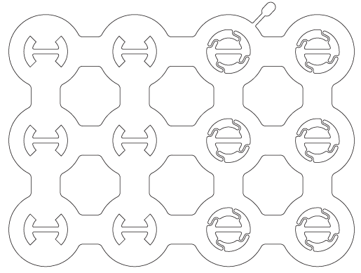
The pic below is the battery pack from an Alta electric motorcycle

I'm starting this thread to park information I find about using fuse-wire. This has to do with fire-safety, and is something that every battery builder should care about. The video below is a builder making a DIY Tesla-style power wall as a power backup for his home, using salvaged laptop cells. Laptop 18650's are all low-current and medium-capacity, they compete on lowest price only, not performance. However, if the pack is large enough low cell amps can still add up to high pack amps.
I don't like the idea about soldering onto the tips of the cells, and would prefer any one of the methods used in other threads around here (spot-welding, magnets, no-solder contact pressure from poron foam). Be that as it may, regardless of your preferred connection method...I have embraced the idea that the series connections (which carry the full pack current) should be thick copper (raw or nickel-plated), and the parallel connections can be very thin, so...it is intuitive that the parallel connections should be the fuse-wire.
also, I don't think the positive end and the negative end needs to be using an identical connection method. I think on the broad and flat negative, there is merit to using button magnets to hold flat copper ribbon onto the cell-end.
In this particular application, he used thicker wire on the negative cell-ends, and it is the positive ends that have the thin 0.25mm wire as a fuse. He is using magnet-wire, so the enamel has to be removed, and this builder merely heats the wire at the location of the connection point with his soldering iron (perhaps not the most professional method, but it seems to work for him). Your individual cells' current (when shorted) will determine the minimum diameter of fuse wire that is appropriate (which needs to carry the max amps of current for one cell without getting too warm...more research is needed to make an acceptable chart, to be posted here when finished), and this should be balanced against the diameter of wire needs to be so it melts rapidly when full pack current is used. Using 2X the minimum diameter might be a useful starting point (10A cont at the cell/ 80A peak for the entire pack, so...wire gets warm at 15A and melts rapidly at 20A?). This is just a suggestion, and it may be amended in the future as more information becomes available.
Fast forward to 15:31 to see the fuse-wire being installed (finished negative side shown first)
https://www.youtube.com/watch?v=xOVEnbbhbRY
[youtube]xOVEnbbhbRY[/youtube]
Fast forward to 7:30 to see the cell-shorting wire melt test
https://www.youtube.com/watch?v=5hiQCD8LPcs
[youtube]5hiQCD8LPcs[/youtube]
Fast Forward to 5:14, wire-melt test at 6:06 (actual melt at 8:16)
https://www.youtube.com/watch?v=raBWFsPlx7w
[youtube]raBWFsPlx7w[/youtube]
Damian Rene, FF to 0:20 for fuse melt test
https://www.youtube.com/watch?v=c7PGLFgkdf4
[youtube]c7PGLFgkdf4[/youtube]
The pic below is the battery pack from an Alta electric motorcycle