Gazelle easy glider 2007 battery charging pins?

Tyro

1 mW
Joined
Dec 1, 2011
Messages
13
Location
Lithuania
Hi there, I am coming there time to time to read about interesting thinks about e-bikes. Now i have problem and want help from you all, folks.

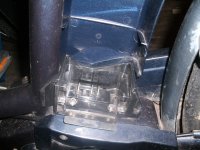
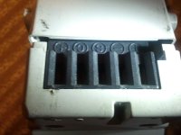
I have gazelle easy glider of year 2007 in my garage now. Not bike, but battery. I want to make a charging port for this battery, but i do not know which pins of battery is for charging. It have 5 pins slot on bottom named as T, -, S, C, +. On bike looks like there are 3 pins that connects to pins -, S, +. Maybe you can tell me which pins i have to use to connect chargers + and - to charge a battery? I am attaching photos of battery, slot, and bike's side. Maybe someone have this bike and can test charging.. :)
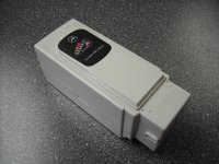
akku_easy_glider_72_ah.jpg

GEDC1884-resize.jpg

IMG_20121122_222058.jpg
 
Can the case be dissasembled? Once inside you can make better guesses as to what does what. Typical for many batteries is one + terminal, but one - for discharge and a second - for charging. Once inside, we may see wires going into the bms and to the battery that look similar to that, and then we'd know which wires to attach your new charging plug to.
 
Yes, i have opened the battery case already. BMS is very interesting, to battery there are going more than 10 wires (too much for 7s pack). The wire from outer pin named "C" is going into battery pack, then going out and soldered to BMS plate point that is named "CHG+". The "-" wire is soldered to BMS point that is named "CHG_G" that could be "charger_ground". The wire from slot "T" that looks like unused is soldered to BMS point whick name coulnd not be read easily. Looks like "Alle" or smth. "+" is positive for controller, and "S" I do not know what for. Max voltage measured from battery's outter point between "+" and "-" points is 2V. I am informed that battery is charged 80%, so "S" could be used as ignition to allow output voltage, but I do not know it is activated via positive or negative voltage.
 
I want to be sure before making experiments - it is really "C" pin for charger positive and "-" pin for charger negative should be used for charging. Voltage between them is 2 volts too. The connection error may cost me too much :| BMS is pretty interesting to find a substitution. The best idea is to measuring charging voltage on working charger or disassemble it to be sure. Maybe there are somebody who have charger for that type slot of battery ? :?
 
A bit hard for me to say for sure based on just text. Pics will help others comment as well. I'm just a moron at electronics beyond the simple stuff.

My guess would be that C is postive on your charger and that CHG_G is the negative. 10 wires to the bms makes some sense as well, 7 or 8 of em individual wires to the cells in the pack, leaving either two, one- one + or perhaps two - as is common. Should be at least 7 smaller wires to individual cells, plus more fat wires to carry discharge current.

Using your voltmeter, you may be able to probe at the individual wires at the bms, or the cells themselves and see if any are reading 0v or way too low volts. 80% charged could be 6 cells charged and one dead, which would shut off the bms power output.
 
Back
Top