Help identifying battery, controller, & charger manufacturer

HighNear90

100 mW
Joined
Jan 27, 2010
Messages
35
Location
Oxford, MS
Hey folks,

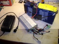
This is my first post here and I was wondering if you all could help me ID these parts.

I bought the bike off Craigslist and all I know is that the hub motor is from golden motor and the battery is 48v. The battery has some kind of blue fiber-like tape holding it together. The BMS (i guess it's a BMS) has yellow heat shrink. And the charger has 2 LEDs with only Chinese writing identifying them.

I opened the charger and re-soldered the power leads onto the board and replaced the fan which had only one blade left on it (you can see it in the background).

Any help would be HUGELY appreciated.

e-bikeparts.jpg
 

Attachments

  • e-bikeParts.jpg
    e-bikeParts.jpg
    122.6 KB · Views: 938
I would guess either infineon or crystalyte controller from the case.
 
The battery looks to me like a cylindrical cell lifepo4, typical of the ebay batterys known as duct tape packs. What ever it's size is should be considered it's max continous amps rate.

The charger is similar looking to many inexpensive sla chargers from ebay for electric scooters. Basicly a generic charger. The charging profile will have been adjusted for lifepo4 if it is a lifepo4 charger. Or it could be simply an sla charger. I had no problems using sla chargers to charge my lifepo4 battery for almost two years.
 
Great! Thanks Dogman,

The previous owner stated that it was a 10aH 48v pack. How many cells do you think are in there? Should I cut it open?

Also, the P.O. did not do a very good job soldering connections. I've got a good supply of Dean's Ultra and Anderson Power Poles, so I'll re-solder and crimp where needed.

THanks,
Leo
 
The battery has the same colored duct tape as the battery I got from the infamous lau chan, aka jimmywu, emma, 245300, eastunitedmusic, lifepo4.hk in July 08. At 48v it is most likely 7p16s 18650 saphion lifepo4 cells, about 7-8A capacity, 6-7 usable. Also, the Lau chan packs advertised as 48v20A were actually about 15-16A, etc...
The charger looks the same as the one supplied by lau chan with the packs, mine failed very early on, luckily for me GM supplied one with their kit but I had to adjust the voltage up a lttle bit to get the BMS to balance.
The BMS is likely Signalab ver1, re-covered with duct tape by the look of it.
The controller is a 15 FET 48v 1000w (33A max) "Standard" non-regen commonly supplied in golden motor kits.
That battery is way under-rated for that controller in its standard form. My battery pack was double the capacity of yours (2x 24v split packs, each 1/2 were the same dimension as yours) and got warm to the touch after some hard riding.
If it hasn't already been done I recommend removing one of the two shunts inside that controller, that'll bring it's amp draw down to about 20A, 3C is still way too high for the cells in that pack but might help its longevity a lot. I did this mod to one of my 15 FETs, to help with range though, still got to top speed, not as quickly though.
 
Awesome info oldhag,

I'll use the search to find out how to mod the controller and remove the shunts.

The BMS actually has yellow shrink-wrap on it. I think I might cut a little of the pack apart to see if there are any of those 18650 cells in there.

Thanks again,
Leo
 
er, umm, that's oldhaq. I was afraid that would happen one day, good chance it will again I s'pose.
Anyway, if you have a look at the 2nd picture in this thread, http://endless-sphere.com/forums/viewtopic.php?f=2&t=16286
top/left between the 1st and 2nd FET and the two lower capacitors are the two shunts. Get a hot iron to remove one of them, or preferably lift an opposite end of each then join the two in series.
Lau chan early on supplied iridescent blue shrink-wrap Saphion cells, later plain light blue no-name.
From my experience the Saphion cells have about 10% more capacity than the no-name and pink cells. The blue cells apppear to come from hk/guangdong and pink/flesh color from beijing.
 
Oh man, I'm sorry oldhaq. i should have paid more attention. I'm removing the case on the controller now. I'll post my results.
 
Oldhaq,

You were dead-on about the BMS. It's a Signallab.

I see the shunts and there's a HUGE blob of solder, looks really messy. I'll try to put them in series tonight. Any "gotchas" I gotta look out for?

Here are the pics:
ControllerShunt1.jpg

ControllerShunt2.jpg

BMS.jpg
 
Instead of reducing the amps of the controller to help the weak battery, it looks like the owner put solder on the controller shunt, increasing the amps of the controller.

Don't be too suprised if the battery is most usefull as a doorstop or boat anchor. a 10 ah lau chan battery is only good for about 300 watt motors. It may have seen some pretty harsh use already if the controller modification made it a 1000 watt bike.
 
Yeah dogman, you might be right about the battery. I think the PO used it hard.

I might just get (4) 6s 5AH 25C LiPos and wire them in a 12s2p configuration and then I won't have to worry about amp draw. I fly R/C planes and helis, so I have a few 6s balancing chargers. Do you see any problem with doing something like that?

Also, what do you think the voltage drop under load that 48v pack would be? So that I'm understanding, this is a 16cell pack and fully charged should be something like 57v, and nominal should be about 51v, and under load should be around 44v (assuming they act like A123 batteries with 3.6v full/3.2v nom/2.8v under 20C load per cell).....right?
 
No big deal about my nickname, I just thought I'd point it out 'cos it might have really got to me if it continued :( :twisted: , only kidding :wink:
As dogman points out the shunt has been soldered, the controller will suck more juice, which puts the batts under even more strain.
If you do happen to look inside the packs, if the shrinkwrap of any cells appears split due to shrinkage from overheating or any leaking, then there's likely damage done, but first test the voltage of each cell group on the BMS, if each is over 3.2v it might be ok. The duct tape appears to have been removed previously, so it may have already had repairs, or my guess is it was originally larger capacity and then the cell strings re-configured, hence the still soldered shunt which caused the previous owner to rebuild the pack from the salvaged cells and then decide to get rid of it all, without adjusting the shunt again.
That BMS is prone to losing FETs, it's recommended to solder them together with some copper wire strands too.
All said, I reckon the battery may soon fail again, best to use a better battery pack and use the power that the controller can currently deliver. :wink:
 
Thanks again for the time and info,

I'll test the cell groups tonight.

So would Lipo's work well in this situation?
 
OK, I tested the cell groups with a voltmeter and 15 were 3.15v-3.2v, but one was 3.02v. I'm going to give it a charge as soon as I redo the wiring and put on new APP connectors.

About the FETs on the BMS.....Let me search first before asking how to solder them together.
 
OK, I have to put heat shrink on the BMS today, so I need to know where to solder the copper wire strands. One question though......do I use something like stranded 16-18AWG and remove the covering? Or use like standard solid 14-16 gauge household wiring?

Please let me know if I'm on the right track with the picture below:

BMS_2.jpg
 
they are already soldered together where they are soldered down onto the end of the pcb. but from the looks of it you really should not have any problems. that is the v1 signalab and the controller is the old goldenmotor 36V shenzen type controller so i assume you have the goldenmotor too.
 
The main problem I've seen with these is sometimes the factory does a terrible job of soldering the fets to the board, causing a fet to fail from overheating. I've seen a new unit with one of the fets making virtually no contact at all with the board. Yours may be ok, but can't be sure how much use it has had already.
Yeah as in the pic, just solder-in any old copper wire across all the fets including to the P+ solder pad on the corner. It cant hurt to do it and will help to reduce the risk of the fets overheating.
Some more info in the following threads if you haven't found them yourself already, there was another good 'before and after' thread somewhere around here that I can't find now,
http://endless-sphere.com/forums/viewtopic.php?f=14&t=15696
http://endless-sphere.com/forums/viewtopic.php?f=14&t=8841&start=60
 
OK, I got some 12 gauge wire soldered across the FETS and the BMS re-covered with heat shrink. I put the battery on the charger and it only got to 55v fully charged. I guess I need to look and see how to modify the charger to output more voltage.

I put the hub motor on my bike today. Horribly off-center. I guess I'm gonna have to learn how to dish a rim.

Also, I finally read the inscription on the motor and it says "HBS-48V 1000W" Whoa!

Thanks again for everyone's help.

Oh, and I removed most of the solder from the shunt area on the controller using de-soldering braid. Long tedious process, but we'll see how it works out.

--Leo
 
Back
Top