Phoenix123
1 µW
- Joined
- Sep 23, 2019
- Messages
- 4
What up guys , my name is phoenix, new to the forum. Ive been putting together homemade electric bikes, carts, scooters ect. for years for me and my buddys, without any proper knowledge of larger scale circuitry. Im an IT technician and can build a computer of any type with my eyes closed. When it comes to wiring e bikes however i usually just trial and error it using what i know about electronics and common sense. Every setup Ive built has been from scratch, home made battery packs, home made drive systems from salvaged dc motors of various sizes with custom cut gears to adjust torque, and home made speed controller circuits from salvaged components.
Anyway I'm attempting to use an old hub motor with a random 48v controller from a scooter. the Battery is homemade from several laptop batteries. All samsung and panasonic 18650s individually charged and each cell in the series tested/balanced with a total output of 54v. (will this be sufficient?)
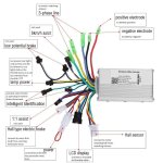
The controller has no labeling on any of the wires, the phase wires are straight forward enough assuming the colors from the hub motor correspond with the controller. i connected the hall sensor wires to their corresponding controller wires aswell. Ive attempted to wire on the throttle, but here's the main issue; the controller has multiple wires that have been spliced and i cant for the life of me figure out which wire goes where. All attempted combinations Ive tried do nothing, no sign off life what so ever. Was hoping someone might be able to help me figure out a working setup with what hardware i have, doesnt have to be great i just want the wheel to spin according to the throttle input. i do not have an lcd display of any kind for now. Am i completely messing something up? am i on the right track? Any help greatly appreciated.
sorry all the pics are sideways
Attachments
-
 20190923_230644.jpg229.3 KB · Views: 345
 -
 20190923_230908.jpg137.4 KB · Views: 344
 -
 20190923_230934.jpg89.2 KB · Views: 344
 -
 20190923_231025.jpg143.8 KB · Views: 343
 -
 20190923_231120.jpg102.5 KB · Views: 343
 -
 20190923_231159.jpg99.5 KB · Views: 343
 -
 20190923_231420.jpg231.3 KB · Views: 343
 -
 20190923_231557.jpg281.5 KB · Views: 343


