• Howdy! we're looking for donations to finish custom knowledgebase software for this forum. Please see our Funding drive thread

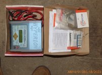
Help: my Hyperion 1420 exploded

rjoe

10 W
Joined
Sep 16, 2011
Messages
81
Location
Baltimore
I may have possibly accidentally connected the balance wires to the charger before powering it on... then when I connected the main battery power connectors, there was a lot of popping and smoke, and the main connectors melted together, so it when on for a little while.

I have some photos of the carnage. It looks like one FET in particular burned up. Please let me know if this is fixable. By the way, it's a EOS 1420i NET3 or whatever

This appears to be the only part of the board with damage. All the capacitors seem fine.
board.jpg


The FET in the middle of the picture melted to the rubber underneath. The others seem OK, just a little bit of burny-ness nearby on the big pads you can see in the first photo. That stuff wipes away easily.
fets.jpg


Here is a shot of the heatsink.
heatsink.jpg


I know some of you guys are Hyperion experts. Thanks a lot for your help.
 
id start by replacing the parts and go from there..

i believe you posted in the wrong section, i'll be moving your post to the correct place! 8)
 
from looking at the heatsink, i would say it is improperly designed so that mosfet just overheated because it had no contact with the heatsink.

if you look at the white goop underneath the mosfet that burned up, the silicone heat sink compound, you can see how thick the remaining goop is versus the amount of the goop underneath the 4110 next to it.

that should tell you everything about the poor design or manufacturing process itself. the mosfets on the end are so high off the pcb that the 3710 does not seat tightly against the heat sink when the pcb is clamped to the heat sink. jmho

i think the wbr30100 is a diode, you can google it. and the 4110 next to it is just a higher voltage power mosfet like the 3710. but check the body diode on it too and then go look at the gate resistor and driver for the 3710 and check continuity.
 
Was this lipo?
I think it may qualify for the catastrophic whoops thread. It is very relevant.

Hopefully just wants a new bit. They never cost much.
 
Did you miss the very first caution on the first page of the manual? Wonder why they put it in bold prin? Now you know.
ALWAYS power charger ON before you attach a battery to output or balance connectors.
 
friendly1uk said:
Was this lipo?
I think it may qualify for the catastrophic whoops thread. It is very relevant.
Lipo, lifepo4, sla, nicd, doesn't make a difference. When one fails to follow instructions, bad things will sometimes happen. Do you want to put all the blown chargers for lifepo4 packs, sla packs, nicd packs, etc. in a catastrophic whoops thread too. I'll guarantee there's been as many or more of them blown than rc chargers
 
wesnewell said:
friendly1uk said:
Was this lipo?
I think it may qualify for the catastrophic whoops thread. It is very relevant.
Lipo, lifepo4, sla, nicd, doesn't make a difference. When one fails to follow instructions, bad things will sometimes happen. Do you want to put all the blown chargers for lifepo4 packs, sla packs, nicd packs, etc. in a catastrophic whoops thread too. I'll guarantee there's been as many or more of them blown than rc chargers

Well non of the disasters relate to chemistry do they? Every one is somebody doing something wrong. That is what the thread is actually showing us. It is not lipo causing the problems, it is people not building packs properly. Yet still newbies come asking how to charge their packs, too be told get RC gear. The biggest cause of these disasters. Meanwhile, every proper bike you can point too uses a bms instead and no problems have been recorded there.

The op knew to turn it on. They just forgot. Should that really be blowing up your kit? No, it just makes the kit inappropriate. It is proper toy town.

The OP should post there "I used RC charging gear and complacently blew it up" imo. It would add value to the thread. I wouldn't call it off topic, as that is just about what all the posts say
 
The point is, that the same could happen plugging in the charger to a bms before plugging the charger into the wall for power. Either way is wrong. That his was an rc charger instead of a bulk charger is just a coincidence. Same could and has happened with chargers for BMS's, so get off your ignorant kick of how we'd all be better off using a BMS. Guess if you jump in your car throw it in reverse and back through the garage door, you'll blame the car designer for not opening the garage door for you when you put it in reverse. Sometimes people just have to be responsible for their own actions.
 
I mean I have hook up the main battery before plugging the charger and or sense wires. I have 24s lifepo4 homemade battery. So more changes of miss conecting.
 
it can be fixed. you can learn from this. if you look at the traces and where the current flows through that mosfet. post up close up pictures if you wanna. of the traces on the backside especially.

on a mosfet, these TO220 packages, the legs are gate, drain, source from left to right. you turn it on by applying a 5-10V signal on the gate, and current flows from the source to the drain. it is called a Metal Oxide Semiconductor Field Effect Transistor. mosfet

normally, when it is not on it is like an open switch that can stop current from flowing as long as the voltage on the drain does not rise above the source voltage by more than what is called the breakdown voltage. BVdss.

since the 3710 is a low voltage mosfet, it cannot handle the high voltage on the output where the battery is so you can assume it is in the front end of the charger where you only have the low 12V power supply voltage.

the way the charger works is that current flows in a loop through that big inductor under the control of that mosfet. that current is the 12V from the power supply you are using to charge with.

when the mosfet turns off the big inductor kicks a current through that diode and 4110 to the output where the battery is and it keeps doing that until the current pushes hard enuff against the resistance of the battery that the voltage has to rise on the battery input as the charge is pushed into the battery.

so that 3710 is on the power supply side, it was never turned on when you plugged in the battery, it is on the other side of the diode, so plugging the battery in first may not have been the cause.

i am fairly certain the cause is overheating of the mosfet in usage which led to thermal runaway while it was in use. you could use a stronger mosfet but i think if you pay attention when you reassemble it you will see how the 4110 is preventing the heat sink from contacting the 3710 so it cannot be cooled by the heat sink. it may be that the 4110 is so much thicker than the 3710 that it will not seat, which is likely caused by the fact that these are not standard IR parts so the thickness varies with whichever knockoff shop built them.

so it may require putting shims under the 3710 to make it jam against the heat sink better, along with the diode. that may help it last longer next time.
 
The problem is you dont know what else has been damaged. Just because you see puffed components and black smear marks doesnt mean 40cm away you blew a small 8+ pin mini chip or smt op-amp looking all normal. Just checking components on the pcb with a dmm can give you a inprecise measurement because the component your checking is already in circuit and not isolated/not installed so the reading could be wrong. Something as simple as reading a resistance ohmic value on a simple resistor can be misleading when measuring the resistor in circuit, as the resistor could be in a parallel circuit giving you a lower false ohmic reading, then whats listed on the resistor itself. You really need a circuit diagram of your controller or start replacing parts, if it still doesnt work then start replacing random parts that look undamaged around the obvious black marks on the damaged components, even then you dont know if it will fix the problem. If you get it going, then install more aluminum heat sinks on the fets, silicone for vibration dampening of components. The costs start adding up, then when do you say enough is enough and buy a new controller?

Another question you have to ask yourself is
How much is your time worth?
 
It is a 7805
The problem is you dont know what else has been damaged. Just because you see puffed components and black smear marks doesnt mean 40cm away you blew a small 8+ pin mini chip or smt op-amp looking all normal. Just checking components on the pcb with a dmm can give you a inprecise measurement because the component your checking is already in circuit and not isolated/not installed so the reading could be wrong. Something as simple as reading a resistance ohmic value on a simple resistor can be misleading when measuring the resistor in circuit, as the resistor could be in a parallel circuit giving you a lower false ohmic reading, then whats listed on the resistor itself. You really need a circuit diagram of your controller or start replacing parts, if it still doesnt work then start replacing random parts that look undamaged around the obvious black marks on the damaged components, even then you dont know if it will fix the problem. If you get it going, then install more aluminum heat sinks on the fets, silicone for vibration dampening of components. The costs start adding up, then when do you say enough is enough and buy a new controller?

Another question you have to ask yourself is
How much is your time worth?
Think you reply to a spammer? Note date of question, Jul 6, 2016. Rojoalfa has one post. What spammers do is come back latter and make a link to what ever they selling. Sneaky little buggers.

7805? Random number?
 
/
/

Hahaha ... That me folks ... At this time I am having problems with this charger also

Trying the get service manual


/
 
I just might have an new Hyperion 1420i stashed somewhere...

Yup.. I do:HyperionEOS1420i.jpg
 
Last edited:
Back
Top