HIGH VOLTAGE 40s BMS LiFePO4 using Tppacks

Doctorbass

100 GW
Joined
Apr 8, 2007
Messages
7,501
Location
Quebec, Canada East
Yes... a 40s BMS... I mean 148VDC with 40s x 3.7V of LifePo4.

I am finishing it for a friend's EV conversion.
It will use 40 x thundersky cells of 100Ah and a zivan 15A charger
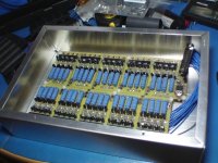
I am basicaly using the Gary-Fechter BMS desing but with a 24s and 5 more extension board ( 4 x 4s) + (1 x 24s)

As i discussed with Fechter and Camlight i also replaced the original N75F mosfet with 3 x FDP2532 of 150VDC rating. so using 3 mosfet in parallel, they should share the current and stay below theie max continuous current tolerance with a great tolerance margin.

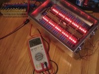
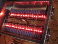
Since that BMs may dissipate alot of heat i've installed it in a large aluminum box with cooling fan.
When the 40 blue 5W resistors will be shunting the all cells at the end of charge, they will dissipate around 1.8W each... it's 72Watts of heat!.. The little 3W fan will be just enough to cooldown the BMS.

I think also that the EMI potential problem that Jack at www.EVTV.ME mentioned that may cause eratic bms measurement because of the voltage spike induced in the bms wires must be considered.
For that i think that instaling the 40s BMS in an aluminum box and by shilding the balance wires may help for that.
My friend said that they already measured the EMI for the vehicul safety approaval and they noticed that the most EMi they measured was coming from the DC-DC and not from the motor or the controller. it's an interetig fact!

Anyway, the BMS and battery will be located in the trunk so it's already shilded by the car frame.

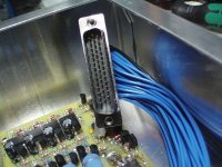
I also use some DB44 connector ( similar to the DB25) but with 3 row of pins for a total of 44 pins.
I'll also use some resetable fuse that will be connected between the battery and the balance wire.

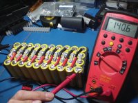
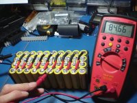
I also built a miniature 40s Battery using 40x A123 cells ( 18650 1.1Ah) to test it ( but i'll use only 5A of charging current when using them)

THIS SMALL PACK CAN DELIVER 132VDC at 60A burst!

Here is some pictures for you
 

Attachments

  • CAM_0090.JPG
    CAM_0090.JPG
    96.2 KB · Views: 3,433
  • CAM_0092.JPG
    CAM_0092.JPG
    96.8 KB · Views: 3,428
  • CAM_0094.JPG
    CAM_0094.JPG
    93.4 KB · Views: 3,428
  • CAM_0095.JPG
    CAM_0095.JPG
    89.4 KB · Views: 3,428
Nice looking BMS, Doc!

But according to Jack Rickard's blog at EVTV, you might not want to use a BMS with a balancing function at all! He seems to be claiming that an initial low voltage balance of the cells is better than balancing them close to their high voltage cutoff as we do. The low voltage balancing helps all the cells fall off closely together as the pack approaches it's low voltage cutoff point, minimizing the chances that the weakest cell drops too low and gets damaged. This is an interesting idea.

But this guy is also driving around an EV with large expensive LiFePO4 cells, but using no cell level LVC!!! No wonder he was killing cells when he was using a balancing charger... :roll:
 
Wow, this looks nice! Will you bypass the BMS while discharging?

What do you think, could this BMS be modified by adding more MOSFET-s to balance a 100cell - 320V car batt pack?

I would bypass it for discharge
 
ZapPat said:
Nice looking BMS, Doc!

But according to Jack Rickard's blog at EVTV, you might not want to use a BMS with a balancing function at all! He seems to be claiming that an initial low voltage balance of the cells is better than balancing them close to their high voltage cutoff as we do. The low voltage balancing helps all the cells fall off closely together as the pack approaches it's low voltage cutoff point, minimizing the chances that the weakest cell drops too low and gets damaged. This is an interesting idea.

But this guy is also driving around an EV with large expensive LiFePO4 cells, but using no cell level LVC!!! No wonder he was killing cells when he was using a balancing charger... :roll:

Zapat, i've followed this debate about balancing at the top or at the bottom. This guy is nice qith his episodes that explain EV on youtube and i appreciate the time he spent for doing that.

BUT.. I dont agree with him about balancing at the bottom. I think he forgot something crucial about property of cells.

The internal resistance variation over the discharge curve!

In fact, cells can have variation of internal resistance from one to another will heat differently when arriving to the LVC.

When this occur, they will heat differently.. some will have higher internal resistance and will heat more and some less..

That difference just can't help keep the balancing of all cells. Hest is energy loss during discharge..

AND.. is is a fact that lithium cells tend to have internal resistance that increase alot at end of discharge..

that make cell energy loss higher and higher variation form one cell to another.

I explained that in details in that thundersky cell thread:

http://endless-sphere.com/forums/viewtopic.php?f=14&t=14223&hilit=jack&start=15

Doc
 
CroDriver said:
Wow, this looks nice! Will you bypass the BMS while discharging?

What do you think, could this BMS be modified by adding more MOSFET-s to balance a 100cell - 320V car batt pack?

I would bypass it for discharge

That BMS have a mosfet ONLY to control the current flow from the charger.. not to the discharge lead.

i'll install two more mosfet to allow a zivan cahrger of 15A continuous ( each should get around 5A)

The discharge control for the LVC work by sending a signal to the motor controller to cut the throttle instead of cutting the entire juice from the cells.. it's cheaper and smarter. otherwise if you cut the main power as one cell go to the LVC, the entier electrical devices connected to the battery will cut.. and you dont want that. since the motor is the major power consumption cuting it thru the controller is ok... so the devices that use less juice can still be powered by the cells.

Yes, acording to Fechter and Gary, this BMS desing can take many more cells chanels

Doc
 
you quebecois are NUTs . i love it .

at the moment im really wishing my french teacher had not been a dutch guy with a thick accent as when id come home and try to talk french with my mom
(last name Guillou, french canadian from manitoba) she would look at me like i was speaking in tongues. Then i could have a nice conversation with you in your language, sadly i gave up on it when my mom kept laughing at my pronunciation. passed french 11 but its all gone now. désolé doc. (had to google that to make sure i still had it right)

not gonna happen tomorrow but between you and meth im gonna have to get my hands on a hub motor come spring and see what happens.

thats some nice looking work there
garder en s'amusant (that was all google) :mrgreen:
 
Comming back to the original subject hehe enoob.... :wink:

Today I finished assembling the two BMS board and all balance connectors and installed the two fans to push the heat outside the case.

Every of the 40 shunt work fine.

I did a mistake that i needed to correct :roll: ... The wire connected to the shunt from no21 to 40 was all wired reverse... 21 to 40 and 40 to 21... :lol:

All wire lenght was also pre calculated... :roll: .. I rewired everything and that work fine now.

Tomorrow i'll work on the LVC, mosfet HV upgrade and hope i'll be able to test using the mosfet that control the charger cut.

Here is some picture of the illuminated shunts:
 

Attachments

  • CAM_0124.JPG
    CAM_0124.JPG
    93 KB · Views: 3,067
  • CAM_0126.JPG
    CAM_0126.JPG
    85.3 KB · Views: 3,070
  • CAM_0127.JPG
    CAM_0127.JPG
    87.6 KB · Views: 3,069
now at 30 images per sec! 8)

Shunt test fonction.

Each of the 40 channels start shunt at 3.7V

[youtube]-yMgWl2xF2Y[/youtube]
Doc
 
Testing the LVC function.

It successfully at 2.1V for any of the 40 channels.

I replaced the controller and throttle hall sensor input by a mosfet trigged by the ebrake output.

[youtube]SwQ4OpxNrcE[/youtube]
 
Hi doc ! the last video its great ! this bms act like a cut off ? my speed controller from my rc plane work like this .

can i use theses bms for a ebike battery pack?

Belle job Doc !!, je voir sa en personne un moment donner :D
 
lifepo4ever said:
Hi doc ! the last video its great ! this bms act like a cut off ? my speed controller from my rc plane work like this .

can i use theses bms for a ebike battery pack?

Belle job Doc !!, je voir sa en personne un moment donner :D

Hi!!

Yes, these BMS awas first designed for ebike use.. but many Emotorcycle or schooter and Ecar now use them.

Doc
 
Back
Top