• Howdy! we're looking for donations to finish custom knowledgebase software for this forum. Please see our Funding drive thread

How To Ice Up Your Motor? (Cooling Ideas)

Again... you are still wrong here.

:arrow: Look up "forced convection".

You can effectively magnify the "apparent" surface area by forcing air over the top of a flat plate surface. Heat exchangers are designed using these principles. The movement of air inside the motor makes the heat transfer increase compared to still air.

It's like on a race car, they can get much better cooling if they shape the air intakes "just right" to get the maximum flow through the radiator. The faster the flow of air past the metal the faster the heat exchange.
 
Not Easy

I'm NOT saying that it's easy to predict the way air flows inside an electric motor. This link points to someone that seems to address the complexity: (it's actually a pdf)

http://www.cedrat.com/software/motor-cad/pdf/motorcad_IAS_2002_Digest.pdf

http://64.233.167.104/search?q=cache:eahEp0AaSEoJ:www.cedrat.com/software/motor-cad/pdf/motorcad_IAS_2002_Digest.pdf+forced+convection+electric+motor&hl=en&ct=clnk&cd=10&gl=us

End winding cooling

This area of machine cooling is renowned as being one of the most difficult to predict accurately. This is because the fluid flow (air in most cases) in the end space region of an electric motor is usually much more complex than that for flow over its outer surfaces. The flow depends on many factors including the shape and length of the end winding, added fanning effects due to wafters and salient poles, the surface finish of the end sections of the rotor and turbulence. Not withstanding the complexity, several authors have studied the cooling of internal surfaces in the vicinity of the end-winding. In the majority of cases they propose the use of a formulation of the form h = k1 x [1 + k2 vel **k3], where h = heattransfer coefficient (W/m2/C); k1, k2, k3 = curve fit coefficients and vel = local fluidvelocity (m/s). The k1 x 1 term accounts for natural convection and the k1 x k2 x vel **k3 term accounts for the added forced convection due to rotation. Fig 6 compares published correlations for end-space cooling, where relatively good correspondence is shown for such acomplex phenomena. In the main paper test and CFD will be used to develop rules for predicting the local velocity required in end-space convection calculation formulation. The relative accuracy of the windings temperature prediction and the use of such a simple formulation will also be discussed.

Airgap heat transfer

The traditional method for accounting for heat transfer across airgaps in electrical machines isto use the dimensionless algorithms developed from testing on concentric rotating cylinders.The main problem with such formulations is that the slot opening and in extreme cases salient poles make the use of smooth airgap cylinder data non valid. In the main paper the inaccuracies that can be expected by using a smooth airgap formulation will be discussed. Also, more recent work that has been carried out on developing formulations to account for slot-opening and salient poles will be reviewed.
 
yawn_201.gif
 
How about someone just gets some nichrome wire and makes a coil inside the motor casing (everything else taken out) to see whether ice or air is more effective. I don't know about you but this thread is becoming very futile very fast. Safe is set on the ice "kissing" technique, so all that's left to do now is implement it.
 
Words From the Pros

Okay... it was hard to find good information on this, but I think I've finally found a solid and professional paper (pdf) that covers the topic. Everything I've been intuitively seeing is valid... "Ice Kissing" is validated by experiment.

https://www.ee.lut.fi/fi/opi/kurssit/Sa2720400/9%20heat%20transfer.pdf

Forced convection increases the convective heat transfer coefficient even 5–6 times higher depending on the air velocity.

The maximum rate at which heat can be transferred by natural convection and radiation from a surface of an electric machine, with a temperature rise of 40 °C, is approximately 800 W/m2. With forced convection, the density of the heat flow can reach 3000 W/m2, and with direct liquid cooling, 6000 W/m2. Motors that generate more heat power than can be removed at this rate have to store the excess heat in their thermal mass. This is quite an acceptable method for a short time.

The above values limit the heat generated per unit volume to approximately 12 kW/m3 for natural convection, and to 300 kW/m3 for metallic conduction, to 400 kW/m3 for forced convection, and to 600 kW/m3 for direct liquid cooling.


So hopefully this ends any uncertainty... liquid cooling of the motor shell (what they are talking about) is the best way to cool your motor. Ice just makes it even better.

:arrow: Not only that but my "wild guess" about radiation as being a significant factor was also correct:


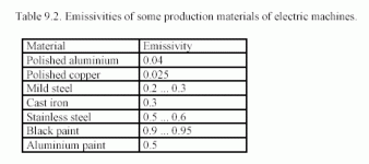
Therefore, we can see that heat transfer by radiation is of considerable significance in the total heat transfer of an electric machine. Table 9.2 lists typical emissivities of some production materials of electric machines.

Just download the pdf... it answers all the questions. :)

Notice also that the 400 kW/m3 verses 600 kW/m3 is the same general ratio that I was figuring. The "Ice Kissing" solution should be about 50% better than a blower. (and you don't need a battery to make it work!)
 
Direct fluid cooling would mean fluid on the coils.

Forced convection is the same as forced air, only you are re-using the air. Warmer air (50C).

:roll:
 
TylerDurden said:
Direct fluid cooling would mean fluid on the coils.

No... that would be "silly". :lol:

(imagine how hard the rotor would have to work spinning in a fluid :roll: )

:arrow: Did you even bother to download the pdf?

They do a good job talking about INDUSTRIAL electric motors. I've even seen cross sectional pictures of the motors and they have water cooling vents inside the shell just like a car motor does for it's water cooling.

:arrow: The fact of the matter is that the ranking goes something like this: (from least cooling to most)

1. Radiant cooling of the shell alone. (stock motor)

2. Forced Air cooling through the insides of the motor. (blower)

3. Water cooling. (of the shell)

4. Ice cooling (would be slightly better)


"Totally Enclosed, Water Cooled"

http://www.oddparts.com/acsi/defines/tewc.htm

Face it... yet again I'm right and you are wrong... but what the heck, the concept of "Fight Club" isn't to win, but just to fight, so in that sense we're all winners anyway. :wink:
 
http://www.fuelcellmarkets.com/green_motorsport/products_and_services/3,1,388,17,12958.html

The GMS High performance AC water cooled motor

The new unit is to be called the GMS M1 and boasts incredible performance characteristics. The AC water cooled 48 volt high performance, high frequency motor is capable of pulling 870 amps peak. The new motor delivers its power in a very different way from the conventional DC motor, being comparable to our former 40 kW DC motor used in our older performance kart which set speed records at Rockingham race track in the UK. The performance is obtained by an impressive water cooling system and efficient windings. The motor’s cooling system is unique and is the first of it’s kind whereby the water cooling jacket is totally seamless. The new water cooled motor is designed for high performance and has been engineered to the highest quality. The motor design is compact due to it’s water cooling, highly efficient windings and the benefits of being brushless and totally sealed from the elements making it durable and robust. This makes it suitable for almost any application, from electric cars, to water craft or any other high performance application where keeping costs low is of importance. The technology will be proven in motorsport, the most demanding environment known for its automotive research and development. The AC motor is a joint effort of Green MotorSport technology partners, with over 40 years’ combined expertise in the electric motor business.


GMS%20AC%20Motorsm.JPG
wisper_greenmotorsport.jpg
hillclimbproject_greenmotor.jpg


http://www.fuelcellmarkets.com/green_motorsport/news_and_information/3,1,388,1,14752.html

_GMS0049hires_BWCsm.JPG
 
The fluid cooling is for AC motors.

In DC motors and vector-controlled AC motors, an additional cooling fan is employed, since these motors are usually operated for a long period of time with a high torque and a low rotation speed. Since in DC machines most of the heat is generated in the rotor, a good internal cooling flow is required. This applies partly to induction motors, too. In synchronous machines and reluctance machines, most of the heat is generated in the stator windings, and therefore their cooling is somewhat easier than the cooling of DC machines and induction machines.

Final paragraph:

For a through-cooled construction, in theory, it is possible to determine the required mass flow qm'' = dm/dt [kg/s] with the specific heat capacity cp of air by the following equation
q''m Φth = cpΔTq . The specific heat capacity cp of air in constant pressure is approx. cp = 1 kJ/(kgK). A through-cooled construction is a quite an advantageous cooling method.
 
"If rated torque is required at low rotation speed, a shaft-mounted blower may not be able to produce sufficient forced convection to cool the motor."

And it goes on with:

"In DC motors and vector-controlled AC motors..."

What they are talking about is that in the typical PWM controller you have that same thing we were talking about before at low rpm where you can get good torque at low rpm (because of current multiplication) and so one might be tempted to run the motor at low speed and build up a lot of heat very quickly. The DC motor (because of it's design) can't transfer heat without a lot of spinning going on inside. (remember from before we learned that the transfer rate increases by 5 or 6 times or more with high rpm)

So this does make one think...

:arrow: You CAN get the full cooling effect AT HIGH RPM.

:arrow: But you CAN'T get the full cooling effect (of water cooling) at low rpm.

So this makes my design correct.

If you use Armature (motor) Current Limiting it eliminates most of the heat (and torque) at low rpm. But with ACL you still get "normal" heat at high rpm where the peak power is located.

:arrow: In effect the unique solution I'm going down (ACL, Ice Kissing, Gears) will exploit all the best qualities that can be exploited.

:idea: You've made a good point.

So you're not a total loser... :lol:
 
A Simple Slogan

"A DC motor that does not spin does not cool."

Ice Kissing will only work when the motor is spinning at high rpm. (because that's the only way to transfer the heat from the rotor to the shell through forced air convection) Heavy use of low end torque at low rpm would lower the heat transfer rate at the very time that the heat would be building up. The moral of the story might be that for the conventional fixed gear (hub motor), standard controller bike the blower is probably the safer cooling method. (because the blower can cool the motor when the motor isn't spinning very fast)
 
You're taking snippets out of context. :roll:

Full-graph:
"If rated torque is required at low rotation speed, a shaft-mounted blower may not be able to produce sufficient forced convection to cool the motor. In DC motors and vector-controlled AC motors, an additional cooling fan is employed, since these motors are usually operated for a long period of time with a high torque and a low rotation speed. Since in DC machines most of the heat is generated in the rotor, a good internal cooling flow is required. This applies partly to induction motors, too. In synchronous machines and reluctance machines, most of the heat is generated in the stator windings, and therefore their cooling is somewhat easier than the cooling of DC machines and induction machines."

Forced-air cooling, peaches.

But it's your motor: toast it, boil it or steam it any way you like. You'll have a nice cold drink of water before you pedal or push your way back home.

:p
 
What it Will Look Like

This is roughly how I see the cooling behaving. The Battery Current Limited motor produces huge levels of heat (and torque) at low rpm where the Ice Kissing does NOT work very well. At high rpm the rate of cooling increases and beyond peak power the rate of cooling is very high. At the highest rpm the Ice Kissing is very effective.

Using Gears, Armature Current Limiting and Ice Kissing would produce an extremely potent combination of advantageous physical properties.

Without Gears and Armature Current Limiting the Ice Kissing will still work, but you might find yourself on a long hillclimb at low rpm and this would be a situation where the Ice Kissing would not work very well.

:arrow: So it's kind of an "all or nothing" deal here. If you go down the "Ice Kissing" route you need to exploit the other things (ACL, Gears) in order to get it's full effect. For a fixed geared bike you might as well stick to a blower.
 

Attachments

  • cooling of BCL vs ACL.gif
    cooling of BCL vs ACL.gif
    12.3 KB · Views: 2,744
TylerDurden said:
...since these motors are usually operated for a long period of time with a high torque and a low rotation speed.

It's all about rotation speed.

"A DC motor that does not spin does not cool."
 
It's 38 degrees outside right now. :(

Trust me, if I could ride I would... (I'm looking forward to spring)
 
Boosting Radiant Heat Transfer

One thing that I noticed in one of those pdf files is that you can increase the emissivity of your rotor by simply painting it black. What a "no brainer" upgrade. I think I'd probably want to get some paint that was designed for exhaust pipes so that I wouldn't have to worry about it somehow catching fire on me.

:arrow: Radiant heat isn't a huge thing, but if I can increase the cooling by another 10 - 20 watts just by adding some paint, then why not?
 
I'd look for automotive radiator paint specifically. That emissivity gain may be canceled out by the thickness of the paint layer acting as insulation. Looks like another task for super temp probe testing man! Whoever uh, wants to be him.
 
785556.gif


High heat and radiator paint produces a fast and durable flat finish. This heat-resistant paint restores, protects, and beautifies metal surfaces subjected to high temperatures. Withstands 1200 F. temperatures. Durable finish protects against rust. Great for use on radiators, grill works, automotive parts, pot belly stoves, and fireplace equipment.

As long as the thickness was moderate I'd guess that it would behave like the table suggests it behaves. (see below)

Just about anything is better than laminations of steel that are kind of shiny. (0.2 - 0.3)

I would probably not actually spray it on, but spray it into a puddle and then carefully paint it onto the rotor where it faces the shell. It's only really going to matter for that area between the rotor and shell. (the sides aren't going to matter much)

Using the calculator:

http://hyperphysics.phy-astr.gsu.edu/hbase/thermo/stefan.html#c3

Use 0 C, 100 C, 0.0096 m^2 and first use 0.3 and you get:

22.6 watts

Change the emissivity value to 0.9 and you get:

67.7 watts

...for a net gain in radiant cooling of 45.1 watts. (not bad for some paint :) )

Also, radiant heat doesn't require that the motor spins, so you get a little motor cooling as a baseline at lower rpm. The big advantage of a blower is that it's a CONSTANT rate of cooling no matter what rpm you are at.

:arrow: There's nothing that says you can't do external and internal cooling at the same time...
 

Attachments

  • emissivity table.gif
    emissivity table.gif
    7.3 KB · Views: 2,710
monster said:
what about oil cooling is that possible with this application?

:arrow: Since you are really just cooling the shell you could do anything.

If you really wanted to go overboard you could use something like liquid nitrogen and get the shell so cold that the resistance in the motor would really drop. In my spreadsheet model I put in -100 C (just for fun) and get a top speed of 56 mph! (which is extreme for a little 350 watt motor) At normal air temperature the top speed is more like 45 mph with all the other tricks I'm planning to do. (which is already pretty good)
 
Some Thoughts About Cooling and Resistance

One of the interesting things about cooling your motor is the way it effects your overall motor performance profile. It appears that the efficiency curve shape of the motor DOESN'T change, but the current does:

Current = Voltage / Resistance

...so the effect of dropping the resistance is to increase the current and that means you can get more torque and when you combine that with rpm more power.

:arrow: It's weird...

You are in effect getting "free" power if you lower the resistance. Your range would be better if you backed off the throttle a little, but if you kept the throttle wide open you would have nearly the same result.

Resistance is like "time"... if you lower the resistance then everything happens in "fast forward" mode and the current flows easily. If you raise the temperature and create more resistance then everything slows down and eventually the motor can't deliver the power fast enough to do the things you want it to do. (as the temperature goes up the power goes down)

On my SLA battery bike the battery slows down due to it's own internal resistance. The irony of my SLA battery is that when it's hot outside and the motors resistance is INCREASING (because of the heat) the battery is doing the opposite and it's resistance is DECREASING making it work better. When it's cold everything reverses and the cold weather makes my motor power INCREASE and my batteries ability to deliver power DECREASE.

Electricity can be weird... :?
 
You need some kind of heat pump to make both happy. Too bad about the thermoelectric peltier junctions being so damned inefficient.
 
safe said:
Some Thoughts About Cooling and Resistance

One of the interesting things about cooling your motor is the way it effects your overall motor performance profile. It appears that the efficiency curve shape of the motor DOESN'T change, but the current does:

Current = Voltage / Resistance


The predominant loss in the motor is due to resistance in the copper. If you lower the resistance, the losses will be porportionally less.
This means if you lower the resistance, the efficiency will increase.

Liquid nitrogen is not such a crazy idea. The next step is to just get superconducting wire. Then you would have zero resistance loss and zero heating due to it. If no heat was generated by the windings, keeping them cold wouldn't be so hard. :wink:

Of course you'd have to deal with brittle metal and cryogenic bearings, but those problems are easily solveable.
 
fechter said:
This means if you lower the resistance, the efficiency will increase.

When I first looked at that I suspected that it didn't look right and I'm glad you brought it up. Seems like the peak efficiency doesn't seem to change much (if at all), but the rest of the curve does and so you can plot the moving location of the peak power efficiency relative to temperature.

:idea: Any idea why the peak doesn't seem to change and yet the main part of the curve does?
 

Attachments

  • Efficiency vs Temp(C) @ Peak Power.gif
    Efficiency vs Temp(C) @ Peak Power.gif
    12.4 KB · Views: 2,644
Back
Top