Kingfish
100 MW
Goal:
I want an inexpensive charger that is Constant-Current (CC) and Constant-Voltage (CV) for my 15-to-20 cell LiPo configurations, and I want it to charge quickly.
Greetings -
Initially I had thought to append to my earlier topic: Configuring a Meanwell 84V charger, but after my road trip experience my wish is to provide a better solution based upon a more thorough understanding.
ADDENDUM: Related thread - Review: Meanwell HRP-600 Series
Last winter I bought three SP-320-48 genuine Meanwells off of eBay for < $35 each for the specific purpose of quick charging. It turned out that the SP units have a problem with CC or being modified to do so; whatever. The new theory suggests that if you purchase an older S- unit and place it in series you can make your grand arrangement CC. I bought an S-350-27 to complement my array for just that purpose.
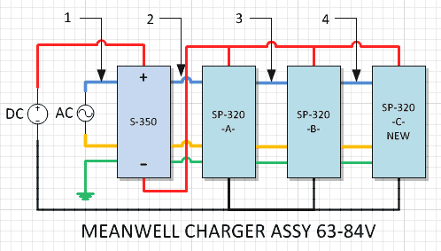
With two SP-320-48 units in parallel, followed by one S-350-27 unit in series this will create a 75V setup which can be easily trimmed up to create an 84V charger. The trick was to balance the -48 units to the same voltage first, then trim to the final voltage with the -27 unit.
In the process of trying to leave for my trip the 74V-controller didn’t work out. My ass was in a bind, and I was just damn lucky I could de-tune the Meanwell setup to support 63V.
Creating the 63 Volt Charger:
Put the S- unit on top (the reason will be apparent very shortly). Tune the voltage down on SP-320-48 units individually first through the SVR POT collocated next to the LED on the rear panel; one unit will be able to go a little lower than the other so you will need to match them to the lowest common setting (mine are set to about 38.5V). Hook up the S-350-27 unit in series and then tune it down as low as it will go which should render the assembly down to about 63V; it is a tiny bit high for 15S LiPo but good enough for use with a BMS.
Shopping thoughts:
Though the -48 units are easy to find, the -27 model took some searching; it wasn’t my first choice but now I wouldn’t trade it away.
Flogging the Thermistor Mod:
There are pages of information given to modifying the Thermistor to modulate the fan on the S- units: Some say remove and short the contacts, other say put a POT parallel. I did the POT thang; it’s hokey but it works. Here’s what you get:
Flogging the Current Mod:
This initial mod did not work on the S- unit: Following suggestions I put a 2k resistor in parallel with the R33 to cut down on its’ value to create constant current, however the mod had no effect. In the field my 15S9P battery pack still took 9 to 10 hours to charge and left me quite frustrated: The output of the assembly is 2x320 + 350 watts which should provide close to a kW during charge. However due to the hiccup mode I was lucky to get 500W. A strong angst towards resolving this mystery ensued
Shortly upon my return home I ripped out the S-530-27 circuit board, opened up Visio, and began to reverse the circuit.
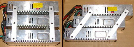
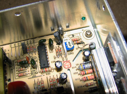
Top-side of S-350 PCB. SVR1 is at the top-left, and SVR2 is at the top-right. The disconnected R33 mod is still visable.
In the center of the PCB you can see the 1k POT mod across the Thermistor.
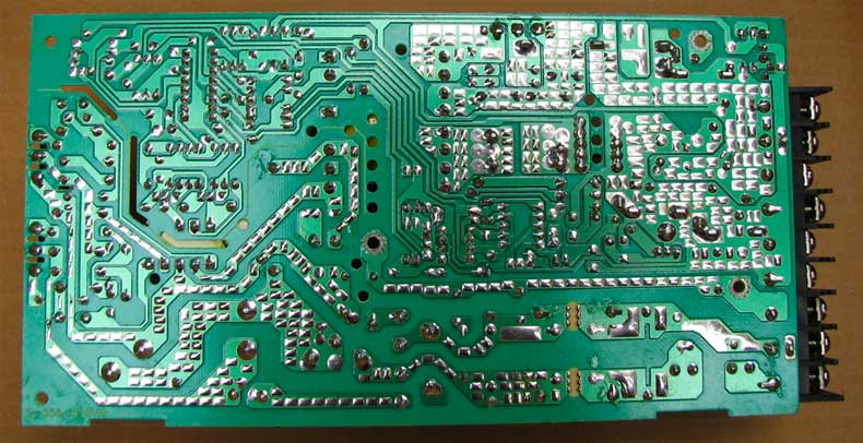
Back-side of S-350 PCB.
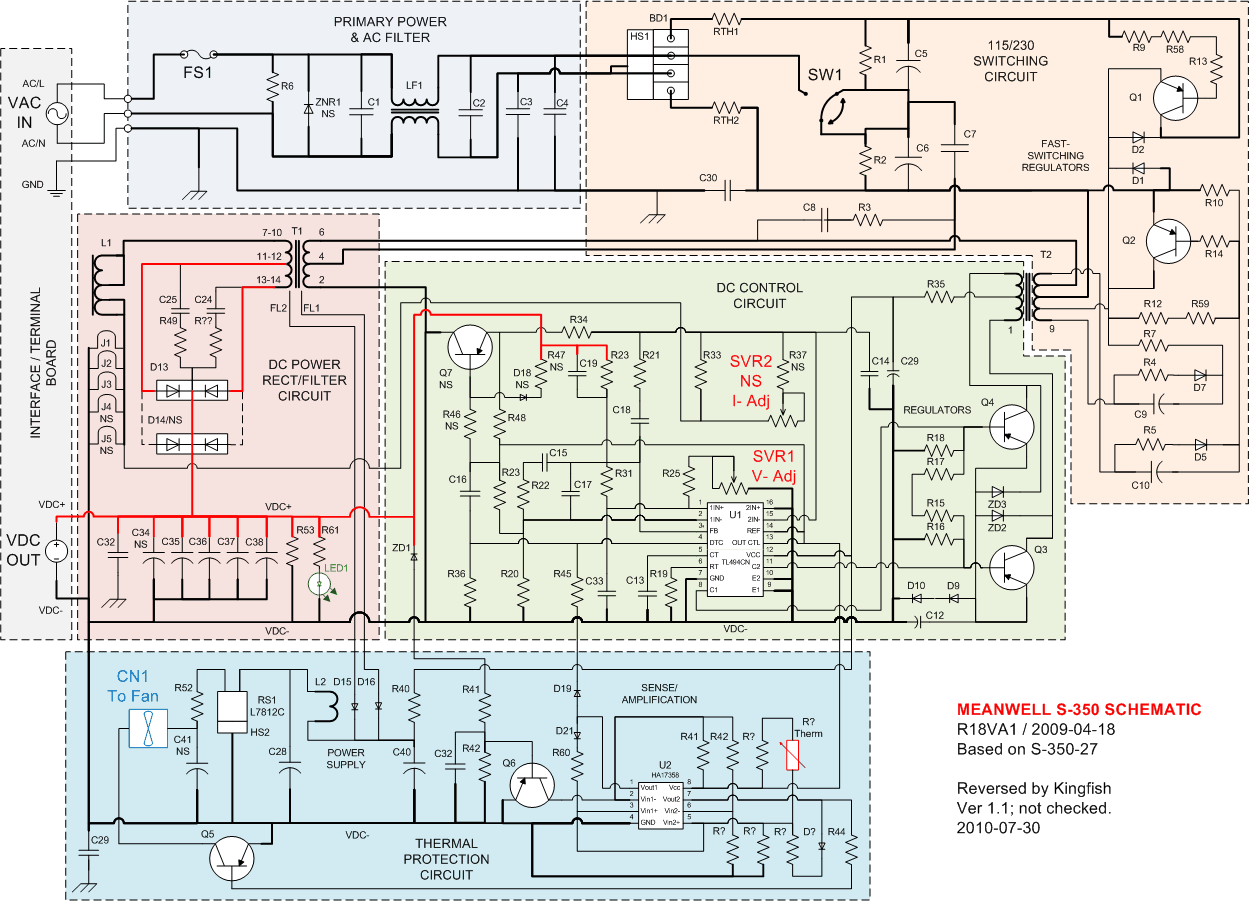
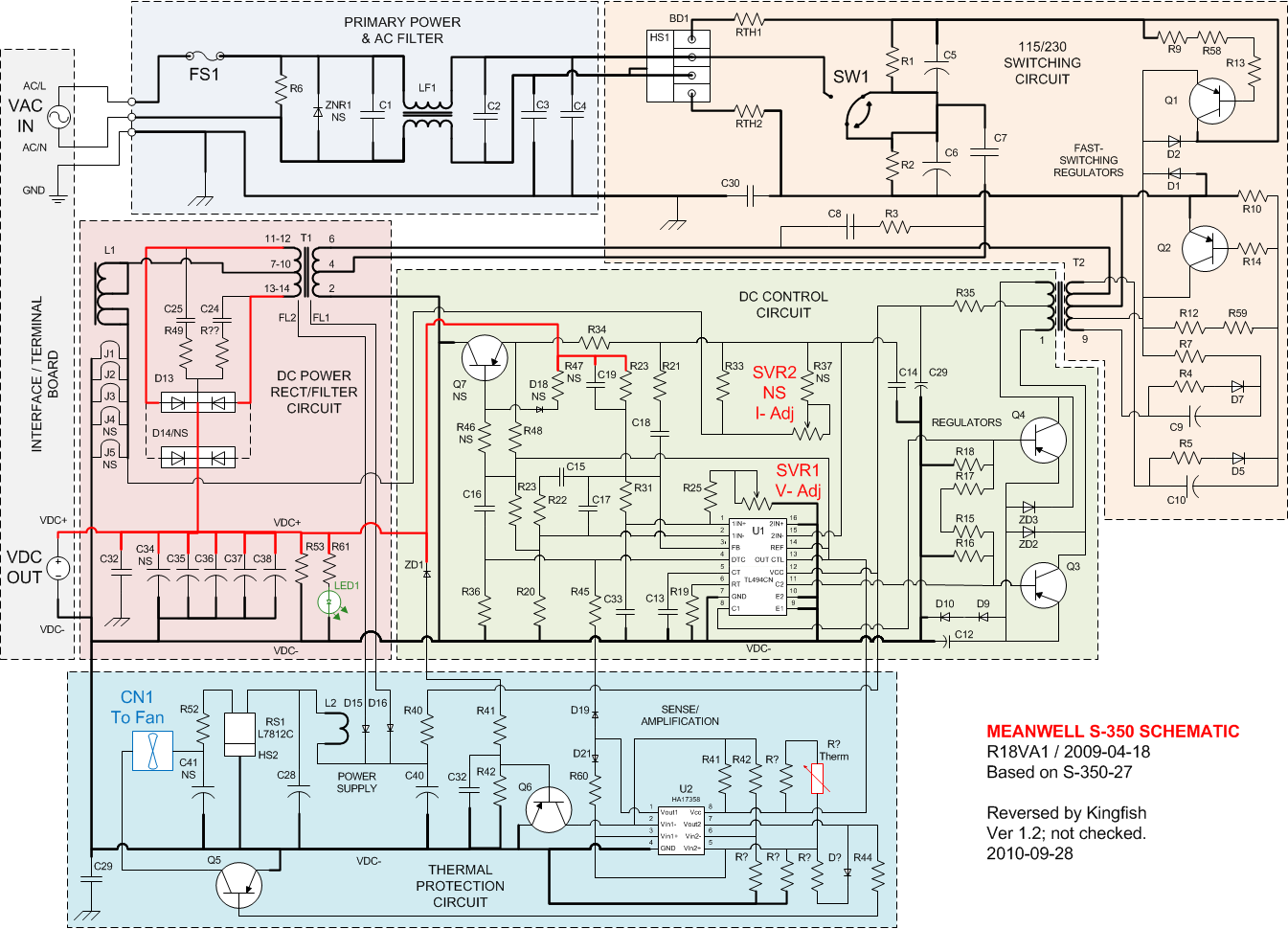
Allow me to state that Visio is a flimsy bit of software for creating schematics; I miss the days of OrCAD, PADS, heck even AutoCAD could do a better job. But it’s the tool that I had on hand. So without further ado, here is the schematic for the S-350 series boards.

Click on the image to view the full size.
Interestingly one board serves all the models within this wattage range. Please note the board revision as yours may be older or newer. I can’t speak for clone boards; I bought the genuine Meanwell article, genuinely made in China.
 With schematic in hand I now had a map to the device: The first thing I noticed is that there production adjustments to this design; little things give it away such as the ordering of resistor numbers and culling of parts (NS). It’s also possible that there was a cost-reduction performed, though clearly some pieces belong to other models (D14 lends a clue). One item not installed on my unit is the SVR2 and R37 which affects directly how much current the unit produces. Maybe early versions or models didn’t use R33; it’s all speculative. Regardless, after reviewing the schematic and spec sheets for the primary components (U1, U2, RS1, and Q1/2) I set about to put SVR2 back in.
Biked down to Radio Shack and for < $1.75 I picked up a 1k POT. The previous mod for R33 was removed (one or more resistors in parallel). Instinctively I placed a jumper across the empty R37 slot. Then I soldered the 1k POT to the SVR2 location and then made sure the POT was at max ohms which gave a reading across R33 initially at 621 ohms down to about 370. Reassembled the whole unit sans cover, connected the assembly to my commuter battery pack (15S3P drained to about 55.2V), and then plugged it in. Within moments of warming up the Meanwell array was back to pulse-charging: Effectively no change to previous behavior.
SRV2 installed and Jumper placed across R37.
With a thin screwdriver I carefully, very slowly turned SVR2 backwards, reducing the resistance – and almost immediately I began to audibly hear the durations between the pulses grow shorter and shorter, suggesting that the charging was going faster and faster. Using the CA to monitor the present voltage confirmed this point. Cautiously hesitant at first, I proceeded until the unit stopped pulsing altogether. With the CA, I could actually see the battery rising a tenth of a volt at a time over a span of a couple of minutes; it was quite exciting! I triple-checked the present trim-spot and I felt the units for excessive heat (none beyond mildly warm). Satisfied, I made dinner whilst the assembly charged-away.
Within one hour my pack was completely charged. Now I gotta tell you that with my original charger it would have taken 5-6 hours, and with this charging assembly before this moment it would have taken nearly 3 hours. Problem resolved
FWIW, measuring across R33 with the SVR2 POT in the present setting, the ohms read close to zero.
Musings:
I’d really like to understand why these units were adjusted to pulse-current and not to provide constant current out of the box. Or is it simply the way we employ the device that if goofs with sense circuitry?
Caveats:
When the charger is going full-blast, the two SP-320-48 fans are loud and going full speed. I can deal with that 8)
Schematic Warrantee:
The diagram provided has not been cross-checked; being human I am certain that there are errors. If someone would be so kind as to check me I would be truly grateful. Also, there is no plan to create a parts list, however if you forward the values for components then I will add them. Lastly, I apologize for the lameness of some of the symbols I used; Visio falls short on electrical shapes and I just did the best of what I could with what I had. All the transistors are presumed to be TO92A and PNP; they need to be checked. Jumpers are not shown on the schematic (there wasn’t a convenient Visio symbol available).
Conclusions:
Finally, I think I achieved what I paid for :wink: 
Worries:
None mate. Between this and dinner, I found myself sated... for the moment
Onward, to the next challenge.
Enjoy, KF
I want an inexpensive charger that is Constant-Current (CC) and Constant-Voltage (CV) for my 15-to-20 cell LiPo configurations, and I want it to charge quickly.
Greetings -
Initially I had thought to append to my earlier topic: Configuring a Meanwell 84V charger, but after my road trip experience my wish is to provide a better solution based upon a more thorough understanding.
ADDENDUM: Related thread - Review: Meanwell HRP-600 Series
Last winter I bought three SP-320-48 genuine Meanwells off of eBay for < $35 each for the specific purpose of quick charging. It turned out that the SP units have a problem with CC or being modified to do so; whatever. The new theory suggests that if you purchase an older S- unit and place it in series you can make your grand arrangement CC. I bought an S-350-27 to complement my array for just that purpose.
With two SP-320-48 units in parallel, followed by one S-350-27 unit in series this will create a 75V setup which can be easily trimmed up to create an 84V charger. The trick was to balance the -48 units to the same voltage first, then trim to the final voltage with the -27 unit.
In the process of trying to leave for my trip the 74V-controller didn’t work out.
My ass was in a bind, and I was just damn lucky I could de-tune the Meanwell setup to support 63V.Creating the 63 Volt Charger:
Put the S- unit on top (the reason will be apparent very shortly). Tune the voltage down on SP-320-48 units individually first through the SVR POT collocated next to the LED on the rear panel; one unit will be able to go a little lower than the other so you will need to match them to the lowest common setting (mine are set to about 38.5V). Hook up the S-350-27 unit in series and then tune it down as low as it will go which should render the assembly down to about 63V; it is a tiny bit high for 15S LiPo but good enough for use with a BMS.
Shopping thoughts:
Though the -48 units are easy to find, the -27 model took some searching; it wasn’t my first choice but now I wouldn’t trade it away.
Flogging the Thermistor Mod:
There are pages of information given to modifying the Thermistor to modulate the fan on the S- units: Some say remove and short the contacts, other say put a POT parallel. I did the POT thang; it’s hokey but it works. Here’s what you get:
- Without the mod, when this unit gets hot and turns the fan on to cool down, it will drop the output voltage in half - which IMO it is a terrible design. Adjusting SVR1 to compensate did not change the output; my S-350-27 unit was fixed at 13V.
- With the mod in place, wait till the unit gets hot and the fan begins to spin. Adjust the 1K POT until the fan stops ~ whalla; end of problem!
- Or – you can elect to do what I did in the field which is to put the S- unit on the top of the stack and remove the lid when charging which effectively disconnects the fan. Done, no mod required, end of problem.
Flogging the Current Mod:
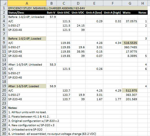
This initial mod did not work on the S- unit: Following suggestions I put a 2k resistor in parallel with the R33 to cut down on its’ value to create constant current, however the mod had no effect. In the field my 15S9P battery pack still took 9 to 10 hours to charge and left me quite frustrated: The output of the assembly is 2x320 + 350 watts which should provide close to a kW during charge. However due to the hiccup mode I was lucky to get 500W. A strong angst towards resolving this mystery ensued
Shortly upon my return home I ripped out the S-530-27 circuit board, opened up Visio, and began to reverse the circuit.
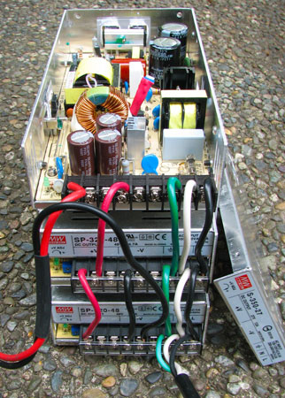
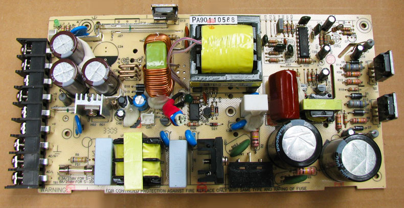
Top-side of S-350 PCB. SVR1 is at the top-left, and SVR2 is at the top-right. The disconnected R33 mod is still visable.
In the center of the PCB you can see the 1k POT mod across the Thermistor.
Back-side of S-350 PCB.
Allow me to state that Visio is a flimsy bit of software for creating schematics; I miss the days of OrCAD, PADS, heck even AutoCAD could do a better job. But it’s the tool that I had on hand. So without further ado, here is the schematic for the S-350 series boards.

Click on the image to view the full size.
Interestingly one board serves all the models within this wattage range. Please note the board revision as yours may be older or newer. I can’t speak for clone boards; I bought the genuine Meanwell article, genuinely made in China.
Biked down to Radio Shack and for < $1.75 I picked up a 1k POT. The previous mod for R33 was removed (one or more resistors in parallel). Instinctively I placed a jumper across the empty R37 slot. Then I soldered the 1k POT to the SVR2 location and then made sure the POT was at max ohms which gave a reading across R33 initially at 621 ohms down to about 370. Reassembled the whole unit sans cover, connected the assembly to my commuter battery pack (15S3P drained to about 55.2V), and then plugged it in. Within moments of warming up the Meanwell array was back to pulse-charging: Effectively no change to previous behavior.
SRV2 installed and Jumper placed across R37.
With a thin screwdriver I carefully, very slowly turned SVR2 backwards, reducing the resistance – and almost immediately I began to audibly hear the durations between the pulses grow shorter and shorter, suggesting that the charging was going faster and faster. Using the CA to monitor the present voltage confirmed this point. Cautiously hesitant at first, I proceeded until the unit stopped pulsing altogether. With the CA, I could actually see the battery rising a tenth of a volt at a time over a span of a couple of minutes; it was quite exciting! I triple-checked the present trim-spot and I felt the units for excessive heat (none beyond mildly warm). Satisfied, I made dinner whilst the assembly charged-away.
Within one hour my pack was completely charged. Now I gotta tell you that with my original charger it would have taken 5-6 hours, and with this charging assembly before this moment it would have taken nearly 3 hours. Problem resolved
FWIW, measuring across R33 with the SVR2 POT in the present setting, the ohms read close to zero.
Musings:
I’d really like to understand why these units were adjusted to pulse-current and not to provide constant current out of the box. Or is it simply the way we employ the device that if goofs with sense circuitry?
Caveats:
When the charger is going full-blast, the two SP-320-48 fans are loud and going full speed. I can deal with that 8)
Schematic Warrantee:
The diagram provided has not been cross-checked; being human I am certain that there are errors. If someone would be so kind as to check me I would be truly grateful. Also, there is no plan to create a parts list, however if you forward the values for components then I will add them. Lastly, I apologize for the lameness of some of the symbols I used; Visio falls short on electrical shapes and I just did the best of what I could with what I had. All the transistors are presumed to be TO92A and PNP; they need to be checked. Jumpers are not shown on the schematic (there wasn’t a convenient Visio symbol available).
Conclusions:
Finally, I think I achieved what I paid for :wink:
Worries:
None mate. Between this and dinner, I found myself sated... for the moment
Onward, to the next challenge.
Enjoy, KF