Matador
100 kW
- Joined
- Jun 29, 2016
- Messages
- 1,045
CONTEXT :
I have a BC168 6S Balance charger. The charger is great as it balance charges directly through the balance leads (no cell bleeding by resistor, all balancing is done by charging !). Technically, each cell can be charged to up to 8AMPS. At 4.2V, 6 channels at 8Amps each make 202 W of output power. The BC168 charger requires 300W (ideally 330W to make sure) in order to be used at it's fulled potential.
The thing is, as many chargers (for example the well known Imax B6 charger - 50W), you're left to choose your own power supply to feed the charger. My BC168 can be feed with 12-15Volts. My Imax B6 min can be fed with 11-18V. My BST900 boost converter can be fed with 8-60V IIRC.
THE FIND :
Though I'd share a find with you guy, thanks to Doctorbass for telling me about this great deal. I got this HP DPS-1200FB 1200W Server Power Supply for 30 dollars canadian off eBay. They are everywhere and for cheap. In USA, you can probably get them for 15 USD shipped. The 1200W rating is if the mains are 240V AC. With 110-120V AC, it outputs 900W which is more than enough for my needs. There is a lot of discussion about this PSU on RC forums and Youtube. Some people even show video tutorials on YouTube about how to put up 4 of these in series to get 48V with what they call "THE FLOAT MODIFICATION". This modification is apparently absolutely crucial (all but the first power supply need modification for grounding).
To make it work (otherwise, the PSU stays in Standby, with 0 Volts on the output), some people solder a 560 Ohms or 1kOhms resistor across pins 33 and pins 36. Others just put a jumper or a switch between these pins.
THE QUESTION :
I was wondering, what's the best resistor value to put between those pins ? Is it best to just put a jumper ? I could not find information about the best way to do it... What's the rational behind that resitor thing ? At one point, I was wondering, what's the function of all these pins on the PSU ???
Well, I finally found a detailed description about this PSU by someone who seems to work in the field of computer server engeneering... He explains every pin.
Though I'd share the link (a blog) with you guys. Here it is : http://colintd.blogspot.ca/2016/10/hacking-hp-common-slot-power-supplies.html#!/2016/10/hacking-hp-common-slot-power-supplies.html
In case the blog website disapears one day, here is the text in PDF version (archive for future reference if needed) : View attachment Hacking the HP DPS-1200FB A PSU.pdf
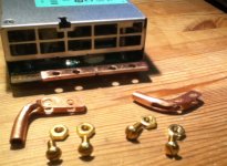
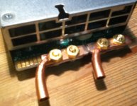
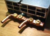
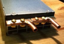
FINALLY, THE PICS (Here is my DPS-1200. I added some homemade copper contacts, and made holes in them for more ease of use - see last pic) :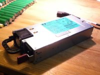 View attachment 3
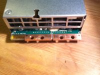 Would push 12V@75A (on 110-120 AC mains) or 12V@100A (on 200-240V AC mains), so I though It'd be best to have heavy duty copper contacts. I made them with 1/4 inch copperpipe that I flattened, open in on end with a dremel grinder disk tool. Also made multiple small holes to add even more solder inside. Made bigger holes for wire lugs to be bolted in.
View attachment 1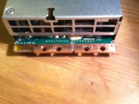
I have a BC168 6S Balance charger. The charger is great as it balance charges directly through the balance leads (no cell bleeding by resistor, all balancing is done by charging !). Technically, each cell can be charged to up to 8AMPS. At 4.2V, 6 channels at 8Amps each make 202 W of output power. The BC168 charger requires 300W (ideally 330W to make sure) in order to be used at it's fulled potential.
The thing is, as many chargers (for example the well known Imax B6 charger - 50W), you're left to choose your own power supply to feed the charger. My BC168 can be feed with 12-15Volts. My Imax B6 min can be fed with 11-18V. My BST900 boost converter can be fed with 8-60V IIRC.
THE FIND :
Though I'd share a find with you guy, thanks to Doctorbass for telling me about this great deal. I got this HP DPS-1200FB 1200W Server Power Supply for 30 dollars canadian off eBay. They are everywhere and for cheap. In USA, you can probably get them for 15 USD shipped. The 1200W rating is if the mains are 240V AC. With 110-120V AC, it outputs 900W which is more than enough for my needs. There is a lot of discussion about this PSU on RC forums and Youtube. Some people even show video tutorials on YouTube about how to put up 4 of these in series to get 48V with what they call "THE FLOAT MODIFICATION". This modification is apparently absolutely crucial (all but the first power supply need modification for grounding).
To make it work (otherwise, the PSU stays in Standby, with 0 Volts on the output), some people solder a 560 Ohms or 1kOhms resistor across pins 33 and pins 36. Others just put a jumper or a switch between these pins.
THE QUESTION :
I was wondering, what's the best resistor value to put between those pins ? Is it best to just put a jumper ? I could not find information about the best way to do it... What's the rational behind that resitor thing ? At one point, I was wondering, what's the function of all these pins on the PSU ???
Well, I finally found a detailed description about this PSU by someone who seems to work in the field of computer server engeneering... He explains every pin.
Though I'd share the link (a blog) with you guys. Here it is : http://colintd.blogspot.ca/2016/10/hacking-hp-common-slot-power-supplies.html#!/2016/10/hacking-hp-common-slot-power-supplies.html
In case the blog website disapears one day, here is the text in PDF version (archive for future reference if needed) : View attachment Hacking the HP DPS-1200FB A PSU.pdf
FINALLY, THE PICS (Here is my DPS-1200. I added some homemade copper contacts, and made holes in them for more ease of use - see last pic) :
 View attachment 3
 Would push 12V@75A (on 110-120 AC mains) or 12V@100A (on 200-240V AC mains), so I though It'd be best to have heavy duty copper contacts. I made them with 1/4 inch copperpipe that I flattened, open in on end with a dremel grinder disk tool. Also made multiple small holes to add even more solder inside. Made bigger holes for wire lugs to be bolted in.
View attachment 1


