Quantumflux
1 mW
I'm building an arduino controlled motorized platform.
So I have the following hub motor wheels (testing with these first) :
I've connected them up to a cheap brushless controller, but they don't work:

Specifically, I have the Motor Hall connector, the motor 3 phase line connectors connected, up, as well as the throttle connector wired to +5VDC, ground and a constant 4.15VDC voltage (full throttle?). I've tried not having the 4.15VDC connected. I've tried various options of jumpering electric door lock, etc.. The self learning / identify the switch cable connected after (or before) power on, but nothing happens with the motor. I've checked with my multimeter that I'm getting correct voltages going /into/ the controller, but not sure how to verify beyond that.
So, looking for some help with the controller, or some type of manual verification/troubleshooting steps.. Or, if someone has a suggestion on another good 48VDC controller for those wheels (that is easy enough to wire up), I might buy another one and try it with one of the wheels.
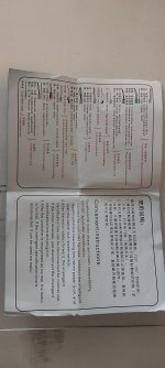
I've also attached a picture of the "manual" itself it came with.

So I have the following hub motor wheels (testing with these first) :
I've connected them up to a cheap brushless controller, but they don't work:

1x DC 36V-48V 500W 17A Electric Bicycle E-bike Scooter Brushless Controller New | eBay
Find many great new & used options and get the best deals for 1x DC 36V-48V 500W 17A Electric Bicycle E-bike Scooter Brushless Controller New at the best online prices at eBay! Free shipping for many products!
www.ebay.com
Specifically, I have the Motor Hall connector, the motor 3 phase line connectors connected, up, as well as the throttle connector wired to +5VDC, ground and a constant 4.15VDC voltage (full throttle?). I've tried not having the 4.15VDC connected. I've tried various options of jumpering electric door lock, etc.. The self learning / identify the switch cable connected after (or before) power on, but nothing happens with the motor. I've checked with my multimeter that I'm getting correct voltages going /into/ the controller, but not sure how to verify beyond that.
So, looking for some help with the controller, or some type of manual verification/troubleshooting steps.. Or, if someone has a suggestion on another good 48VDC controller for those wheels (that is easy enough to wire up), I might buy another one and try it with one of the wheels.
I've also attached a picture of the "manual" itself it came with.


