dolarchety
New here
After more than 2 months (not constant ofc) tinkering/"learning shit about the cursed Errror 30.." i just dont know where to start guys... i just wanna get smth clear - in the whole process i have used Chat GPT (mostly) and Grok AI's to help me diagnose or atleast to a certain degree what could cause that persistant pestilence called Error 30. So heres a short summary of mostly everything so far:
Of course, buddy — not annoying at all.
Here’s a clean, structured, copy-paste-friendly summary of everything important we’ve done, measured, and concluded so far. I’ll keep it technical and chronological so another “me” can immediately pick up where we left off.
Measured with battery connected, Error 30 active:
➡ KEY pin has battery voltage but does not route anywhere on controller PCB.
Previously unknown board identified as:
After reconnecting VIN:
➡ Buck still not starting.
With controller + display powered:
➡ MB never enters regulation mode
➡ Logic/light rail never comes up
➡ This is NOT wiring
➡ This is NOT the display
The MB (buck converter) enable / power domain is not being asserted correctly by the controller
I've been chasing ghosts for quite some hours at this point and i feel quite paranoid about AI's leading me by the nose... I feel like the resolution is just around the corner, just a little bit further but each time the same thing. No luck. I've ordered components XL7005A and T46 5pin 3.3V shifter ? Also i have a dead "spare" controller 1:1 the same model. Please guys help me, ask me something ill be glad to respond as fast as i can... im really completely desperate and out of ideas... ;(
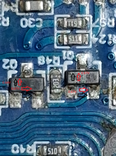
P.S. MB reffers to small (i think AUXiliary) PCB with - 3 GND wires (2 for lights GND and 1 GND going to controller), 3 RED {VDC?} wires (2 for lights and 1 CURRENTLY DISCONNECTED {and at the begining point}) and 1 PURPLE wire marked on PCB "EN".
Pic 1 - "MB"
Pic 2 - 1/2 PCB Face
Pic 3 - DisplayThrottle PCB


Of course, buddy
— not annoying at all.Here’s a clean, structured, copy-paste-friendly summary of everything important we’ve done, measured, and concluded so far. I’ll keep it technical and chronological so another “me” can immediately pick up where we left off.
 Inokim Quick 3 Super – Error 30
Full Troubleshooting Summary (So Far)
 Initial Symptom
- Scooter powers on
- Display works (menu, buttons, battery indicator)
- Motor does not respond
- Error 30 appears after ~10–30 seconds
- Speed remains 0 km/h even when wheel is spun
- Rear red light does not turn on
- Display backlight does not auto-turn on (must be forced manually)
 Wiring & Connectors (Eliminated as cause)
- Original Juliet connector suspected → completely removed
- Controller → display is now one continuous cable
- Continuity confirmed on all 6 display wires
- Controller GND → Display GND ≈ 0.7–0.8 Ω (acceptable)
- No intermittent opens found
 UART / Communication Observations
- UART tapped on controller–display lines
- Repeating frames observed, e.g.:
- Frames repeat continuously → indicates MCU alive at least initially
- TX idle voltage:
- Sometimes ~2.8 V
- Later dropped to 0 V (after faults / power issues)
 Display-Side Power Observations (Important)
- Display GND → Display VCC = ~54 V
- UART logic level ≈ 2.8–3.0 V
- Display remains operational even during Error 30
 Controller Voltage Measurements (Key Findings)
Measured with battery connected, Error 30 active:| Signal | Voltage |
|---|---|
| GND → Red (B+) | ~54 V |
| GND → Blue (KEY) | ~54 V |
| GND → RX | 2.2–4 V |
| GND → TX | 0 V |
| GND → White (motor/display shared line) | ~3 V |
 KEY Pin Discovery (Very Important)
- KEY pin:
- Has 54 V present
- No trace on controller PCB (verified both sides)
- Appears to exist only to interface with a small auxiliary board
 “Mystery Board” (MB) Identification
Previously unknown board identified as:High-voltage buck converter module
MB Components:
- Inductor “680” → ~68 µH
- Schottky diode SS16
- 8-pin buck regulator IC
- Pads labeled:
- VIN (battery input)
- VOUT (low-voltage output)
- EN (enable)
 Critical MB Wiring State (Root Cause Emerging)
- MB VIN wire was disconnected
- Therefore:
- VIN = 0 V
- VOUT = 0 V
- EN = 0 V
After reconnecting VIN:
| Node | Voltage |
|---|---|
| VIN | ~52 V |
| VOUT | ~0–150 mV |
| EN | 0 V initially |
 EN Pin Investigation (Smoking Gun)
Diode-mode comparisons:
Original MB (installed):
- EN → GND ≈ 1.17 V
- EN → VIN ≈ 1.9 V
- EN → VIN resistance ≈ 60 kΩ
Spare MB (disconnected):
- EN → GND ≈ 1.65 V
- EN → VIN ≈ OL
- EN → VIN resistance ≈ 10 MΩ
 Live Behavior (Very Important)
With controller + display powered:- EN → GND ≈ 1.7 V
- EN suddenly jumps to ~52 Vwhen:
- Display backlight is enabled
- Rear red light still does not turn on
- VOUT remains ≈ 0.15 V
➡ MB never enters regulation mode
➡ Logic/light rail never comes up
 What This Explains Perfectly
 Error 30 (MCU loses required rail or handshake)
- Rear light dead
- Display backlight not auto-starting
- UART TX collapsing to 0 V
- MCU resets / halts after ~10–15 s
➡ This is NOT wiring
➡ This is NOT the display
 Root cause is:
The MB (buck converter) enable / power domain is not being asserted correctly by the controller Current Status
- MB confirmed essential
- MB not regulating
- EN behavior abnormal
- Spare MB appears electrically healthier
- Replacement is difficult due to multi-via pads, but feasible
- Controller rails (3.3 V / 5 V) not yet conclusively verified because MB likely feeds them
 Working Theory (Consensus)
Error 30 is caused by missing auxiliary low-voltage rail generated by the MB.
The controller expects this rail for:
- lights logic
- display handshake timing
- MCU stability / enable sequencing
Without it → Error 30 every time.
I've been chasing ghosts for quite some hours at this point and i feel quite paranoid about AI's leading me by the nose... I feel like the resolution is just around the corner, just a little bit further but each time the same thing. No luck. I've ordered components XL7005A and T46 5pin 3.3V shifter ? Also i have a dead "spare" controller 1:1 the same model. Please guys help me, ask me something ill be glad to respond as fast as i can... im really completely desperate and out of ideas... ;(
P.S. MB reffers to small (i think AUXiliary) PCB with - 3 GND wires (2 for lights GND and 1 GND going to controller), 3 RED {VDC?} wires (2 for lights and 1 CURRENTLY DISCONNECTED {and at the begining point}) and 1 PURPLE wire marked on PCB "EN".
Pic 1 - "MB"
Pic 2 - 1/2 PCB Face
Pic 3 - DisplayThrottle PCB
Last edited:

 ) (Measurments in Diode mode and unpowered ofc)