jonescg
100 MW
Get your hands off it - I haven't opened it up yet for a good look. That can happen once I finish the bike.
However, looking through their patent documents, I discovered their stator has the most unique construction technique!
From the document:
The cooling loop is pretty space efficient too:

A very, cool, motor!
However, looking through their patent documents, I discovered their stator has the most unique construction technique!
From the document:
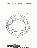
Boring Patent Lawyer said:The stators 100 will now be described in more detail. Each stator 100 is of the same generally flat, annular, shape. This is shown in FIG. 3, which shows a representative one of the stators 100. With continued reference to FIG. 3, a first surface of the stator 100 has many slots 110 formed therein that extend in radial directions across that surface, from the inner edge of the annular stator 100 to the outer edge. Each slot 110 includes a narrow mouth 112 at the surface of the stator 100 leading to a wider slot cavity 114. In cross-section, with the section being taken circumferentially, the slot cavity 114 is generally rectangular, but with radii at the corners. The slots 110 are angularly spaced from each other with constant angular pitch.
In this embodiment, each stator 100 is formed from a single long strip of electrical steel. This is not visible in the accompanying drawings. The strip has apertures punched in it all along one edge such that T-shaped projections remain between the apertures. The single strip is coated in an insulator and is then wound up into a roll to form the stator 100. The strip is wound up rather like a roll of adhesive tape. Once wound up, the apertures form the slots 110, with the T-shaped projections forming structure of the stator 100 in-between juxtaposed slots that define each mouth 112 and cavity 114. There are 54 slots in each stator 100.
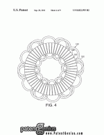
Each stator 100 carries windings of an electrical conductor thereon. FIG. 4 shows one representative stator 100 with a single winding 120. The winding 120 is made up of a cable of 16 parallel copper strands of approximately 0.5 mm in diameter. The winding 120 is arranged into many coils 122 that are accommodated in the slots 110 of the stator 100. Each coil 122 is placed in the slots such that one part of the coil 122 extends through one slot cavity 114 and another part of the coil extends through another slot cavity 114 spaced therefrom. Each coil 122 is formed from four turns of the cable in the two slots 110. In this embodiment, each coil 122 is accommodated in two slots 110 spaced apart from each other by four times the distance between juxtaposed slots 110. The winding 120 of FIG. 4 includes coils 122 that are wound in a clockwise direction with respect to the side of the stator 100 that includes the slots 110 and coils 122 wound in an anticlockwise (or "counter-clockwise")direction. There are twice as many clockwise coils 122 as anticlockwise coils 122. In winding the winding 120, coils 122 are wound sequentially in an angular progression around the stator 100. The winding of each anticlockwise coil 122 is followed bywinding two clockwise coils 122. One part of a first-wound one of the two clockwise coils 122 is accommodated in one of the slots 110 that accommodates part of the anticlockwise coil 122, and the other part of the first-wound one of the two clockwisecoils 122 is accommodated in another slot 110 spaced from the anticlockwise coil 122. The second-wound one of the two clockwise coils 122 overlaps the first-wound one, but is staggered therefrom by the distance between juxtaposed slots 110. The windingof the two clockwise coils 122 is followed by winding an anticlockwise coil 122 that shares a slot with the second-wound one of the two clockwise coils 122, but that otherwise does not overlap therewith. This winding pattern is repeated around thestator. There are six anticlockwise coils 122, and six pairs of overlapping, but staggered anticlockwise coils 122.
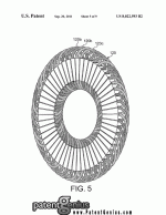
As can be seen in FIG. 5, there are three windings 120a, 120b, 120c in total. These are connected together to in a star arrangement to form a three-phase winding 125. Each winding 120 is angularly displaced from each other winding 120 by 120degrees. In alternative embodiments, a delta winding arrangement can be used.

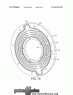
The cooling loop is pretty space efficient too:

A very, cool, motor!


