Is one pole BLDC without switching possible?

avada

1 mW
Joined
Sep 19, 2014
Messages
18
Hello!

This looks like the place to ask. I was wondering, if a DC motor could work this way, with only nort poles facing outward, and the south poles facing into the center. Which wouldn't need any sort of commutation/switching, I guess...

Something like this:
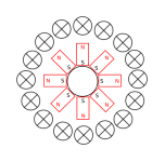
dc-motor.png

If something like this does work, then why aren't they used?
 
Hi.
No it wont work.
Srry.
 
Without a single switching mechanism to upset the rotor....it will simply sit at some point of attraction.
Simply energizing the coils will only move (or hold more tightly) at that point....you need some method to chase the magnets in a direction reliably if you want it to spin.


If it did work as drawn you would have a perpetual motion machine....
http://www.aerodesign.de/peter/2001/LRK350/LRK_in_action.gif
 
avada said:
Hello!

This looks like the place to ask. I was wondering, if a DC motor could work this way, with only nort poles facing outward, and the south poles facing into the center. Which wouldn't need any sort of commutation/switching, I guess...

Something like this:


If something like this does work, then why aren't they used?

Actually it will work until the wires get twisted. I think what you describe and attempt to diagram is called a homopolar motor. Like I said, without some type of brush or sliding electrical contact, the wires get twisted. Brushless configurations don't work because the return side of the coil cancels the first side and does not have a return path under opposite magnetic polarity.

I find homopolar dynamos (motors and generators) interesting. They have limited applications; more as generators than motors. There have been a few homopolar alternators and I believe some generators used in industry like refining Aluminum where something on the order of 30,000 Amperes are needed at 4 or 5 Volts. I had heard that the Navy was experimenting with them for shipboard catapults. Google homopolar motor and find some nifty little ones you can make out of a single cell battery and disc magnet.

https://www.google.com/search?q=homopolar+motor&client=firefox-a&hs=AS&rls=org.mozilla:en-US:eek:fficial&channel=sb&tbm=isch&imgil=_26Z_NoYC9W2XM%253A%253BYua0OwjczBYTFM%253Bhttps%25253A%25252F%25252Fwww.sparkfun.com%25252Fnews%25252F1332&source=iu&pf=m&fir=_26Z_NoYC9W2XM%253A%252CYua0OwjczBYTFM%252C_&usg=__N3R0GwnIb4HKgwiSvXjOfGw0bxk%3D&biw=1413&bih=675&ved=0CDoQyjc&ei=m8scVO6BMo6OyAT3l4GoBw#facrc=_&imgdii=_&imgrc=_26Z_NoYC9W2XM%253A%3BYua0OwjczBYTFM%3Bhttps%253A%252F%252Fdlnmh9ip6v2uc.cloudfront.net%252Fassets%252Fc%252F6%252F9%252F7%252Ff%252F52a919cc757b7fba068b4567.png%3Bhttps%253A%252F%252Fwww.sparkfun.com%252Fnews%252F1332%3B1000%3B750
 
Thud said:
Without a single switching mechanism to upset the rotor....it will simply sit at some point of attraction.
Simply energizing the coils will only move (or hold more tightly) at that point....you need some method to chase the magnets in a direction reliably if you want it to spin.


If it did work as drawn you would have a perpetual motion machine....
http://www.aerodesign.de/peter/2001/LRK350/LRK_in_action.gif
But it's not like that image. As I understand DC permanent magnet motors work because putting a conductor into a magnetic field and driving current through it exerts a force. Switching is needed because the poles alternate between N/S. As explained in this video for example: http://youtu.be/Y-v27GPK8M4?t=9m33s
 
major said:
Actually it will work until the wires get twisted. I think what you describe and attempt to diagram is called a homopolar motor. Like I said, without some type of brush or sliding electrical contact, the wires get twisted. Brushless configurations don't work because the return side of the coil cancels the first side and does not have a return path under opposite magnetic polarity.

I find homopolar dynamos (motors and generators) interesting. They have limited applications; more as generators than motors. There have been a few homopolar alternators and I believe some generators used in industry like refining Aluminum where something on the order of 30,000 Amperes are needed at 4 or 5 Volts. I had heard that the Navy was experimenting with them for shipboard catapults. Google homopolar motor and find some nifty little ones you can make out of a single cell battery and disc magnet.
Could you explain more this twisting part?

I'm not sure about it being the same as homopolar. What's shown described in wikipedia is a bit different: https://en.wikipedia.org/wiki/Homopolar_motor
Although on second look it maybe an analog to it. So I guess the problem is the same then: it's condemned into single turn only. Which I guess would need comparatively huge currents to provide useful torque in most applications

(There's also an unipolar motor which is not explained at all but is claimed to be synonymous with homopolar: https://en.wikipedia.org/wiki/Unipolar_motor )

Brushless configurations don't work because the return side of the coil cancels the first side and does not have a return path under opposite magnetic polarity.

This might make sense. But the return side should at least be weaker because it's farther away. (Unless you )
 
Thud said:
Without a single switching mechanism to upset the rotor....it will simply sit at some point of attraction.
Simply energizing the coils will only move (or hold more tightly) at that point....you need some method to chase the magnets in a direction reliably if you want it to spin.

I can't see how anything else could be expected to occur. Either this is an open-and-shut case, or the OP needs to provide much more detail on how he expects his idea to work!
 
avada said:
Could you explain more this twisting part?

Take your diagram:

file.php


I would interpret this to depict a radial flux motor with the axis of rotation at the center of the center blank circle. The lines of flux depart radially from the N poles of the magnets outward (radially) and pass thru the circles with X in them. Those circles with the X typically represent conductors (or wires) perpendicular to the page with current traveling down the conductor into the page. With the outward flux and downward current, a clockwise force is imparted on the 16 conductors. If they are allowed to rotate (make a motor), then the connecting wires delivering current to them get twisted. If you put a sliding contact on them, then you don't have a brushless device and the return current path will be of the incorrect polarity to sustain the force and motion. The solution is to put the power (current) source in the body or shaft of the motor (put a AA cell inside the center circle) and you end up with the cute little demo homopolar motors seen on the google page :)

https://www.google.com/search?q=homopolar+motor&client=firefox-a&hs=x3Q&rls=org.mozilla:en-US:eek:fficial&channel=sb&biw=1413&bih=675&tbm=isch&source=lnms&sa=X&ei=AsUdVN-VCdGHyATij4DIDg&ved=0CAcQ_AUoAg#facrc=_&imgdii=_&imgrc=_26Z_NoYC9W2XM%253A%3BYua0OwjczBYTFM%3Bhttps%253A%252F%252Fdlnmh9ip6v2uc.cloudfront.net%252Fassets%252Fc%252F6%252F9%252F7%252Ff%252F52a919cc757b7fba068b4567.png%3Bhttps%253A%252F%252Fwww.sparkfun.com%252Fnews%252F1332%3B1000%3B750
 
Punx0r said:
I can't see how anything else could be expected to occur. Either this is an open-and-shut case, or the OP needs to provide much more detail on how he expects his idea to work!

Isn't this essentially the same thing as he shows? It works. Kind of useless, but does work.

http://www.youtube.com/watch?v=EkU_JmtH3PU
 
major said:
I would interpret this to depict a radial flux motor with the axis of rotation at the center of the center blank circle. The lines of flux depart radially from the N poles of the magnets outward (radially) and pass thru the circles with X in them. Those circles with the X typically represent conductors (or wires) perpendicular to the page with current traveling down the conductor into the page. With the outward flux and downward current, a clockwise force is imparted on the 16 conductors. If they are allowed to rotate (make a motor), then the connecting wires delivering current to them get twisted. If you put a sliding contact on them, then you don't have a brushless device and the return current path will be of the incorrect polarity to sustain the force and motion. The solution is to put the power (current) source in the body or shaft or the motor (put a AA cell inside the center circle) and you end up with the cute little demo homopolar motors seen on the google page :)

I see. I intended the magnets be the rotor. It makes more sense. You just pass current through the stators. And you get force between the stator/rotor. Of course if I (newly) understand it correctly you cant jut put coils, unless you put the return path far away making the engine massively oversized (and wasting copper), or use parralel wires, which results in an obscenely large current in summary.

major said:
Punx0r said:
I can't see how anything else could be expected to occur. Either this is an open-and-shut case, or the OP needs to provide much more detail on how he expects his idea to work!

Isn't this essentially the same thing as he shows? It works. Kind of useless, but does work.

http://www.youtube.com/watch?v=EkU_JmtH3PU

Looks like it. Although it would be closer to what I imagined if they fixed the wire in position and allowed the magnets to spin.
Like this: https://youtu.be/iG0pzGcy4xU?t=1m20s

I think they imagined magnetic poles attracting each other which is not the working principle if I understand correctly, but the force created by the moving charge in a magnetic field.
 
major said:
Punx0r said:
I can't see how anything else could be expected to occur. Either this is an open-and-shut case, or the OP needs to provide much more detail on how he expects his idea to work!

Isn't this essentially the same thing as he shows? It works. Kind of useless, but does work.

http://www.youtube.com/watch?v=EkU_JmtH3PU

Hi Major,

Having just read your detailed description I now get how it's supposed to work :) I was looking at the picture and thinking the circle repented the faces of coils, rather than an end view.
 
If you had a different number of stator lobes it could work, but your power factor would be lower than alternating magnets because of the longer flux paths and lack of return path. If you removed the magnets and substituted steel, you would have a salient pole switched reluctance topology. It would naturally magnetize into pole pairs like a normal alternating magnet rotor.
 
johnrobholmes said:
If you had a different number of stator lobes it could work, but your power factor would be lower than alternating magnets because of the longer flux paths and lack of return path. If you removed the magnets and substituted steel, you would have a salient pole switched reluctance topology. It would naturally magnetize into pole pairs like a normal alternating magnet rotor.
How about something like a thoroidal motor. An appropriately magnetized rotor the stator would be helical a helical winding all around it. Then the return side for the coil wouldn't be a problem because there wouldn't be any.
 
Back
Top