Hello Endless-Sphere members,
this post is rather long. So you can skip the introduction if you want.
I've been working on my own frame for an electric bicycle for a while now. I already have some experience with electric vehicles. I built an ebike two years ago with 36V lead acid batteries that I put into the triangle of an old mountainbike. The bike was propelled with one of those chinese unite 1000W motors attached to the rack. The batteries couldn't even deliver close to the 30A that was needed for the 1000W. The motor performed very poorly the chain from the motor to the back wheel was loud because I had to use a very small sprocket on the motor to get a low gear ratio. I couldn't attach the motor properly, so it wiggled around. Same with the batteries. The breaks of the bike were ok. However they were of no avail since the tires were too thin and had bad traction. I crashed it into a car. I'm ok, the bike wasn't. When I look back, I am thankful for that. The bike was bullshit.
Next came a kart equipped with 80 lifepo4 Headway cells. 48V 50Ah. Controller was from Alltrax, 48V 400A set to 300A. Motor from a forklift. The driving time was sufficient for me, the kart was a pleasure to drive every time. I sold the kart last week though. The reason for this is that I don't have the possibility anymore to transport the kart somewhere I can drive.
Enough talk, you aren't reading this anyway.
______________________________________________________________
I have a new project!!! A new electric bicycle!
This time I'm doing it the right way. I want it to be robust, strong, offroad-capable, looking-nice-and-clean and reasonable fast. I'm talking something like 35mph without pedalling. I know there are some of you who have bikes going faster, but 35mph feels enough for me. The bike I crashed could reach this speed when I pedalled quickly and I felt like it was good enough. Nevertheless this bike will be way more powerful than my old one. Acceleration should be good.
Electric parts I'm going to be using:
So I'm going to use 32 of my Headway 38120 cells (3.2V 10Ah) for a configuration of 16s2p giving me roughly 51V at 20Ah. Why not higher voltage? I already have a 900W charger for 16s lifepo4. I'm probably going to build a homemade BMS. I've been interested in electronics since a few years. I will report later if this is working out.
Motor will definetly be Crystalyte HS3540. In combination with a 26" wheel I should reach 30-35 mph.
I already have a controller. One of Lyens modified Infineons with 12 IRFB 3077 MOSfets for low internal resistance. Max current is 45A as far as I remember. This gives me roughly 2250W of electric power.
First I bought a Downhill bike that will deliver robust parts like front fork, wheels, breaks, dampers...
Here it is:

Bike is from year 2006. It's got a Marzocchi 888 RC fork, FOX DHX 4.0 damper, 26" wheels that are 7cm wide. Breaks are 200mm front and rear. The breaking power of this bike is incredible even on bad surface. It seems to make a very good robust base for my built. The whole bike weighs 19kg.
Of course the frame is not suitable for an electric conversion. There no place to put a large battery. And as I said I want it to look nice and clean.
So, there is no way around it. I need to built a custom frame!
The frame will be three-dimensional instead of two-dimensional like a usual bicycle frame. This gives me plenty of room for batteries. I looked at a lot of different custom frames here on the forum. Much of my design is based on the builts members did.
This is what I've got so far:


No, I will not paint it coloured as these pictures show. Each colour stands for a specific tube dimension. More about that at the end of this post.
The way I started designing the frame was by going to the bike shop in my town. The frame of a downhill bike is definetly not suitable for riding long distances. The bike is designed to go downhill as it's name indicates. The bottom bracked is 45cm off the ground and the seat is set pretty low. On such a bike you usually pedal with your but off the seat, otherwise it's uncomfortable. Your legs will be much too short for it.
In the bike shop I took some full-suspension mountainbikes for a ride and looked for a frame that suits me well.
I found this bike:

A Trek Fuel EX 6 in size 19.5".
I took this picture directly from the side. Originally I thought I would copy the image into Google Sketchup to find out all important dimensions that affects the seating position. I was lucky I didn't have to do this. All dimensions were found on the internet on the webpage of Trekbikes.
http://www.trekbikes.com/de/de/bike.../mountain/singletrack_trail/fuel_ex/fuel_ex_6
I opened a new project on Google Sketchup and entered the important dimensions to give me a rough impression of how big my bike will be.

On the right you see the frame of the Trek Fuel with the datas I got from the internet.
On the left is my downhill bike in 1:1 size. I compared it with the frame of the Trek Fuel. For my custom frame I kept most of the dimensions of the Trek.The steering angle is set to 67°. I wonder if a lower angle would be better to give the bike more stability on high speeds.
The front fork of the DH bike is alot longer than the one on the Trek, so the steering tube is higher up.
I have widened the wheelbase to about 130cm. Thats 15cm longer than on the Trek.
As you see it is a tube-based frame. I saw others building frames out of sheet metal. There's too much welding involved that might result in deformed frames due to high temperatures. Besides I like the look of the tubes sticking out.
I'm going to use usual mild steel. It's available everywhere and costs like nothing. I am not a professional welder and I don't have good welding equipment. If the frame goes wrong I won't lost a fortune. I don't know where to get CrMo steel that is used mostly for bicycle frames. I assume it's also much more expensive than usual mild steel.
The material I would prefer after that is stainless steel. I heard it has better mechanic properties than mild steel when using for frames. Aluminium? I'm not sure if it's easy to weld. It's also more expensive.
So for a beginner, I think mild steel is perfect.
As I said I took lots of builts here on the forum as an example.
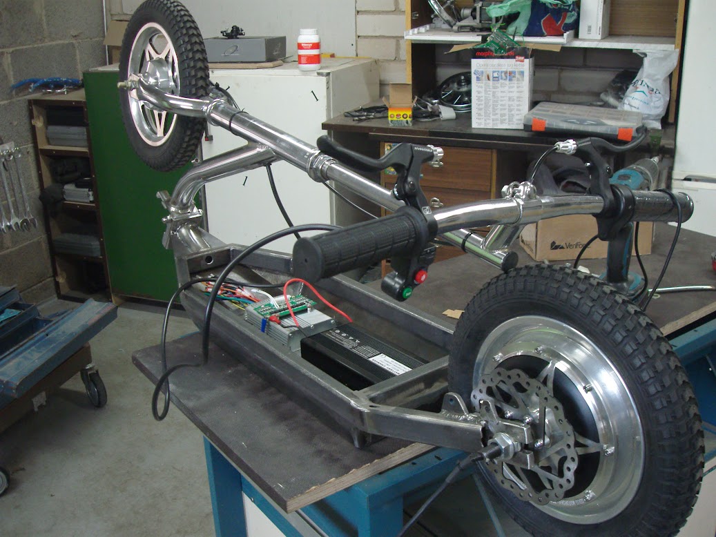
What inspired me most is this built here: http://endless-sphere.com/forums/viewtopic.php?f=6&t=29555
It looks great if not amazing and it is using steel pipes (although he used stainless steel). I didn't copy it exactly, but the rough look of it is the same.
My frame is more narrow. During pedalling I want my legs to move freely. The main frame right now is only 90mm wide. This way I had the problem placing all the 32 headways in there, so I chose widen the frame on the upper red tube to 110mm.

This is a pic from the bottom of the frame looking towards the rear wheel. You see the 90mm width of the frame gives enough clearance for the sprocket. In reality the clearance is even better, because I will move the sprocket more to the outside. I made sure the pedals never touch the frame.
The cover is shown in orange-reddish colour and is made up of Aluminium sheet AlMg3 with a thickness of 1mm.
A high resolution pic with the cover off:

Here you see that the upper red frame tubing is offset a bit.
The purple flat steel bars hold the battery tight. They are 3mm thick. The aluminium cover is attached to it by screws. You see the holes for it. With the cover on, I have 3mm space for balancing wires to go to the upper part of the frame where the BMS will sit.
A pic with one side cover off:

Without battery and elctronics

The other Aluminium covers will be screwed directly to the frame tubings. I have not drawn the holes for it, just imagine them.
I'm not sure if I will have the upper cover be made of Acrylic glass. It looks nice though.

If you take a look at the main frame I hope you notice that I kept the design simple. It should not be hard to fabricate it. I tried to make a lot of the tube connections two dimensional. What I mean by this is that you can work by printing out a 1:1 drawing of tubing connections and laying the tubings on to it. This way you can align the connecting tubings to make it pretty accurate. You also only need to mind one cutting angle.
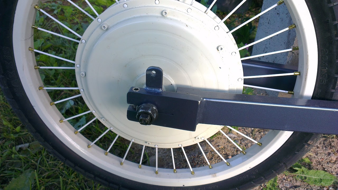
I have problems describing this. Look at this:
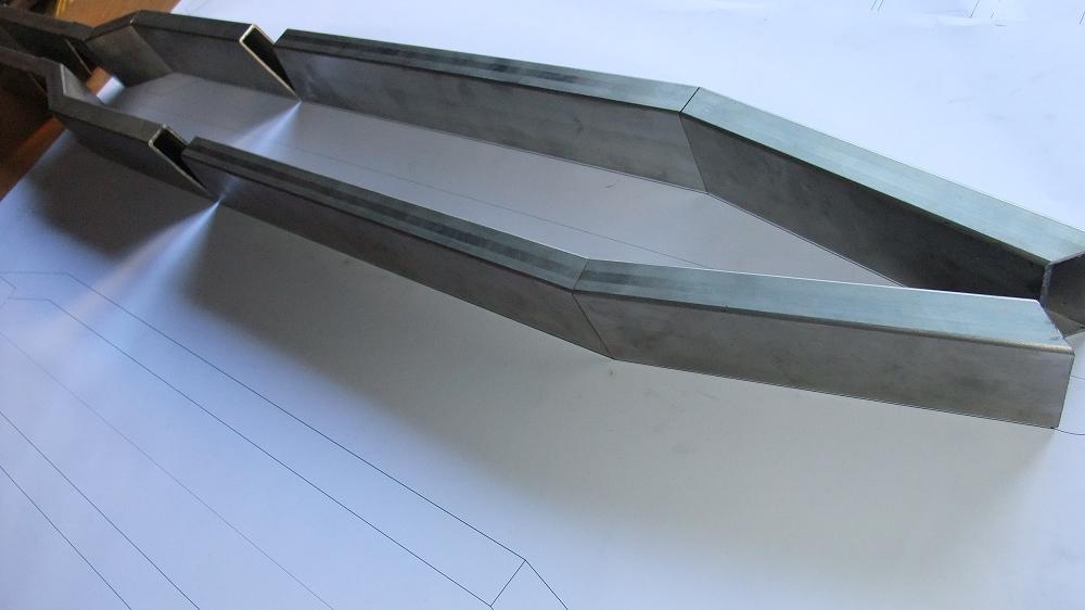
This pic is from the build that has inspired me most. He obviously did the same.
I know you can throw away a bike frame when the steering tube is attched in a wrong angle or to the side or some kind of it. To give some help, the upper red frame tubing is rectangular to the steering tube.
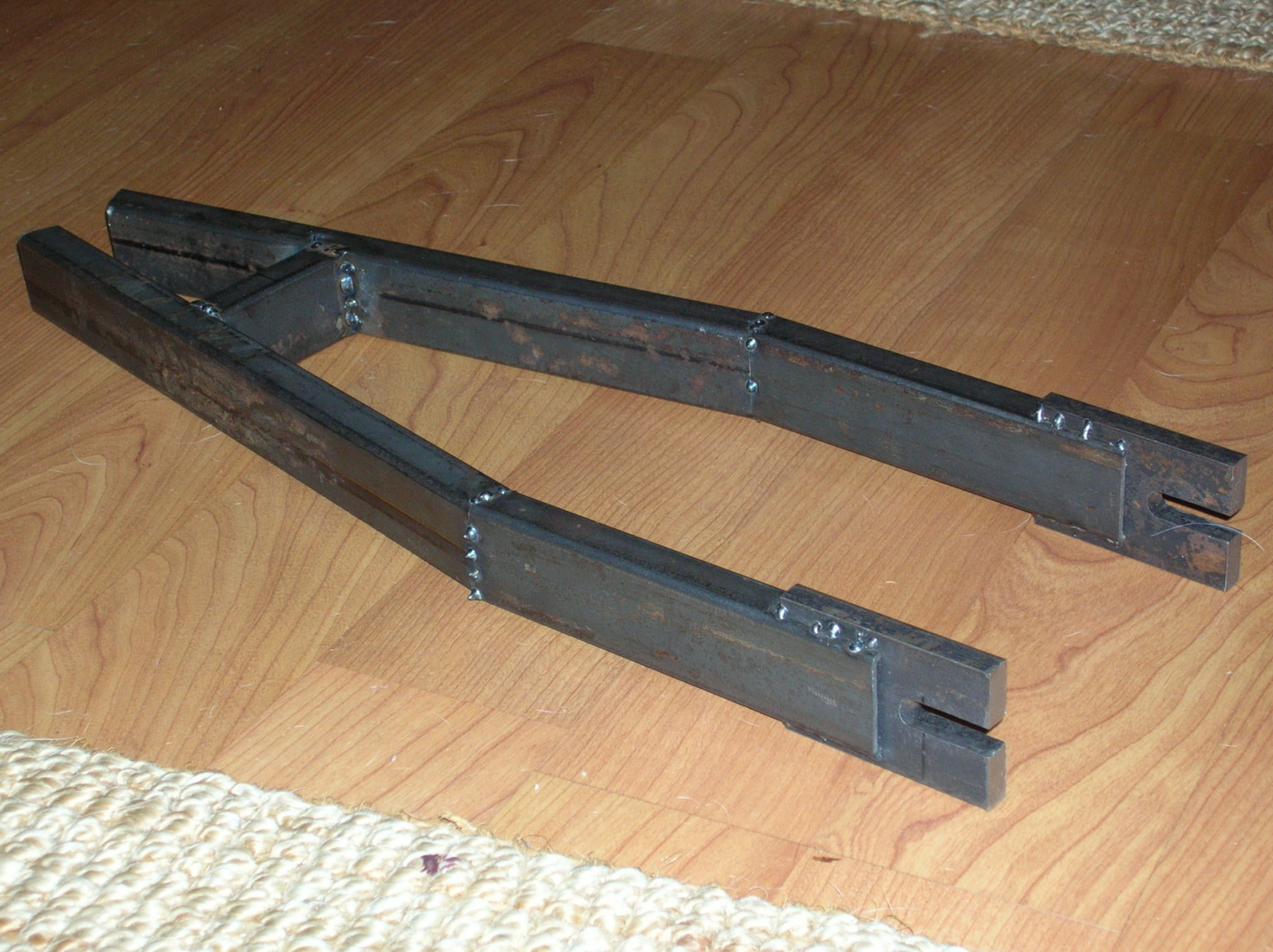
The swingarm:

The swingarm basically consists of two parts. The upper part is holding the damper.
I will change the two tubes connecting the two swingarms for a bend round tubing.
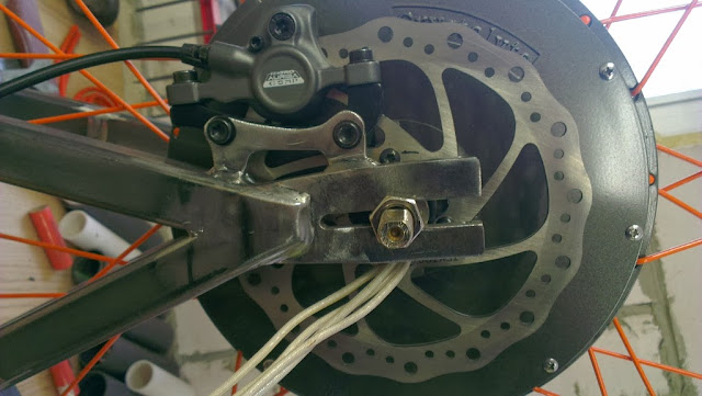
The swingarm also contains the bottom bracket which is 73mm wide in my case. I got the idea from Peter's thread recently:
http://endless-sphere.com/forums/viewtopic.php?f=6&t=50575
An amazing built by the way.
The brown tube in the middle is the bottom bracked. All brown parts are custom made parts that require a lathe. Maybe I will get a bottom bracket somewhere on the internet so I don't need to fabricate one.
The other brown tube is holding two bearings with an inner diameter of 10mm. I will put a bolt on there. Look at a picture of the main frame. You see the holes for this bolt.
This tube will be lathed in a way so that the bearings won't fall out.
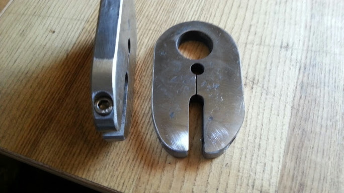
The dropouts are not completly finished as you see. The holding points for the brake callipers are missing for example.
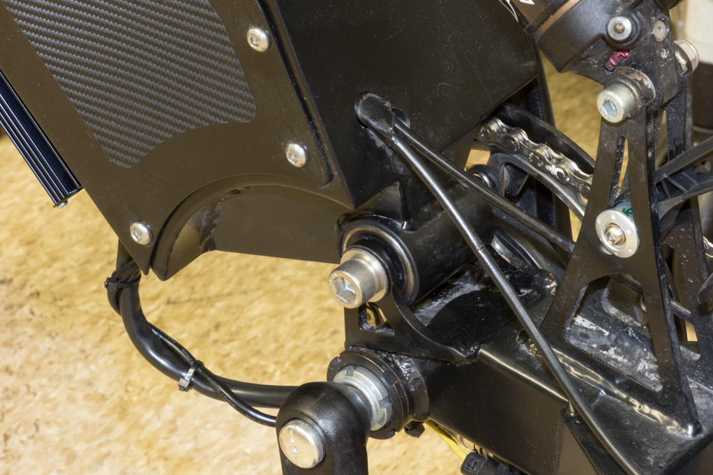
This pic gave me some inspiration:
It comes from the Thread "Evolution of Skill" and contains beautiful pictures taken during the process of welding etc...
http://endless-sphere.com/forums/viewtopic.php?f=6&t=23143
The colour code is as follows:
All dimensions in mm.
red : 30x15x2 used in the main frame
red-orange: 40x20x2 used in the swingarm
orange : 20x20x2 used in upper arm of swingarm
violet-pink: 15x15x1,5 used for holding the seat for example
purple: flat bar 20x3 used for holding the battery
yellow: flat bar 40x8 used for dropouts
orange-reddish: Alu sheet 1mm thick for the case
I made a list with the length of the tubings I need and calculated how heavy my frame will be.

On this list I included all tubings and the aluminium covers except for the brown custom parts. These custom parts and the damper ,small parts like the two bearings, screws, bolts etc. will lead to additional weight.
Right now my list says 10,24kg. The cost is about 25€ which is really low.
I wrote this article not only to thank the community for giving me the ideas and inspiration, I also would like someone of you to look over it and give me some feedback if I will encounter problems.
Questions I have:
1. I spend hours designing this frame. I paid attention all the time making sure the frame works out. However there could be possible mistakes. Does someone see something that might be a problem?
2. Second question goes to those who have experience with custom frames. How can I reduce weight? Which tubings can be smaller? By attaching the aluminium covers all around the frame I think this gives an enormous amount of stiffness to the frame, doesn't it? Can I for example replace all the red tubings (30x15x2) by a tubing like 30x15x1,5 or even lower? I don't want to go below thickness of 1,5mm though.
What about the 40x20x2 tube in the swingarm?
Or the dropouts. Right now they are made of 40x8 flat bar. They weigh a lot.
3. I want to use 1mm aluminium sheet for the covers. Is 1mm thick aluminium bending too much? I might need to get thicker material, what do you think?
4. As you see on the pictures, my damper now is attached differently. Does this design even work? Do you recommend a different swingarm design? Most mountainbikes have dampers going either into the frame or going down. None of them are going up. So I chose the first option.
5. My headways aren't yet attached properly to the frame. They're not moving side to side due to the purple steel bars, but they can move up and down the frame. Do you have a suggestion of how to get them tight?
6. Do you recommend a different steering angle? Mine is 67° right now.
this post is rather long. So you can skip the introduction if you want.
I've been working on my own frame for an electric bicycle for a while now. I already have some experience with electric vehicles. I built an ebike two years ago with 36V lead acid batteries that I put into the triangle of an old mountainbike. The bike was propelled with one of those chinese unite 1000W motors attached to the rack. The batteries couldn't even deliver close to the 30A that was needed for the 1000W. The motor performed very poorly the chain from the motor to the back wheel was loud because I had to use a very small sprocket on the motor to get a low gear ratio. I couldn't attach the motor properly, so it wiggled around. Same with the batteries. The breaks of the bike were ok. However they were of no avail since the tires were too thin and had bad traction. I crashed it into a car. I'm ok, the bike wasn't. When I look back, I am thankful for that. The bike was bullshit.
Next came a kart equipped with 80 lifepo4 Headway cells. 48V 50Ah. Controller was from Alltrax, 48V 400A set to 300A. Motor from a forklift. The driving time was sufficient for me, the kart was a pleasure to drive every time. I sold the kart last week though. The reason for this is that I don't have the possibility anymore to transport the kart somewhere I can drive.
Enough talk, you aren't reading this anyway.
______________________________________________________________
I have a new project!!! A new electric bicycle!
This time I'm doing it the right way. I want it to be robust, strong, offroad-capable, looking-nice-and-clean and reasonable fast. I'm talking something like 35mph without pedalling. I know there are some of you who have bikes going faster, but 35mph feels enough for me. The bike I crashed could reach this speed when I pedalled quickly and I felt like it was good enough. Nevertheless this bike will be way more powerful than my old one. Acceleration should be good.
Electric parts I'm going to be using:
So I'm going to use 32 of my Headway 38120 cells (3.2V 10Ah) for a configuration of 16s2p giving me roughly 51V at 20Ah. Why not higher voltage? I already have a 900W charger for 16s lifepo4. I'm probably going to build a homemade BMS. I've been interested in electronics since a few years. I will report later if this is working out.
Motor will definetly be Crystalyte HS3540. In combination with a 26" wheel I should reach 30-35 mph.
I already have a controller. One of Lyens modified Infineons with 12 IRFB 3077 MOSfets for low internal resistance. Max current is 45A as far as I remember. This gives me roughly 2250W of electric power.
First I bought a Downhill bike that will deliver robust parts like front fork, wheels, breaks, dampers...
Here it is:
Bike is from year 2006. It's got a Marzocchi 888 RC fork, FOX DHX 4.0 damper, 26" wheels that are 7cm wide. Breaks are 200mm front and rear. The breaking power of this bike is incredible even on bad surface. It seems to make a very good robust base for my built. The whole bike weighs 19kg.
Of course the frame is not suitable for an electric conversion. There no place to put a large battery. And as I said I want it to look nice and clean.
So, there is no way around it. I need to built a custom frame!
The frame will be three-dimensional instead of two-dimensional like a usual bicycle frame. This gives me plenty of room for batteries. I looked at a lot of different custom frames here on the forum. Much of my design is based on the builts members did.
This is what I've got so far:
No, I will not paint it coloured as these pictures show. Each colour stands for a specific tube dimension. More about that at the end of this post.
The way I started designing the frame was by going to the bike shop in my town. The frame of a downhill bike is definetly not suitable for riding long distances. The bike is designed to go downhill as it's name indicates. The bottom bracked is 45cm off the ground and the seat is set pretty low. On such a bike you usually pedal with your but off the seat, otherwise it's uncomfortable. Your legs will be much too short for it.
In the bike shop I took some full-suspension mountainbikes for a ride and looked for a frame that suits me well.
I found this bike:
A Trek Fuel EX 6 in size 19.5".
I took this picture directly from the side. Originally I thought I would copy the image into Google Sketchup to find out all important dimensions that affects the seating position. I was lucky I didn't have to do this. All dimensions were found on the internet on the webpage of Trekbikes.
http://www.trekbikes.com/de/de/bike.../mountain/singletrack_trail/fuel_ex/fuel_ex_6
I opened a new project on Google Sketchup and entered the important dimensions to give me a rough impression of how big my bike will be.
On the right you see the frame of the Trek Fuel with the datas I got from the internet.
On the left is my downhill bike in 1:1 size. I compared it with the frame of the Trek Fuel. For my custom frame I kept most of the dimensions of the Trek.The steering angle is set to 67°. I wonder if a lower angle would be better to give the bike more stability on high speeds.
The front fork of the DH bike is alot longer than the one on the Trek, so the steering tube is higher up.
I have widened the wheelbase to about 130cm. Thats 15cm longer than on the Trek.
As you see it is a tube-based frame. I saw others building frames out of sheet metal. There's too much welding involved that might result in deformed frames due to high temperatures. Besides I like the look of the tubes sticking out.
I'm going to use usual mild steel. It's available everywhere and costs like nothing. I am not a professional welder and I don't have good welding equipment. If the frame goes wrong I won't lost a fortune. I don't know where to get CrMo steel that is used mostly for bicycle frames. I assume it's also much more expensive than usual mild steel.
The material I would prefer after that is stainless steel. I heard it has better mechanic properties than mild steel when using for frames. Aluminium? I'm not sure if it's easy to weld. It's also more expensive.
So for a beginner, I think mild steel is perfect.
As I said I took lots of builts here on the forum as an example.
What inspired me most is this built here: http://endless-sphere.com/forums/viewtopic.php?f=6&t=29555
It looks great if not amazing and it is using steel pipes (although he used stainless steel). I didn't copy it exactly, but the rough look of it is the same.
My frame is more narrow. During pedalling I want my legs to move freely. The main frame right now is only 90mm wide. This way I had the problem placing all the 32 headways in there, so I chose widen the frame on the upper red tube to 110mm.
This is a pic from the bottom of the frame looking towards the rear wheel. You see the 90mm width of the frame gives enough clearance for the sprocket. In reality the clearance is even better, because I will move the sprocket more to the outside. I made sure the pedals never touch the frame.
The cover is shown in orange-reddish colour and is made up of Aluminium sheet AlMg3 with a thickness of 1mm.
A high resolution pic with the cover off:
Here you see that the upper red frame tubing is offset a bit.
The purple flat steel bars hold the battery tight. They are 3mm thick. The aluminium cover is attached to it by screws. You see the holes for it. With the cover on, I have 3mm space for balancing wires to go to the upper part of the frame where the BMS will sit.
A pic with one side cover off:
Without battery and elctronics
The other Aluminium covers will be screwed directly to the frame tubings. I have not drawn the holes for it, just imagine them.
I'm not sure if I will have the upper cover be made of Acrylic glass. It looks nice though.
If you take a look at the main frame I hope you notice that I kept the design simple. It should not be hard to fabricate it. I tried to make a lot of the tube connections two dimensional. What I mean by this is that you can work by printing out a 1:1 drawing of tubing connections and laying the tubings on to it. This way you can align the connecting tubings to make it pretty accurate. You also only need to mind one cutting angle.
I have problems describing this. Look at this:
This pic is from the build that has inspired me most. He obviously did the same.
I know you can throw away a bike frame when the steering tube is attched in a wrong angle or to the side or some kind of it. To give some help, the upper red frame tubing is rectangular to the steering tube.
The swingarm:
The swingarm basically consists of two parts. The upper part is holding the damper.
I will change the two tubes connecting the two swingarms for a bend round tubing.
The swingarm also contains the bottom bracket which is 73mm wide in my case. I got the idea from Peter's thread recently:
http://endless-sphere.com/forums/viewtopic.php?f=6&t=50575
An amazing built by the way.
The brown tube in the middle is the bottom bracked. All brown parts are custom made parts that require a lathe. Maybe I will get a bottom bracket somewhere on the internet so I don't need to fabricate one.
The other brown tube is holding two bearings with an inner diameter of 10mm. I will put a bolt on there. Look at a picture of the main frame. You see the holes for this bolt.
This tube will be lathed in a way so that the bearings won't fall out.
The dropouts are not completly finished as you see. The holding points for the brake callipers are missing for example.
This pic gave me some inspiration:
It comes from the Thread "Evolution of Skill" and contains beautiful pictures taken during the process of welding etc...
http://endless-sphere.com/forums/viewtopic.php?f=6&t=23143
The colour code is as follows:
All dimensions in mm.
red : 30x15x2 used in the main frame
red-orange: 40x20x2 used in the swingarm
orange : 20x20x2 used in upper arm of swingarm
violet-pink: 15x15x1,5 used for holding the seat for example
purple: flat bar 20x3 used for holding the battery
yellow: flat bar 40x8 used for dropouts
orange-reddish: Alu sheet 1mm thick for the case
I made a list with the length of the tubings I need and calculated how heavy my frame will be.
On this list I included all tubings and the aluminium covers except for the brown custom parts. These custom parts and the damper ,small parts like the two bearings, screws, bolts etc. will lead to additional weight.
Right now my list says 10,24kg. The cost is about 25€ which is really low.
I wrote this article not only to thank the community for giving me the ideas and inspiration, I also would like someone of you to look over it and give me some feedback if I will encounter problems.
Questions I have:
1. I spend hours designing this frame. I paid attention all the time making sure the frame works out. However there could be possible mistakes. Does someone see something that might be a problem?
2. Second question goes to those who have experience with custom frames. How can I reduce weight? Which tubings can be smaller? By attaching the aluminium covers all around the frame I think this gives an enormous amount of stiffness to the frame, doesn't it? Can I for example replace all the red tubings (30x15x2) by a tubing like 30x15x1,5 or even lower? I don't want to go below thickness of 1,5mm though.
What about the 40x20x2 tube in the swingarm?
Or the dropouts. Right now they are made of 40x8 flat bar. They weigh a lot.
3. I want to use 1mm aluminium sheet for the covers. Is 1mm thick aluminium bending too much? I might need to get thicker material, what do you think?
4. As you see on the pictures, my damper now is attached differently. Does this design even work? Do you recommend a different swingarm design? Most mountainbikes have dampers going either into the frame or going down. None of them are going up. So I chose the first option.
5. My headways aren't yet attached properly to the frame. They're not moving side to side due to the purple steel bars, but they can move up and down the frame. Do you have a suggestion of how to get them tight?
6. Do you recommend a different steering angle? Mine is 67° right now.