I've been pondering on how to get a reasonably high power low cost power supply/charger for my A123 pack for some time.
I have copies of an article from several years back on how to tear down and rewind a PC PSU for any arbitrary voltage. I modified a 360W one to produce 24V at 20A quite successfully, but it was a lot of work - it was also an older, simpler generation of PSU.
Current PSUs are smarter and probably more difficult to hack - but, here's an idea:
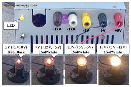
Take a high power standard PSU, chop all the wires off and apply a 5W load resistor on the 5V supply to ensure the PSU starts reliably. Now, identify the 'ends' of the 12V windings from the transformer (this is usually a single centre-tapped winding for both 5v and 12V - ie 12-5-0-5-12, there are then two centre-tapped pairs of Schottky rectifiers for the respective supplies) There is no separate adjustment for 12V, it is locked to the +5V rail.
So, we now have a 24V AC supply at a few tens of KHz.
We could:
1) Put a schottky bridge rectifier across the ends and get 28-30V DC after rectification and filtering (no current limit or control, but reasonably efficient) And on top of that, you can often get at least 50% change in voltage by tweaking the 5V adjust pot on the board, on old models anyway. So this simple approach might get you 45VDC or even more.
Warning, since the centre-tap of the winding is earthed, the output voltage is no longer referenced to earth, due to the bridge rec.
2) Put a Cockcroft-Walton voltage multiplier (chain of diodes and capacitors) to get any multiple of 24V that we want (not very efficient, but can generate quite a high voltage, perhaps if you have a 72V or higher but low capacity battery pack, still need some current control) By using two identical multiplier chains - one for each output winding of the transformer - and summing the outputs, better efficiency may be achieved and still retain a supply referenced to ground. Capacitors for this are a bit special and may not be cheap - unless scrapping old PSUs...
3) get a transformer core similar to the one in the PSU (by scrapping an old PSU) and rewind it - feed it 24V from the main winding and, say, dual centre-tapped 48-0-48V on the output side. Use a schottky split rectifier as in the original PSU - you now have 55-60VDC out, after rectification and filtering - depending on load. now use that raw DC to feed a constant current charger circuit.
A few guesstimated numbers: take a 500W PC PSU, 450W of that is probably available from the 5/12V windings. Lets assume 80% efficiency on our home-wound additional transformer. That gives well in excess of 300W for charging use, but it might get a bit warm in continuous operation, so derate a bit or add more airflow if that gets to be a problem.
While this has the disadvantage of having to rewind a transformer, at least you do not have to dig into the main PSU much at all and you can easily get any voltage you need.
There are so many models of PSU (and they change so rapidly) that trying to produce detailed methods for modifying a particular PSU are doomed to failure, hence my stab at a generic method. I don't know if the wire thickness changes between the 5V and 12V parts of the winding - it did not on the old one I rewound, if that has changed, output power would be limited somewhat.


