(Copied from my build thread, but relevant because it's motor guts):
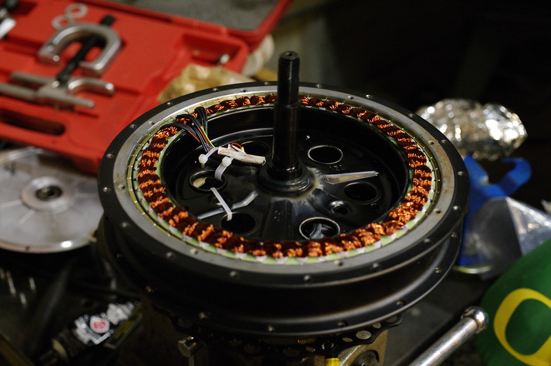
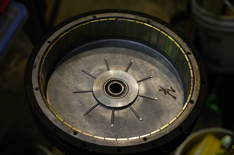
Update - 2015/09/15 - Popped the motor open today, looks very clean; in fact, maybe cleaner than Neptronix's motor.
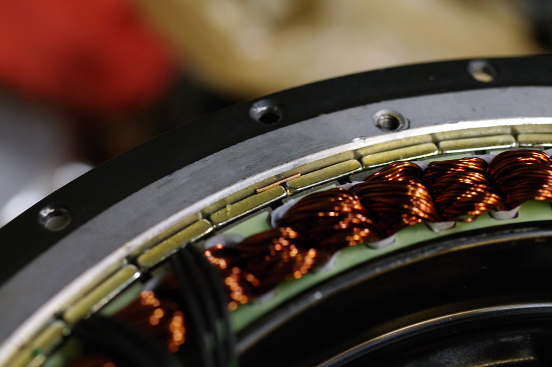
...Aside from this random piece of copper wire....

One of the halls doesn't look perfectly aligned...
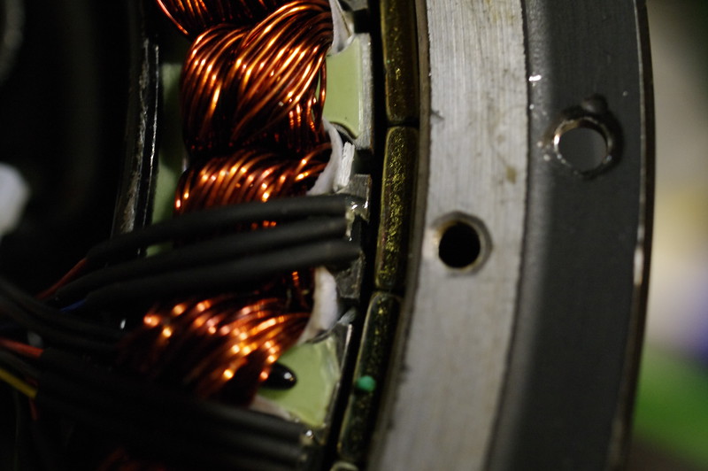
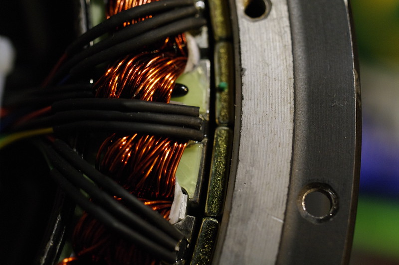
The rest are OK, though not as far out as they could be. There's slots for halls on the other side of the stator as well; I may order a few and swap out all of them with new ones aligned correctly; we shall see...
Also note the temp sensor poking out from under the windings... Hey there little guy!
Pulled the freewheel cover and magnets with this arrangement. Single-speed freewheel is a beast, I doubt it was damaged in the slightest from the (mis)treatment.
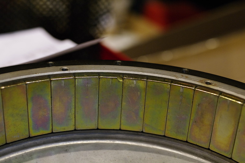
There was ZERO gap between any of my magnets, meaning they cut the right diameter for my motor; Neptronix's had had an issue where there was a gap, this just means that his can was fractionally larger in diameter than was optimal.
Only issue I see is one of my magnets is missing a tiny corner:
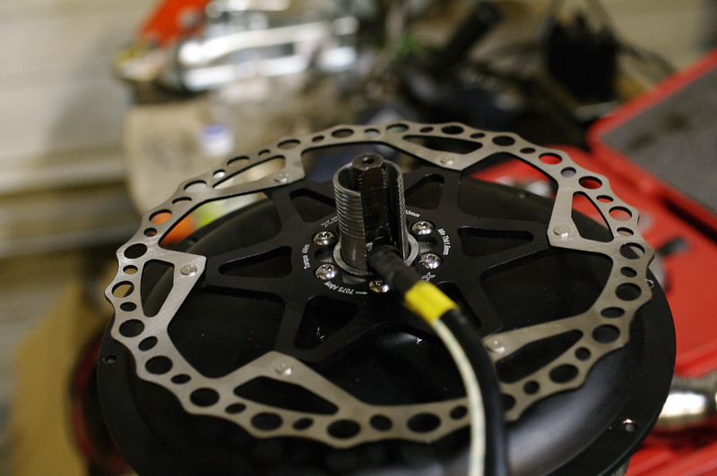
Oddly, the vanes were machined down on the ends on the freewheel cover. I have no idea why; I don't think there's anything even remotely near that they can hit...
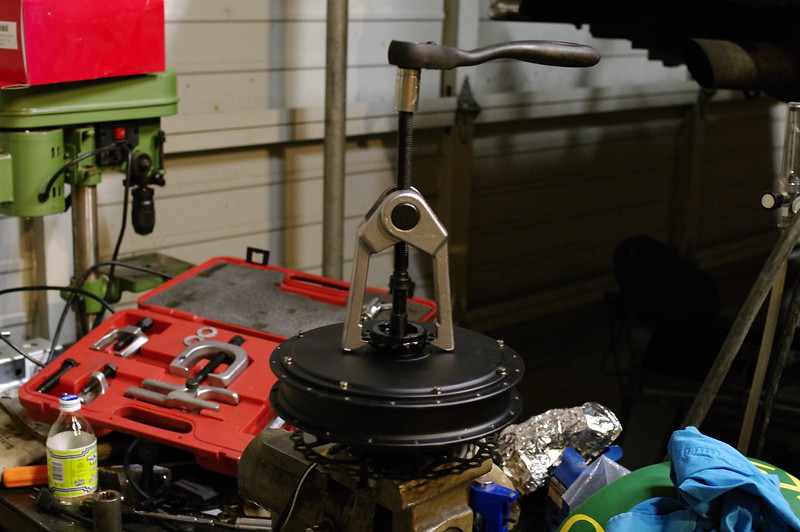
I turned down a water pipe coupler and cut a slot in it to avoid the cable bundle; should let me (eventually) press the bearing out of the brake-side cover without mangling the wire bundles.
Makes enough contact with the inner race of the bearing that it should allow me to slide-hammer or press it out; my next challenge is figuring out how to support the darn side cover with enough surface area that it A: doesn't distort, and B: pops the bearing. Seems like either they pressed in the bearings with a crap-ton of force, or they used some sort of glue or locktite.

")