LiFePO4 48v 15ah BMS issues

brainfarth

100 mW
Joined
Feb 16, 2013
Messages
45
Location
Oregon City, Oregon
I had my battery for about 2 months and then the first LED would stay on all the time. They sent me a new BMS, I installed it and after a few days, the pack was back to normal. But a week or two later, the first 2 lights would stay on. I'm talking to PING's customer service, trying to figure out what is going on. They asked me to measure the cells this time, and this is what I have come up with:
Voltage measurement after my ride to work:
03.18 06.45 09.73 13.01 16.29 19.56 22.90 26.20 29.40 32.80 36.00 39.30 42.60 45.90 49.20 52.50
6 hour charge and 30 minute wait until measurement:
03.28 06.60 10.32 13.86 17.40 21.00 24.50 28.10 31.70 35.30 38.90 42.50 46.10 49.60 53.20 56.80
50 hours since last charge and BMS unplugged the whole time:
02.77 05.77 08.91 11.98 15.06 18.12 21.30 24.40 27.60 30.70 33.90 37.00 40.20 43.40 46.60 49.70
Does this sound familiar to anyone?
 
how accomplished are you with the voltmeter?

do you have the regular BMS or the large high current version?

i fixed one by replacing the 5 pin comparator on the underside.

did you have the pack apart or accidentally short it out on the sense wires? or shorted to something on the pcb?
 
I'm fine with a volt meter. They instructed me to base my measurements off of the B- writtin on the board (not sure why). I don't know the version of the BMS. I don't think I shorted anything out since it wasn't plugged in at the time of the replacement board.
 
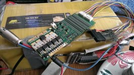
at the top of each row of shunt resistors you can see a three legged transistor. it is an SOT-23 package and it is a p channel mosfet that is turned on by the 5 pin SOIC underneath the board.

you can see the trace coming from the sense wire plug over the upper left leg. that is the source leg. the right leg is the gate leg and it is attached to the 5 pin comparator underneath by the trace going through the board underneath the gate leg. you should be able to see all this.

put the meter on 20V, put the red probe on the source leg, and put the black probe on the gate. measure the voltage. do that for every one of those transistor from channel #1 to #16. all the ones from 3 on up should read 0V but i wanna know what the voltage is on the gate of the first two.
 
Normally each string going to the BMS should read somewhere between 2.0v and 4.0v.
My guess is that if you measure 19v; you are measuring many string at once.
Third graph of this page could be helpful : http://scriptasylum.com/rc_speed/lipo.html

EDIT: If this is the only way you can measure; please do the math and post result of each string in the 2.0v-4.0v range (0.0v would be dead)
 
your #1 cell does not hold it's voltage for 50 hours.
this means there is a leak either internal to the cell or externally.
If its internal replace cell.
if it,s external removing the cell will stop the leak.
 
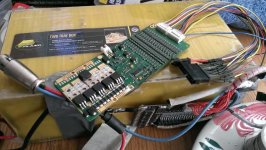
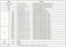
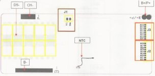
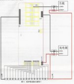
I am replacing the BMS that came with my LiFeP04 48v15ah Ping battery with a fancier model that has communications abilities. But I'm not sure about the mosfet's. Do I want to run solder across all of them like the way I have seen similar ones have been done?

IMAG0467 (Small).jpg
BMSpinout.jpg
BMSboard.jpg
BMSboardii.jpg
 
Back
Top