LTO battery question

Orphee

1 mW
Joined
Mar 26, 2008
Messages
12
Hi all

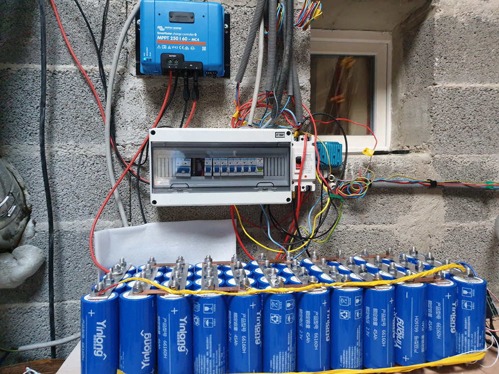
I build a "24V" LTO battery using 12X4 cells, 45Ah each)
I added a (bluetooth) BMS ( from https://fr.aliexpress.com/item/32997552090.html?spm=a2g0s.9042311.0.0.68b86c37BAbu8z )
Here a picture :
p8zx.jpg


I did this about two months ago. Here settings:

wgau.png


When I read cells values from phone application I see this

k6fq.png


Notice, most of time, there is a low power consumption, only 4G router and PTZ camera.

So I was wondering about values, is difference about cells normal ?

Thanks for you opinion
 
And the provider answered this:

"this problem is caused by poor battery cell voltage consistency .
you need to make a good cell voltage consistency .
take high voltage cell to discharge , take low voltage cell to charge "
 
Either the BMS isn't balancing your pack, or you're not giving it enough time to get the job done. If your pack is in a household solar system , it may not reach the maximum charging voltage often enough for the BMS's balancing circuit to work. It takes a long time to rectify imbalances in 180Ah worth of cells at a bleed rate of a few tens of mA.

Consider adding an active balancing circuit that works whenever an imbalance occurs, rather than only at the very top charging voltage.
https://www.ebay.com/itm/Li-ion-Lifepo4-LTO-Battery-Active-Equalizer-1-2A-Balance-2-17S-3S-4S-5S-7S-8S-US/383625412636
 
Every bms is different but doesnt balancing actually start at the last 0.20V, then when the bms does kick in, to balance its probably a very miniscule amount of current to charge and also a miniscule amount of current to discharge. I know with the lipo chargers it would take forever with a healthy pack to balance because the balance charge current was so low, then theres the discharge current which is also minimal. So depending on how out of balance it is, could take days or a week easy. I doubt any bms is better then a good lipo charger for balancing.

That is why icecube57 did a video on manually charging each cell for lipo.
https://www.youtube.com/channel/UCjqEv4Zd9h_4RGtD8golnQA/videos
The video I saw, might not be in the link but he would shove a pin into the cell thats low and charge it normally 1S. I cant remember if he shoved a pin in to a cell to discharge it.
 
Get a dedicated balancer, just use that BMS for its protective functions, and monitoring.

Hold your AC charger at a CV / Absorb stage around 2.6Vpc or thereabouts

ideally a current rate just a bit higher than the minimum to max out what the balancer can transfer from (higher) one cell-group to the (lower) ones.

long as it takes to get the cells within about 10-15 mV of each other.

____
Alternative, atomize the pack, put them all in one big parallel group, charge as above but at the 1S 2.6 voltage level

after that reached, let sit still connected, at least 24 hours, 48 better.

Then when you atomize, each cell sits isolated a couple hours

check voltages

if they've drifted apart much at all, you got likely poor quality cells, certainly not as well matched as they should be.

A set of well-matched brand new Grade-A cells fresh from the factory

in a low-C use case, avoiding the voltage "shoulders" top and bottom

should only need rebalancing every few months at most, could even go for years staying within 10-15 mV of each other.
 
The vendor is right. You must start with cells that are closer together in voltage than what you have now. Your example shows 2.63V to 2.381. As you've discovered, that's never going to work.

I hope this analogy translates OK, but think of the 12 cells as an hourglass timer. That's a piece of glass with a two storage chambers for sand and a funnel in the middle. Start with one chamber full of sand, turn it over and 3 minutes later (or whatever the timer was designed for), all the sand has fallen from the top chamber into the bottom one.

24138CCF-349C-42D4-A219-EECC39E8EEC6.jpeg

In your bank, you have 12 hourglasses, all must start with the same amount of sand in each chamber. So when discharging, they all run out of sand together, and when you charge, that sand is put back on the opposite side. At all times, the sand on either side should stay the same relative position across all 12 hourglasses. Otherwise, the BMS will stop all the hourglasses when any one of the 12 runs out, either charging, or discharging.

We call this cell balance. It's essential for all lithium banks. The sand is measured by the voltage. You should ideally have every cell read the exact same voltage, but that's near impossible. But if you see the middle cells at 2.2V, the rest should be say 2.18 to 2.22V. That's good enough. Expect more variation at high state and low state of charge.

Fixing your situation isn't easy. What Chalo suggested, a balancer, is one option. It will take some time, and is probably the easiest option. However, if you go this route, I suggest removing it (or turning it off) once balance is restored. Otherwise, you won't know if it's making a bad cell or cells. Once in balance, the bank should stay that way for some time, at least a month, normally at least 6 months with fresh cells. Or forever if the BMS built in balancer works well. If the bank won't stay in balance, more troubleshooting is required.

There are two other methods.

1) take the bank apart, wire all cells in parallel together making one really big 2.2V battery. Then charge to the manufacture's spec full charge voltage, somewhere around 2.6V per the BMS settings. Do the charge slowly, say 1-2A. Leave the cells connected after charging for 8-24 hours. Finally break it back apart and reassemble the 24V bank. This is normally done prior to installation to begin with. Sometimes in groups of cells, but following the exact same charging profile and wait times. This will require a lab type variable power supply, or a well regulated charger intended for this purpose for LTO cells. A lot of guys use chargers from the scale model remote controlled hobby industry.

2) For smaller imbalances, if you have lots of time...you can take 50ft of AWG 18 wire and short out the "high cells" one at a time to match your "lowest cell". Don't leave the wire coiled. This should be a safe rate, but make sure the wire doesn't overheat, warm is expected. More wire length lowers the heat if necessary. It will probably require a couple passes. You must physically monitor this exercise. The BMS won't protect the individual cell being discharged. However if the bank is basically working, this can be done in place, over time. Getting your 2.6V and 2.5V cell down will let the BMS get loads more charge into the bank. I would only suggest this if you have lots of patience. It's a cheap trick for fixing small imbalances, but yours is large. The only advantage is you don't have to break apart the bank or buy and trust a cheap balance board.

Good Luck!
 
Im using the same BMS on different setups, one on a 80Ah pack, and it works perfect without any extra balancing boards. You need to get the settings right, though. Can you post the rest of your settings? It looks it has shut down the balance circuit due to too much difference between cells. That is a programmable parameter. There is also a parameter where you choose at what voltage the balancer kicks in. Im using max cell voltage -0.2. So even if your cells are not perfect an drift a little at lower SOC, its still OK when they charge back up.

They are right that you should have started with a more even charge, but if you nail the settings and give it time I think it will work out.

And you should connect your temperature sensors.
 
What is the max balance current on that BMS?

Does it increase with a wider delta, slow down as they get closer?

What is the minimum "start balance" cell voltage?

And finally, what is the maximum "stop balance" delta mV?
 
john61ct said:
What is the max balance current on that BMS?
A: 10-200mA balance current

Does it increase with a wider delta, slow down as they get closer?
A: No, not that I am aware

What is the minimum "start balance" cell voltage?
A: There is defined a maximum of 4.6V, but no minimum voltage defined. "Cell diff value to start balancing" is also programmable from 0-4.6V. Not sure what is the actual lowest value before it ignores it. Im using 0.01 which works fine.

And finally, what is the maximum "stop balance" delta mV?
A: "Cell unit voltage Gap Protection" is programmable from 0-1V.

Answers above. I think the "Cell unit voltage Gap Protection" is the problem for OP. Im not 100% sure, but I think there is a message in green text in the status screen when the balance circuit is active, and the balance temperature should be higher if it is active. Then again, the discharge MOS is ON, so maybe I am wrong and the balance circuit is not in protection mode, IDK. Need to see the rest of the parameter settings.
 
When building your battery hook up big parallel groups and charge all these groups at same voltage before assembly and with all parallel groups the same voltage then take apart and reassemble into proper parallel and series groups then attach the BMS and fully charged. Next time.
What size are those cells where'd you get them how much ? Do you have a link ?
 
I'm sticking to post #7.

Balancing should only be done within a certain SoC% range,

Top (most common just because that is cheapest / easiest for vendors to implement)

or Bottom, often done manually

or Midpoint, usually how new Grade A cells are delivered, IMO best to just keep there if you are using purpose-built dedicated balancers

but the latter give you the choice of any voltage you like.

Balancing at more than one narrow voltage range is not only a pointless waste of time

but actually counter productive

as soon as you've bottom balanced

do it later at the top is just undoing your previous work.

Choose one point and stick to it.

So if a BMS does not even let you select the points at which you want it to start and stop balancing

it should not be allowed to do any balancing

if that function cannot be disabled, then it should be replaced.

200mA is way too low a balancing rate for cells that far out.

Get a balancer with at least an amp.

Or do it manually with an adjustable PSU in the 1S voltage range.


Chalo said:
Either the BMS isn't balancing your pack, or you're not giving it enough time to get the job done. If your pack is in a household solar system , it may not reach the maximum charging voltage often enough for the BMS's balancing circuit to work. It takes a long time to rectify imbalances in 180Ah worth of cells at a bleed rate of a few tens of mA.

Consider adding an active balancing circuit that works whenever an imbalance occurs, rather than only at the very top charging voltage.
https://www.ebay.com/itm/Li-ion-Lifepo4-LTO-Battery-Active-Equalizer-1-2A-Balance-2-17S-3S-4S-5S-7S-8S-US/383625412636


Thanks a lot for your idear, I will buy this. Update: I'm in France so I can't buy this item.
The pack is like a household solar system but ... I'm just using it 2 /15 days ! that's why it should be at maximum charge.
It's a very sunny place and, when I'm not here, only camera and 4G router are powered (some other thing are also solar powered but with independent solar system)
So I'm thinking there is two possibilities: some cells can't accept charge and limit it or BMS isn't precise.
 
HrKlev said:
Im using the same BMS on different setups, one on a 80Ah pack, and it works perfect without any extra balancing boards. You need to get the settings right, though. Can you post the rest of your settings? It looks it has shut down the balance circuit due to too much difference between cells. That is a programmable parameter. There is also a parameter where you choose at what voltage the balancer kicks in. Im using max cell voltage -0.2. So even if your cells are not perfect an drift a little at lower SOC, its still OK when they charge back up.

They are right that you should have started with a more even charge, but if you nail the settings and give it time I think it will work out.

And you should connect your temperature sensors.

Thanks all for your informations ! I was not expecting so much answers ! (sorry for my bad english, I'm french)
As I wrote , I'm just going to this "solar place" 2 days / 15 days.
The is NO classic classical voltage (220/110) , only solar power.
I will look at my phone next time to see other parameters (I took default LTO parameters and just change cells numbers and maximum power)
 
999zip999 said:
When building your battery hook up big parallel groups and charge all these groups at same voltage before assembly and with all parallel groups the same voltage then take apart and reassemble into proper parallel and series groups then attach the BMS and fully charged. Next time.
What size are those cells where'd you get them how much ? Do you have a link ?

Here is the link (45Ah cells)
https://www.alibaba.com/product-detail/LTO-Battery-for-30ah-35ah-40ah_1600082474647.html?spm=a2700.shop_pl.41413.23.214d3ff1PNrrgQ

Before connecting them I have verified voltages (to avoid too different levels when I connected them in parallel) and didn't find problem but probably I was not looking for small differences, expecting BMS will do the job.
 
Orphee said:
Chalo said:
https://www.ebay.com/itm/Li-ion-Lifepo4-LTO-Battery-Active-Equalizer-1-2A-Balance-2-17S-3S-4S-5S-7S-8S-US/383625412636

Thanks a lot for your idear, I will buy this. Update: I'm in France so I can't buy this item.

https://www.ebay.fr/itm/Active-Balancer-Module-Board-Li-Ion-LiFePO4-NMC-LFP-3-6V-3-7V-12V-24V-48V/254796509224
 
And BTW nothing to do with your balancing issue

But 12S for LTO is nominal 27.6V

charging at 31-32V would be good for longevity.


10 or 11S would get you closer to nominal 24V

Just out of curiosity, what is the CV / Absorb setpoint of the Victron SC ?

Is the AHT value left at the default setting?

Once you have corrected the current extreme delta problem, get them all within 10-15mV

which I doubt your current BMS can do

Then assuming the cells are OK, it is possible that BMS could do the maintenance job

if you can set it to start at a lower voltage, earlier in the charge cycle

and keep the Absorb stage holding longer at the CV setpoint before stop-charging, i.e. dropping to Float
 
Chalo, those super cheap balancers look too weak to me

> When the battery error voltage is above 0.1V, the balance work is started until the error is stopped at 30mv.

Must mean balance process starts only when the delta is 0.1V

that is starting way late IMO and stopping way too soon, should be more like 0.030 and 0.015 IMO

> the balance current is 0-1.2A, and the battery voltage difference is smaller. The smaller the current, the static power consumption does not exceed 20uA!


I bet that means over 1A only when the delta is huge, like a half volt, which should never happen.

When the delta get small, so does the current rate, maybe no faster than the OP's current BMS.

The term "active" balancer gets abused by the marketeers, but basically you should look for verbiage like "equalizing current does not vary with the voltage difference of the series-connected cells in the pack"

Several labeled "2S-24S" seem to qualify

https://www.amazon.com/Equalizer-Battery-Balancer-Capacitors-Continuous/dp/B07SFCY36G

"balance current is set independently in the range of 0.1~2A, independent of the cell voltage difference"

Otherwise correcting that much imbalance can literally take many many days

holding the input current in the range where it is active

without overcharging

can be a bit tricky.

Personally I'd first get to mains power with the pack, and use one of the alternatives I outlined in my first post.
 
Chargery has a great rep for long-term reliability

https://www.chargery.com/BMS16Pro.asp
 
https://www.ebay.com/itm/2A-Balancer-Li-ion-Lipo-Lifepo4-LTO-Battery-Active-Equalizer-2S-24S-BMS-APP-US-/184036148943
 
john61ct said:
And BTW nothing to do with your balancing issue

But 12S for LTO is nominal 27.6V

charging at 31-32V would be good for longevity.


10 or 11S would get you closer to nominal 24V

Just out of curiosity, what is the CV / Absorb setpoint of the Victron SC ?

Is the AHT value left at the default setting?

Once you have corrected the current extreme delta problem, get them all within 10-15mV

which I doubt your current BMS can do

Then assuming the cells are OK, it is possible that BMS could do the maintenance job

if you can set it to start at a lower voltage, earlier in the charge cycle

and keep the Absorb stage holding longer at the CV setpoint before stop-charging, i.e. dropping to Float


I'm at work and far from my tiny solar "house".
I remenber I decided to to set Victron at max LTO value + a little, perhaps one or two volts more, this because I saw I was not at maximum value. Because the BMS should stop the charge too...
The small converter accept maximum (theorical) value.
Why I choose 12 cells ? because low voltage would be probably too low ... not sure.
I also bought a 24V 220V 3000W Epever pure sinus converter but I didn't connect it until now.
 
Honestly, unless some of the cells have huge self discharge I dont see why this would not work with the current BMS (but better settings). Bleed off group 1, 5 and 11 and set it to balance above say 2.5V, then let it sit above that voltage and do its work. As long as it stays in that voltage range it should be in balance next time you arrive. I dont know the cells, but if they are not really good matched they will go out of balance when close to empty. Then unless they are self discharging, they will be back in balance when you charge the pack up again. If the BMS has been balancing all over the voltage range, it will be a mess. If the pack needs huge current to keep the balance you have a bigger problem, IMO.

Btw, it is not charging because cell 1 has reached "cellhighprotect" of 2.7V, and the "cellhighrecover" is set to 2.4V, which is unescessary low.
 
I bought an active BMS, this one, and will receive it in a few days (I will probably be back to my solar house in two weeks) so I will do some tests.

https://www.ebay.fr/itm/Active-Balancer-Module-Board-Li-Ion-LiFePO4-NMC-LFP-3-6V-3-7V-12V-24V-48V/254796509224?ssPageName=STRK%3AMEBIDX%3AIT&var=554613920639&_trksid=p2060353.m2749.l2649
 
Back
Top