madact's e-velomobile

madact

100 W
Joined
Jun 20, 2010
Messages
131
Location
Adelaide, South Australia
After a bit of uncertainty, I've decided to stick the build log here, as it's more about discussion than pictures...

Not very far along yet - I have a side-elevation blueprint, a bunch of steel tubing, a box o' shiny new bike parts and a half-built workbench (to be completed this week)

As the saying goes - watch this space :D
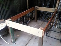
photo 2.JPG

The basic layout will be two steered wheels front, one driven wheel rear. 700C wheels all round, and all wheels will lean (the bike won't, though). It may not end up being quite this close to the ground in e-bike mode, but the race courses here are much like the criterium courses for regular cyclists, so it will be jacked down for racing - I'm going with 'forks' that simply bolt on at three joints (two about 40cm apart for the rotation axis, one for the steering pushrod), rather than a more traditional 'headstem' arrangement - swapping between sets of forks for different purposes should take all of 15 minutes.

The side view (and cutting list):
View attachment photo 1.JPG

Because this is being built as a velo from the ground up, and to comply with local competition rules which require rollbars and all sorts of anti-intrusion protection, it will have a fairly substantial framework which would cause drag on an unfaired vehicle - the body shell design is TBD, as I haven't got a good 3D CFD setup running yet (hoping to use OpenFOAM, but it's not exactly user-friendly)...

The motor to go with it will also be a custom build - ironless axial-flux, mounted to the disc-brake carrier on the rear wheel. This configuration is ideal for a velo on the flat going long-distance, as the efficiency is staggeringly high in the 60-110kph speed range when operating in the (locally legal) 200W range. Will post a design/build log for that separately - started one on motoredbikes, but it has mostly consisted of explaining things to safe :? figured I might get some more actual input here.
 
It sounds really cool! I can't wait to see you begin!
otherDoc
 
Am I the only one who can't see the pictures?
Looking forward to the build & more progress on the motor design.
 
Thud said:
Am I the only one who can't see the pictures?
"The selected attachment does not exist anymore." :(

Watch this space indeed...
 
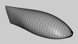
Well, now that the images are more-or-less under control, here are a couple of screen-shots of the concept body design I knocked up in a demo version of Rhino (1 session, 1 save :D) from some low-drag airfoil profiles I tuned for slightly larger T/C ratio, applied a cube-on-square transform to and lofted...

body 1.png

body 2.png

body 3.png

It probably wouldn't go too badly if I just built it as pictured, but I really want to do some simulation on it before building it (anyone know how to drive OpenFOAM?). Also, the model pictured has some nastiness going on in the nose region and the top 'edge' of the tail, on account of the splines being used - better parametrization of the shape would be good (I might subvert the XFLR5 body-generation code for it...); what I'd really like to do is run a genetic algorithm using custom parametrization feeding into XFLR then OpenFOAM, but I haven't gotten past meshing the simulation scenario so far :roll:

The laminar flow profile should be evident in the top elevation - I wanted to achieve laminar flow over a good proportion of the body, but I don't see a foil section attempting 80% laminar flow (like the current crop of speed record bikes) as being practical in real-world conditions, hence the less pronounced wedge (which seems more tolerant of surface imperfections when simulated in 2D using JavaFoil) and gentler angle after the transition point (at about 60%), where I'm thinking vortex generators might be a good idea. All speculation until I have 3D CFD to check it with, of course :x
 
How will you be getting the design from the pc to reality, all well and good a nice 3d drawing etc but if you can't replicate it exactly its , well...all pretty pointless how well it works/looks on the pc screen isn't it? You would need a large table cnc machine to mill it from foam i know that LoL... Sorry i'm not up with all the fancy gadgets your "edubicated" ones use, if it was me i would be calving a half out of a lump of foam then using this as a plug to make a mould, would all be freehand with bock and sandpaper/rasp and maybe rule for the occasional measurement..

Shall be Following with interest to see how this is all accomplishd the "scientific" way... best of luck...

KiM.
 
AussieJester said:
How will you be getting the design from the pc to reality, all well and good a nice 3d drawing etc but if you can't replicate it exactly its , well...all pretty pointless how well it works/looks on the pc screen isn't it? You would need a large table cnc machine to mill it from foam i know that LoL...

Following with interest mate best of luck...
KiM.

There are... older methods... but yes, that is the most realistic (and far less time-consuming than old-fashioned boat-fabrication methods). I have the most of the bits for a modestly sized 3-axis machine (80cm x 50cm x 20cm working area), not massively high res (0.1mm should be more than enough for the stuff I want to do with it). Saving on linear bearings and ballscrews by using stuff cheaply available from the local HW store (it's not like I'll be doing circuit boards on it, they have a machine at work for that :wink: ). The idea is to CNC the foam in slices, with alignment slots, stick it together, and hand-finish the mold. May have to do it in a few sections, of course - left and right sections at the front end, top and bottom at the rear - to get it onto the CNC table.

Of course, the windscreen bubble will be less controllable - the worst worry is uneven heating resulting in ripples or bulges, but even with that all sorted out, there's a real limit on how much you can control polycarbonate blowing (not to mention that I haven't done blow forming on anything like this scale before, and not since high school)... one of the other reasons I'd like the genetic algorithms running is so I can take the the bubble in to work and get it laser scanned, then tweak the body shape to get the most of how the bubble came out.

Luckily, body fabrication is likely to start around December at the earliest, so have plenty of time to work out the details.

And yeah, goodness knows how all the theory will translate into reality - as a tradie friend of mine points out, engineers have a tendency to miss the practicalities (not having unlimited cash being the one I tend to run into most often). We'll see, I guess...
 
Excellent so we will also see a cnc machine as part of the build process :) I am half way through making my own mill, put it on hold to make last bike LoL..


May father made motorcycle fairings for a stretch there in the mid 70s and built a contraption to blow the plexi to make the screens, was quite clever for the day i thought.

I have some good Australian links for stepper motors/electronics etc for the cnc if needed?

BEst of luck

KiM
 
Better steppers is always good... I have a small collection of salvaged computer bits, but bigger units with more appropriate gearing would make the whole thing simpler. Doing the skate-bearings-on-angle-iron trick for linear bearings, and simple threaded rod with spring-tensioned nuts for anti-backlash; it ain't a production machine, after all, and if it does wear out, the replacement cost is less than prohibitive.
 
Any reason not to just draw it out full size, make some templates and start shaping foam?

CNC is awesome, and very fast. For one-offs though, it's hard to justify the lag time to actually build one.

I would guess that you will have approximately 15 hrs of work to rough out the foam by hand (including making templates)

I would guess that building a CNC would be at least double that, and that's before you can start ANY work on the foam. And once you start, no matter what, you'll want to finish the CNC so debugging is part of that too.

Perhaps you want CNC and as a secondary thing, a shell. If so, go at it. If the shell is the primary thing, and the CNC is secondary, then perhaps manual is the way to get it done. I know that I am famous (at least in my own mind) for starting grand plans rather than just GET IT DONE the fastest way possible. As a result, many of my plans have come to naught.

Speaking of which, I should be out in the shop right now.

Katou
 
As far as equipment goes I'm building myself a decent sized workbench (2.4m x 1.2m - should be done this week), a small vacuum forming table (1.2m x 0.9m - ETA <2 months), and a CNC router (working area ~0.8mx0.5m - ETA <5 months). I have a number of uses planned for all of these (velomobile is just the first), and I'm sure I'll think of other things to do with them, too :mrgreen:. I already have a decent welder, angle grinder, drill press, inexpensive tube bender and a full set of hand tools, and have access to a PCB router / milling machine, so I'm well on the way to being set up for most any project I want to tackle. Building a decent CNC table is a project in itself, too :wink:
 
madact said:
Doing the skate-bearings-on-angle-iron trick for linear bearings, and simple threaded rod with spring-

This is how i originally planned to do it but then opted for a method i came up with using smaller bearings and polyethylene. Bearings were a far bit cheaper than the skate bearings.

The two links to Australian suppliers, i am blowed if i can find them, i just went through my CNC mill worklog and they aren't there i swear i listed then...if i come across them i shall post them for you matey...Making me want to resume work on mine now, i have made some room to fit the mill in the garage now too...hrmz...maybe finish that rather than start the next carbon fiber framed cruiser?

KiM

p.s I also wanted to use threaded rod from hardware, and bought it too, then saw mills using it, they are sloooooow might want consider a belt setup?
 
That table is some cool engineering AJ! Is that the slippery plastic stuff or did you cut up some plastic chopping poly boards. That would be a bit more cost effective, I think, than PTFE stuff. Great work as usual!
otherDoc
 
docnjoj said:
Is that the slippery plastic stuff or did you cut up some plastic chopping poly boards.

HAHA no mate, i bought a couple of meter square sheets of polyethylene to make the slides and part of the table from.

Unfotunately the trained bevers are still doing the cutting as i haven t finished the cnc machine yet... :: sigh ::

KiM
 
AussieJester said:
madact said:
Doing the skate-bearings-on-angle-iron trick for linear bearings, and simple threaded rod with spring-

This is how i originally planned to do it but then opted for a method i came up with using smaller bearings and polyethylene. Bearings were a far bit cheaper than the skate bearings.

You have got to be kidding me - skate bearings (bog standard 608) are like a dollar to a dollar fifty (USD, but who's counting) each, delivered
http://cgi.ebay.com/Racing-Skateboard-ABEC-7-Roller-Bearings-Sealed-Bearing-/7162655095?cmd=ViewItem&pt=LH_DefaultDomain_0&hash=item1aaed7177

That works out to under 50 bucks (AUD) of bearings if you want to put bearings all over the thing - strictly speaking, should only need about 30 tops... whatever shall I do with all the money you've saved me :wink:? Still, any saving is a good saving, so fire away...
 
madact said:
You have got to be kidding me - skate bearings (bog standard 608) are like a dollar to a dollar fifty (USD, but who's counting) each, delivered
http://cgi.ebay.com/Racing-Skateboard-ABEC-7-Roller-Bearings-Sealed-Bearing-/7162655095?cmd=ViewItem&pt=LH_DefaultDomain_0&hash=item1aaed7177

And i paid a tad more for 3 times as many bearings, guess you didn't notice i use 16 bearings per linear carriage thats 32 just for the table before we get to the rest of the cariages.

madact said:
whatever shall I do with all the money you've saved me :wink:? Still, any saving is a good saving, so fire away...

I prolly put it towards food, if you ever have to get by on a disability pension perhaps you will understand why I try to save money when i can.

Shall sit quietly and watch you obviously have it worked out, best of luck :wink:

KiM
 
AussieJester said:
And i paid a tad more for 3 times as many bearings, guess you didn't notice i use 16 bearings per linear carriage thats 32 just for the table before we get to the rest of the cariages.

I did, actually - myself, the table will be made from some hunks of 2-inch-think water-resistant chipboard of which I happen to have a whole bunch lying around, so I can get away with just a few - no rigidity problems, so I don't have to support it evenly. I happened to get lucky at uni, I was visiting a friend in on-campus housing when they upgraded the kitchen benches for a whole row of apartments - they were chucking out all the bits they cut out when they put the sinks in :mrgreen: so I have about a dozen pieces the size of a good Aussie double sink with drainers ear side...

So you're saying about 50c per bearing then? What size, might I ask? (A standard part number will do, I can look up the dimensions). I am interested, just slightly incredulous of the pricing...

AussieJester said:
I prolly put it towards food, if you ever have to get by on a disability pension perhaps you will understand why I try to save money when i can.

No, for sure, I do understand - my part time job at uni was the first actual income in the family for about a decade, mum's on a pension and in a housing trust home, I'm renting, trying to pursue projects and getting paid monthly. Every little bit does help. But if you look at what the average CNC router "home-builder" is doing around the 'nets, most are like "now on todays video log we take the samayabuchithatsexpensive anti-backlash ballscrew assembly and attach the mounting plate for the omigidianthowmuchwasthat stepper motor and connect it to the hakanayapayforitanyway stepper controller using this special anti-backlash wiring I picked up for only $200..."

OTOH, when one is working, some things are worth the time/cost tradeoff. And others aren't. It's always tricky.
 
Madact,
For sure there are a lot of guys trying to make a few $ selling their cnc ideas out there.... I did a sk8 beearing guide for a moving gantry cnc (now scraped for lack of rigidity)
P3200005.jpg

P3220012.jpg

P3220009.jpg

I have been building or rebuilding a home cnc for ever it seems...the ony one that hasn't changed is the cnc hot wire cutter, I have the mini super rigid rig waiting for a spindle.....But entertain the idea of a large unit suitable for making size of contures you are descibing. I have need for a larger unit already to make custom carbon fiber wheel patterns.....allways another project in mind.

Don'tsendbubbamail & a couple others are also a home cnc machinists here. I can only assume AJ will quit posing soon & get back to work!
 
Thud, my man, you have revealed too much. That piece was obviously cast, and so now, you have to explain. You cast at home? Petrobond? Details, details!!

Katou
 
Kato:
yes
100# petrobond
250#s greensand
Lets leave Madacts thread to his velomoblie, you can get specific in one of my rambling threads:
like this one I hope to update this weekend.
http://endless-sphere.com/forums/viewtopic.php?f=28&t=14818
(a guy with tools & a lil creativity can have anything he wants) 8)
 
Very well. I look forward to the update, on your thread, and on this one. I want to see this guy finish his bench, buy some foam and get sanding!

Eyes on the Prize madact, inexorably forward, inexorably.

katou
 
katou said:
Very well. I look forward to the update, on your thread, and on this one. I want to see this guy finish his bench, buy some foam and get sanding!

Eyes on the Prize madact, inexorably forward, inexorably.

katou

Indeed - won't be getting foam fow a few months at least though - I need to finish the frame first! :D And before that, the work bench... I have two legs glued & bolted now, two to go, and then the top...

Thud said:
Madact,
For sure there are a lot of guys trying to make a few $ selling their cnc ideas out there.... I did a sk8 beearing guide for a moving gantry cnc (now scraped for lack of rigidity)

Yeah, very cool castings but I can see how that might have rigidity problems if the gantry was very high - that thing looks like it would rip the rails right off it had a decent side loading on a 30 cm or so gantry... how big was the thing, anyway?

---

A bit more on the frame design pictured, oh, a few pages back :wink:... I'll just link it here for reference:
file.php


The basic layout is a simple cruciform frame, in 63mm exhaust pipe. The spine (longitudinal member) will run from the bottom bracket, have a mandrel-formed bend in the middle, and continue almost horizontal to the rear wheel. The cross piece (lateral member) will be straight, just under the longitudinal member, and connected by a spacer of the same material with a double-fishmouth.

The structure at the front will incorporate the front roll bar (labelled FRB ) consist of a framework between the tops of the wheels, connected near the bottom bracket and to the ends of the cross piece. The front wheels will be mounted in modular 'forks' - actually built like three bicycle front forks (in 12mm tube) at 90 degree intervals (up, forward and back), connected by a piece of 12mm tube concentric to the tyre. This also provides simple mounting for wheel enclosures, which will probabaly be vacuum formed polycarbonate - but might be some sort of exotic composite if I win the lottery (oh wait, I dont play the lottery :roll: I suppose polycarbonate it is then...). The forks will mount to the frame by two pivot bolts, one near the hub and one near the top of the wheel. A small amount of shock absorptions can be easily incorporated by adding rubber buffers to the pivots - spring or hydraulic suspension could be added using an alternate fork module, but I don't intend to add that much suspension travel at this point.

There will be two tubes (22mm) running from the rear rollbar (at the top of the seat) to the ends of the cross piece - these will be braced at several points, and provide increased stiffness, satisfy the side intrusion protection requirements of local racing rules, form part of the seat stucture, and incidentally provide convenient handholds at a good height for getting in and out of the vehicle. From past experience, getting out is one of the slower operations in a pitstop, largely because you have to get to a standing position from lying down - without breaking anything... I made a mock-up of the pictured design a couple of months ago, using a recumbent excercise bike, a weights bench and some assorted timber (will post a pic if I have one - not sure if I took any :?), and this rail height made it very easy to get out, by placing a foot on the crosspiece and grabbing the rails just above where the handles would be (about 15cm rear from the front wheels on the diagram).

The rear wheel will be mounted in a space-frame trailing arm, which pivots sideways to tilt the rear wheel slightly in corners, to a maximum of about 20 degrees each way (this will be linked to the steering system, but it will also be possible to lock it), reducing the chance of buckling from side loadings (most common cause of early retirement in races that I've seen) - I had toyed with the idea of a multiple-linkage system to accomplish this, but when I added up the cutting list for that design, it ended up being far too heavy. This also leaves the option of upgrading to suspension without altering the frame, as per the front wheels. The twist in the chain introduced by leaning the rear wheel shouldn't be a problem - the guys doing HPV hydrofoils twist a chain though 90 degrees over about a metre and a half, and they don't seem to have any trouble :lol:

Drivetrain will incorporate two-stage gearing - The first chain will be from a front 52T biopace chainring (don't worry, the rest are round :wink:) to 26T and 42T chainrings (with a rear-style derallieur) mounted on a triple crankset with the cranks cut off (shown tucked just under and behind the bottom bracket on the diagram above). The third chainring of the triple (52T again) will then drive the rear chain, to a 9-speed cluster on the rear wheel. For tackling hillier terrain, I might use ~40T chainring on the final drive instead of the 52T, but I'll have to see how it goes, and how much the motor helps.

---

Current schedule is to assemble the front forks next week, when I have my bench up and running. Feel free to make comments on the design notes above - I haven't started welding yet, so plenty of time to make refinements :mrgreen:
 
Back
Top