Magnet poles and Coil poles in an Hub BLDC motor?

The7

10 kW
Joined
Jul 11, 2007
Messages
761
Location
Vancouver
In one of the animation of an BLDC motor, there are 4 magnet poles and 3 coil poles.
The ratio of magnet poles to coil poles of this motor is 4:3.

Is it a fixed ratio in a 3-phase BLDC motor?

For a typical 3-phase BLDC (say Cyrstalyte 408 or BionX 250), how many magnet poles and coil poles are there in the motor?
 
The number of stator (coil) poles is always a multiple of 3 for a 3 phase controller. The number of magnet poles is always even. Other than that, there are a large number of combinations that can work.

On a BMC motor, there are 18 stator poles and 16 magnet poles.
I'm not sure on a crystalye motor, but I have one around I could count.
 
fechter said:
The number of stator (coil) poles is always a multiple of 3 for a 3 phase controller. The number of magnet poles is always even. Other than that, there are a large number of combinations that can work.

Fecther, thanks for the technical info.

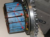
As seen from the photo, the GL-2 has:
51 stator poles ( 51=17X3); and
46 magnet poles (46=23X2).

If 1 magnet pole = 180 electric degree;
then 1 stator pole = 180 * 46/51 = 162 elect deg.

The Hall sensors of this motor is spaced 1.5 stator pole apart which is 162x1.5 = 243 elect deg.

It seems the Hall sensors could be spaced either at 120 elect deg or 240 elect degree apart. Is it correct?
 
I'm not totally clear on how they calculate the electrical angle.
Controllers are typically either 120 deg. or 60 deg. I suppose multiples of either would work out to the same thing.

That looks like a nice motor. What is it?
 
It's a GL2 from Brett (solarbbq)

http://www.users.bigpond.com/solarbbq/GL2.htm
 
Interesting.

I'm sure that thing could take more than 350w.
Higher voltage should be no problem either.

I like the winding configuration. Crystalyte uses overlapping windings (I forget the proper terminology). Each coil goes around 3 poles. This motor has a separate coil for each pole, which reduces the amount of copper in the ends, which don't contribute to output. This should improve the efficiency slightly by comparison.

I'd like to see a wider (torquier) version.
 
fechter said:
I'm not totally clear on how they calculate the electrical angle.
Controllers are typically either 120 deg. or 60 deg. I suppose multiples of either would work out to the same thing.

For the BMC motor:
No of stator poles = 18
No of magnet ploes = 16

Then 1 stator pole = 180 X 16/18 = 160 elect deg
Hall sensors space at 3 stator poles = 160X3 = 480 elect deg

This matches Fecther's saying.
 

Attachments

  • hall_sensors_194.jpg
    hall_sensors_194.jpg
    56.1 KB · Views: 3,400
Hall sensors for 3-phase BLDC motors are to be spaced at 120 elect deg apart.

Let H1 be at 0
Then H2 is placed at 120 elect deg and
H3 at 240 elect deg.

Technically H2 could be placed at (120 + 360m) elect deg and
H3 be at (240 +360n) elect deg.
where m, n are any integers 0,1,2,3 ....... and -1,-2, -3....


Most motors ( like GL2) use m=n=0 for 120 elect deg spacing
Some motors (like BMC) use m=1 and n=-2 for 480 elect deg spacing.
 
Back
Top