Max volts for this controler

Thanks For the reply Dr. K

"DrkAngel wrote"
Typically, running Diodes in parallel produces "unreliable" results.
Interesting that you got things working.

Yes for the most part it required constant monitoring and adjusting...
The hotter the diodes were/more current draw, the more voltage drop there was across them.
Originally I thought it would be more consistent.

Likely, small gauge wire is responsible for your noticed voltage sag.
MeanWell S-150-5 at 5V 30A would want 10AWG-ga-gauge copper wire to maintain 30 amp throughput ... without noticeable voltage sag.

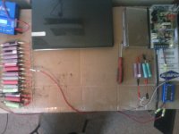
Interesting I used 12 gauge wire and I thought it was rated to 30A...wire never got hot unless it was by the diodes.
Isn't there always a voltage drop when current passes through a diode? (Side affect of turning diode on)
I have 10 gauge but was going to save that for the battery because my 1000W motor will draw 45A max, and 10 gauge is rated to 45A right?

Remember though ...
Without modding, MeanWell S-150-5 is current limited at ~40A, (at 4.15V x 40A = 166w), will allow entire unit to overheat, ... so setting for final voltage and using lighter gauge charging leads ... might be a good thing?

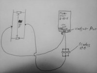
In the beginning of the charge the voltage on the meanwell terminals was well over 5v, with a voltage drop ~1v across the diodes in the positive lead. On precharged cells ~4.05-4.1v.
By the end of the charge voltage on meanwell terminals was ~4.42v and at the end of the charging leads hooked to cells there was 4.15v. (which at this point the Amp draw was very little.)

But, don't be afraid to mod the MeanWell!

Okay! :lol:... This would be great! I want it to be set at 30A max output.


I have read the article...

Swapping voltage pot from 1k to 2k will allow voltage adjustment from ~3.75V to 5.4V.
Or the R25 mods ... upping R25 value 1k would change oem voltage adjustment to a more accurate 3.75V - 4.5V.

Okay I want to do the R25 mod...So just solder in another 1K resistor in series with the R25. (prob use a 30w soldering iron?)

Sorry, I have not figured the values for the current mods yet. - Had to rig a <5V 50A digital meter

This is my main concern with modding the meanwell. I don't have a proper amp meter for reading the current. (I should just buy a inductive lead amp meter multi meter.) But I really don't need anymore current then 30A so soldering another resistor in series to the R33 or R38 would be ideal....

Or wait lowering the ohms makes for lower Amps right? Idk It's hard to tell from the article...

To lower the ohm value would I cut both resistors out and solder in one lower ohm resistor in parallel to both resistor pos. and neg points? Or would I have to keep the R33 and R38 circuits separate and solder in one lower resistor on each resistor pos. and neg. points? Or would I just have to mess with one of them?

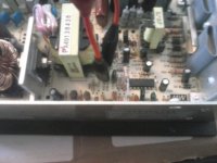
What are the values of the R33 and R38 in ohms? I just took the cover off I guess I could check them. Still don't know which way to go...


P.S. I doesn't say in the S-150-5 wiki article to solder in a 1k resistor in series to the R25 resistor. It said in series to the factory pot.

Also it is my under standing that voltage "sag" and voltage "drop" are two different things. Voltage sag is battery/power supply voltage before applying a load compared to battery/power supply voltage after initially applying a load. Voltage drop is how much voltage drops when crossing a load or connection or length of wire. Right? NBD I know what you mean.

Thanks again on all your advice! :D
 
what made you put diodes in the charging circuit. is that what you are talking about? you should not have diodes in any of the charging circuits or in the discharging circuits. but i cannot follow anything here it is so confusing. can you just draw a diagram on a napkin and take a picture so we know what the circuit looks like?
 
diggler said:
Swapping voltage pot from 1k to 2k will allow voltage adjustment from ~3.75V to 5.4V.
Or the R25 mods ... upping R25 value 1k would change oem voltage adjustment to a more accurate 3.75V - 4.5V.

Okay I want to do the R25 mod...So just solder in another 1K resistor in series with the R25. (prob use a 30w soldering iron?)

Sorry, I have not figured the values for the current mods yet. - Had to rig a <5V 50A digital meter

This is my main concern with modding the meanwell. I don't have a proper amp meter for reading the current. (I should just buy a inductive lead amp meter multi meter.) But I really don't need anymore current then 30A so soldering another resistor in series to the R33 or R38 would be ideal....

Or wait lowering the ohms makes for lower Amps right? Idk It's hard to tell from the article...

Thanks again on all your advice! :D
R25 mod (voltage range shift - lower) requires de-soldering 1 leg of the R25 resister and adding a 1k resister in series.
R33 mod (current mod) involves adding a resister in parallel, just add a resistor to the legs of R33 & R38.

I will try to test and write up the necessary values.
Made a 4V 50A capable gauge, just gotta rig enough cells for a 30A+ drain ... hoping to get it done today.

Added external battery to -
New Low Price
Digital 60V/100A Balance Voltage Power Analyzer Watt Meter Tool - $12.59+
Looks to be a great little tool! No Balance Function!

Necessary to attach dedicated battery

I will add results to the ES Wiki page and leave a not here.
 
MeanWell S-150-5

Got the MeanWell S-150-5 R33 and R25 values figured for you.
Not all the possible values, but should cover your needs handily.
 
dnmun said:
what made you put diodes in the charging circuit. is that what you are talking about? you should not have diodes in any of the charging circuits or in the discharging circuits. but i cannot follow anything here it is so confusing. can you just draw a diagram on a napkin and take a picture so we know what the circuit looks like?

I just thought it would be easier then doing the meanwell mods. You see the meanwell was putting out 5+v and on the other side of the diodes I was getting 4.15v. Then as cells were close to full charge there was ~4.5v on meanwell and 4.15v on the other side of diodes. (voltage drop across diodes was higher with more current passing through them.) It was working until I tried charging cells that were 3.65v. Too much current for the diodes to handle.

I'm going to do the proper meanwell mods now though. This way I wont have to contently monitor voltage at the ends of the leads and adjust meanwell pot accordingly.

Sorry for the sloppy drawing. Hope it's clear enough to get a basic idea of what I was doing.
 

Attachments

  • CAM00091 (2).jpg
    CAM00091 (2).jpg
    249 KB · Views: 2,441
DrkAngel said:
R25 mod (voltage range shift - lower) requires de-soldering 1 leg of the R25 resister and adding a 1k resister in series.
R33 mod (current mod) involves adding a resister in parallel, just add a resistor to the legs of R33 & R38.

I will try to test and write up the necessary values.
Made a 4V 50A capable gauge, just gotta rig enough cells for a 30A+ drain ... hoping to get it done today.

Added external battery to -
New Low Price
Digital 60V/100A Balance Voltage Power Analyzer Watt Meter Tool - $12.59+
Looks to be a great little tool! No Balance Function!

Necessary to attach dedicated battery

I will add results to the ES Wiki page and leave a not here.

Okay great!

:lol: I feel stupid I forgot I had already bought that same exact watt meter!

Well off to the store to get a 1k resistor, 2k pot, some solder wick and a plug for the watt meter.

Thanks again for the quick replies!
 
okay got the meanwell mods done...

All they had were 1/2k resistors and 5k pots at radio shack. So I soldered 2 resistors in series for the R25 mod and hooked the 5k pot in parallel to the R33 & R38 resistor.

I wired the watt meter in the charging leads but it didn't turn on! :x

Since it didn't come with any info I looked on ebay for some answers. It sais the min volts are 4. So im charging cells to at least 4v. (they were 3.95)

Also about the three prong plug on the side. Which pin is pos. which is neg. and what's the other one for? And how many volts does the dedicated battery have to be.

I messaged the seller but maybe someone here knows.

Thanks

diggler

O thanks Dr. K for your work on wiki today...

I got the pot set at 1400 ohms and the open circuit voltage at 4.15 so it shouldn't be too many amps if I use it now but just waiting till I can get the watt meter working to be safe...

What was the volts set at when you were doing your tests? You said min so I assume ~4.5v. Unless modded

I know with lower volts there will be more amps but 1400 ohms is 29.6A. So 150/4.15=36.14A. I should be safe.
 
I put a 2k pot at SVR1 and dropped voltage to 3.74V for Amp testing.
3.74V x 40A = 149.6w
Not recommending! ... but I just shorted the leads to get amp readings ... couple seconds.


Any 6V - 12V small DC adapter will work fine - watch for rate of discharge if batteries used.
I used a 2s 18650 (8.2V) battery holder.

3rd leg might be neg-ground also, I did not test.
Check "continuity" with 1st leg, ... if curious?


"Confidence grows with every mod!
Duh ... till you screw up!"
 
Wow everything is working great now! :D
Thanks a lot for all your help. Ill be on the fast track in no time now!
 

Attachments

  • CAM00094.jpg
    CAM00094.jpg
    246.1 KB · Views: 2,429
  • CAM00098.jpg
    CAM00098.jpg
    256.3 KB · Views: 2,429
  • CAM00099 (1).jpg
    CAM00099 (1).jpg
    413.4 KB · Views: 2,429
  • CAM00093.jpg
    CAM00093.jpg
    247.8 KB · Views: 2,429
diggler said:
dnmun said:
what made you put diodes in the charging circuit. is that what you are talking about? you should not have diodes in any of the charging circuits or in the discharging circuits. but i cannot follow anything here it is so confusing. can you just draw a diagram on a napkin and take a picture so we know what the circuit looks like?

I just thought it would be easier then doing the meanwell mods. You see the meanwell was putting out 5+v and on the other side of the diodes I was getting 4.15v. Then as cells were close to full charge there was ~4.5v on meanwell and 4.15v on the other side of diodes. (voltage drop across diodes was higher with more current passing through them.) It was working until I tried charging cells that were 3.65v. Too much current for the diodes to handle.

I'm going to do the proper meanwell mods now though. This way I wont have to contently monitor voltage at the ends of the leads and adjust meanwell pot accordingly.

Sorry for the sloppy drawing. Hope it's clear enough to get a basic idea of what I was doing.

diodes do not have a fixed forward bias. it changes with the current flow through the diode. so your schematic indicates a setup that does not stop the cell from overcharging if you expected the diode to prevent the voltage from climbing to 5V.
 
diodes do not have a fixed forward bias. it changes with the current flow through the diode. so your schematic indicates a setup that does not stop the cell from overcharging if you expected the diode to prevent the voltage from climbing to 5V.


right that's why I had to keep adjusting the voltage on the meanwell.....I mentioned that at least twice....At first there was over 1v drop then at the end of the charge I had the stock meanwell voltage all the way down ~4.42v (I can't remember exactly it go's a little lower the 4.5v) and there was only a 1/4v drop over the diodes due to less current flow. Even with very little current flow there is still a voltage drop.

It doesn't matter now I got the proper mods done
 
okay so I have this kit http://www.ebay.com/itm/281199914680?ssPageName=STRK:MEWNX:IT&_trksid=p3984.m1439.l2649

I have used 60V on it and it works fine go's about 35mph.

I saw this controller http://cgi.ebay.com/ws/eBayISAPI.dll?ViewItem&item=131098947426

I asked them how many volts can it go up to.

All I can get out of them is "you want 48v one or 72v one"

Haha I was trying to get spacifics like what's the max volts for the 48v one and what's the low volts for the 72v one.

My question is can my motor handle 72v?
 
Your motor can handle any voltage. The question is what voltage your controller handle. Most 48V controllers are rated limited by 63V caps. if you want to know how many volts you can use on a controller you need to ask the voltage ratings of the caps and mosfets.
 
thanks for the info but someone ells on here told me that my motor can only handle 72v in burst. He has the same motor, but is that true? If that's the case I'll just run 60v max.(63)

I already ordered it out of panic because it was the last one so I think I got the 48v one.

These guys at the company don't seem to want to tell me anything they just keep saying u want 48v or 72v?

I will try again to ask them what the voltage rating of the caps and mosfets are.

Just incase I get the same response. Is there a way I can find out for myself what the hi and low volt max is on this controller? Or does anybody know?

I'm sorry I don't even know what a cap and a mosfet are or what they look like.

Thanks again to the community of this forum without it I would still be in the dark and probably not cruisin.
 
i can take a 72V motor and burn it up on 24V. I can also take a 24V motor and run it constant for years on 100V. It's not about volts. It's about watts. The controller that came with the kit you listed will be a 30A or less controller and will have 63V caps and 68-75V mosfets in it with an LVC of 42V.If you want to use more than 63V, you need another controller. With the proper controller you could run over 100V. The specs on the controller you listed is for a 48V controller. What caps and fets are inside is a mystery to me, but I pretty much bet they are the standard 63V caps. I don't know why you would want to buy another 48V controller when one comes with the motor kit.
BTW, there are pictures of capacitors (caps) and fets (mosfets) all over this forum, and probably the wiki.
http://endless-sphere.com/w/index.php/Main_Page
 
thanks I'll have to do some more reading.
I wanted to buy this other controller because it is a regenerative breaking controller with cruse control! It's supposed to save 30% of the battery with regen.

I tried asking them what the 48v controller had for caps and mosfets but they said 48v only use 48v 72v only use 72v what one you want?

Which confused me even more because I already bought it and I told them that, and there was no option to pick 48 or 72. So I told them to send the 72v one. I figured go big! I can always set cruse control. We'll see what I get in two weeks.
I would assume the 72v one would be more expensive.
 
The controller that came with your kit probably has regen braking and cruise control too. It's probably just not enabled. But for someone that doesn't know what a cap or fet is, I'm sure that's asking a lot. However, there are people here that have the same kit as you and may have already found out how to enable them.
 
really okay I'm glad I told them 72v then. I think I'll make a separate ebike for speed n pleasure crusin. idk I think I'll put it on a 20" chopper stile ebike probably only 10 ah maybe it'll do burnouts.

yah I didn't even hook up the break switch to my current controller.
But I'm definitely going to enable regen and cruise on my controller. I wasn't very comfortable with just cantilever breaks with 60v and trying to keep the throttle around 20 mph was extremely annoying and jerky. Thanks for letting me know. I had no idea that was possible.

60v should be fast enough for the commuter and keep me out of trouble.
 
okay so this is my controller.http://www.ebay.com/itm/281199914680?ssPageName=STRK:MEWNX:IT&_trksid=p3984.m1439.l2649
I have been looking on here to find out how to enable regen and cruise.
I haven't found anything yet. Just thought id ask so see if anybody knows a good link? thanks
 
if you don't get any responses from people that have that kit and have enabled the features you want, you'll have to open the controller to the board level, take lots of good photos of everthing , post them and see what kind of responses you get from that. Or you can just buy another controller already set up for regen and cruise control for ~$50 that will have the requied wires to enable them. This is one such controller that they will configure the way you want it.
http://www.aliexpress.com/item/Free-Shipping-48V-1000W-45Amax-BLDC-motor-controller-E-bike-brushless-speed-controller-compatible-for-sensor/497637202.html
 
This is such a great link to a awesome controller for my cruiser!

I wont need to hook up a cycle analysis to use all the functions of this controller will I?
I will get one eventually but I don't have one yet, so I'm ordering one with the six wire cycle analysis hookup.

I'm also ordering the LVC's to be 54.15V (for 60V hookup) and 43.32V (for 48V hookup), switchable.
This is so no cell will get below 3.61V. Does this sound like a good Idea? Any thoughts?

I'm also ordering it to be 45A capable and to have the better mosfets installed. (I thing 4110's over 4120's or whatever?)

I want the hi-med-low switch to be set for when I'm hooking up 60V:
;hi-full power (~35mph)
;med-? % of throttle to make it go ~22mph?
;low-? % of throttle to make it go ~15mph?

Does anybody know approximately the right % of throttle for those speeds at 60V with a 1000w watt motor?
Or is all this stuff set with the cycle analysis, idk?

Any thoughts and info will be much appreciated.
Thanks
 
No, you don't need a CA for the controller functions. LVC should be set according to the battery chemistry and size of the battery. For rc lipo, I'd recommend 3.5V per cell. I don't use lifepo4, but if I did, I'd set it to no lower than 2.5V per cell and would probably use 2.7V per cell. Lifepo4 users could probably give you better insight into this. My controller has 15 4410 mosfets and it's been working fine for over 3 years now. 4110' have lower RDSon values but that won't make any real noticable differnce. They do have higher amp ratings though and I'm told produce less heat. They only cost a few cents more, so if you can get hem for a few bucks more total, I'd do it. Full power on 60V nominal should do 35mph easily. A wag for 22mph would be 50% and 35% for 15mph. If you hook up a CA, you can set the speed in it.
 
Cool on another note the other controller came in and I cracked it open and its the 72V one. I was looking at the caps and mosfets, and the caps all say 100V except for one of the smaller ones is 63V and all the tinny ones are less.
Does this mean I can go 100V max on this controller?
Also the fets are 4410's and 15 of them. This probably means less than 45A right?
And should I be carefull or do something to use regen and not burn up the controller and motor? or just not use it? but that's fast!
A must will be two more TA from the dock.
I'm thinking about a 20" or 26" chopper style bike with just a 10Ah battery.
Any body have suggestions on a good enough motor for that and 96V with regen on? Mine is a three faze 1000W is that good enough? I have been reading a lot about the possibility of motor/controller burn up with regen and axils snapping! I don't have crazy hills but good ones and still 96V is fast!


Also just an Idea.. I'm kicking around trying to make it a hybrid.
By putting a nice quiet 4 stroke 49cc engine on it with this set up.
Theoretically I could leave the electrical motor on and use it for breaking and charging the batteries while using the gas motor to puts. Then when I wanted to hall ass I could hit the electric motor throttle!
Also I could go as far as I could with electricity then go in gas limp mode for more endless possible distance.

The only problem is how to hook them both up to the same hub?
Also the gas motor hub gear would have to have it's own freewheel! Right?

Has anybody tried to make a hybrid? Any thoughts?

Ha ha I forgot about human power. That's like a triple hybrid! Might as well put a rocket on it! Go nuts just kidding but seriously?
 
15 4410 fets with 100V caps should be god to 100V. That's exactly what I have and I've been running it at 100.8V for over 2 years now. I've never had a problem using regen. I wouldn't want to ride very fast without it.
 
so for that 48v controller im getting, could I hook a 200w front hub motor up to it also to provide regen braking?
do I need a separate controller to use two hub motors on one bike?
With one controller would both motors always have to propel or is there a way to make the front just for regen?
I'm thinking I need two controllers to pull this off hooked to one battery.
Also is it okay to run a 200w motor with 60V? I'm thinking it is. The motor will only draw what it can handle right? Or with a separate controller I could just have the front H/M/L swithch set on medium or low throttle (if I need to use it in slippery conditions) to drive the front wheel.

And how about a front hub on a 96V set up? Would a 200w motor be good enough for strictly regen and low throttle operation?

Any insight on this whould be much appreciated! thanks
 
Back
Top