adrian_sm
1 MW
Here are some thoughts I have had on maximising the performance of our ebike controllers, by not just focusing on limitting the battery side input power, but more on the motor outputs. Specifically output torque, and power. This can help protect the system components, while maximising performance, and staying as legal as you wish too. Here is what I was thinking ...
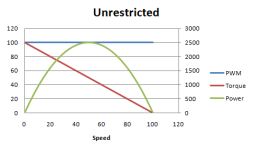
If your controller does not limit current to the motor you would see the motor power, and torque graph look something like this. This is what RC style ESCs typically do.
But most ebike controllers limit the input power via PWMing the phase current up until the motor BEMF limits the power even at full throttle.
This results look something like this.
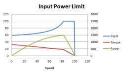
But this has two undesirable effects:
1) the output power prior to the peak is always below the peak.
- So if you are aiming to maximise the output power to a legal limit, you are loosing out.
2) the torque (and phase current) may be higher or lower than desired at low speeds, depending on the current limit.
- Too high and this is hard on mosfets, phase wires, connectors, and drive train components
- Too low and you are loosing out on low end torque, because of your power limit at higher speeds.
Now we can measure the motor speed, and battery current easily enough. And if we assume the throttle % directly relates to the PWM, then we can estimate the phase current, and therefore torque. Source discussion: http://www.endless-sphere.com/forums/viewtopic.php?f=4&t=37964&p=553707&hilit=torque+limit+analyst#p553707
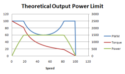
This additional information would allows us to implement theoretical output power limiting, giving us more low end power and torque.
Or implement a torque limit that limits the low end torque, but allows more power in the mid range.
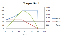
Or even both, resulting in increased mid range power (compared to a normal input power limiting ebike controller), while still keeping the low end torque in check to protect phase wires, mosfets, connectors or drive train components for non-direct drives like my friction drive.
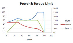
I am currently implementing this scheme and will hopefully document any progress here. The output torque and power will be user-adjustable, making it simple to switch between any of these schemes.
- Adrian
If your controller does not limit current to the motor you would see the motor power, and torque graph look something like this. This is what RC style ESCs typically do.

But most ebike controllers limit the input power via PWMing the phase current up until the motor BEMF limits the power even at full throttle.
This results look something like this.

But this has two undesirable effects:
1) the output power prior to the peak is always below the peak.
- So if you are aiming to maximise the output power to a legal limit, you are loosing out.
2) the torque (and phase current) may be higher or lower than desired at low speeds, depending on the current limit.
- Too high and this is hard on mosfets, phase wires, connectors, and drive train components
- Too low and you are loosing out on low end torque, because of your power limit at higher speeds.
Now we can measure the motor speed, and battery current easily enough. And if we assume the throttle % directly relates to the PWM, then we can estimate the phase current, and therefore torque. Source discussion: http://www.endless-sphere.com/forums/viewtopic.php?f=4&t=37964&p=553707&hilit=torque+limit+analyst#p553707
justin_le said:Torque limit also works best from the perspective of protecting controller mosfets and motor phase wires and connectors. IF the throttle output of the CA is mapped properly and the controller takes the throttle signal as a direct control of the PWM duty cycle, then the CA should be able to estimate the motor current from
Motor Current ~= Battery Current / (Act Throttle Output / Full Throttle Output)
And hence could set up a limit accordingly.
This additional information would allows us to implement theoretical output power limiting, giving us more low end power and torque.

Or implement a torque limit that limits the low end torque, but allows more power in the mid range.

Or even both, resulting in increased mid range power (compared to a normal input power limiting ebike controller), while still keeping the low end torque in check to protect phase wires, mosfets, connectors or drive train components for non-direct drives like my friction drive.

I am currently implementing this scheme and will hopefully document any progress here. The output torque and power will be user-adjustable, making it simple to switch between any of these schemes.
- Adrian

