
DrkAngel
1 GW
MeanWell Mods
MeanWell Mods - S-150-5
MeanWell Mods - S-150-12
MeanWell Mods - S-150-24
MeanWell Mods - S-150-48
MeanWell Mods - S-240-48
MeanWell Mods - S-350-48
See- ES Wiki MeanWell Mods for more
MeanWell S-150-48

Specs:
*Mean Well S-150-48
*150w max continuous output
*48V - adjustable from 43V - 53V
* (40.14 - 55.42 measured)
*(V - V As tested on 1 sample)
*3.2A max continuous output@48V -
*48V x 3.2A = 153.6W
*No fan - Open grid shell - convection cooling
Factory Specs
Problem:
*Rated at 3.2A, but will surge-sustain much higher, burning components
Solution:
*Restrict the amp output -
*The "R33" resister is the key to regulating amperage.
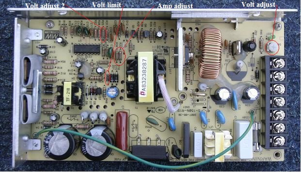
S-150-xx component locations

*For testing purposes, I soldered 2 wires of a 2s balance plug to the ends of the R33 resister.
*Then plugged a multi-turn 2K Pot (potentiometer) into the balance connector.
*Then I lowered the voltage to minimum and applied "load".
*Removing and measuring the pot's ohms at each 1/2 amp mark.
*(Pot must be removed to measure! "In circuit" it is laid parallel with 2 other resisters.)
Restricting Current (Amps):
*4.2A = OEM (386ohm)
*A = 10K
*A = 8.1K
*A = 4.6K
*A = 3.3K
*A = 2K
*A = 1.65K
*A = 1.3K
*A = 1K
*A = .81K
*A = .63K
Wider Amp adjustment:
*Disconnect, or remove R33 & R38.
*Replace with adjustable "pot"
*Amps ........ Ohms
*1A ... from ... 92ohms
*2A ... from ... 185ohms
*3A ... from ... 277ohms
*4A ... from ... 370ohms
*4.2A ... from ... 386ohms
*5A ... from ... 460ohms
*5.4A ... from ... 500ohms
Widening the voltage range:
*By changing the value of the Voltage pot, I was able to lower the output range substantially.
*1K = 43 - 53V (oem)
*2K = 31.1 - 53V
Adjusting voltage below 29.2V resulted in a "fault" (required power off - power on to reset)
*As I will demonstrate later, there can be great advantages to lower voltages.
Note! The higher value pots (100K etc) only allow a very "coarse" adjustment at the high voltage end. Harder to fine adjust.
Lowering Voltage
*Lowering voltage could take advantage of higher amperage.
*Without removing components, amperage is regulated below ~4.2Amps.
*R33, combined with it's neighbor R38, have a measured resistance of ~865ohms.
*Removing both and replacing with a 2K pot allowed me to produce a
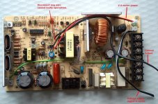
Detail View
2004 - 08 - 27

Raising Voltage?
*R25 Mod
*The voltage adjustment pot (SVR1)limits voltage adjustment between 43V - 53V. It is possible to adjust voltage lower, but not higher, using a "larger" than 1K pot.
*However, the SVR1 pot is "in series" with the R25 resister.
*Altering the value of the R25 will shift the entire voltage range higher or lower
*I charted values for lower voltage values but only briefly tested higher voltages using by replacing R25 with a 2K pot. (S-24-150 data) >> I was able to push voltage to ~34V with <1.5k ohm before the power supply "faulted", 33V seemed sustainable. (Should be capable of near 60V)
R25 Mods - Lower Voltages
*Seems to fault near 24V, low voltage limit.
*Secondary voltage regulation seems to be regulated by component ZD1, (Zener Diode #1), reputably a ?V value component.
*This model has 63V caps ... a fairly strict limitation!
150 Watt!
*To be safe and effective, amperage should be adjusted as voltage is altered.
*Volts x Amps = Watts
*Watts should equal, or be slightly below, 150 watts.
*54.4V x 2.75A = 150W
*52V x 2.88A = 150W
*50V x 3A = 150W
*48V x 3.125A = 150W
*46V x 3.26A = 150W
*44V x 3.40A = 150W
*42V x 3.57A = 150W
*40V x 3.75A = 150W
*38V x 3.94A = 150W
*36V x 4.16A = 150W
*34V x 4.41A = 150W
*32V x 4.68A = 150W
*30V x 5A = 150W
*Yeah ... I'm gonna try pushing everything to the limits ... and then a little further!
(Will test to confirm)
Component Locations
In Series
----
*"In series" is when the negative of one power supply is run through the positive of another - combining their voltages.
Important!
*When run in "series" the DC "negative" must be isolated from the 110AC negative ... on all but the primary unit!. Otherwise, the DC positive from the primary unit will "short" through the AC negative on the secondary unit.
Tested model demonstrated proper electrical isolation - many S-150's haven't
Confirm no continuity between "Ground" and DC negative!
'''The negatives are usually connected through the "ground"."
*3 points of "ground" to remove.
*The external ground - terminal 3.
*The green wire, at F1 near terminal 3.
*The bottom of the circuit board, under screw hole next to fuse. (Cut circuit traces, or insulate with ... fiber, or nylon, washer and screw?)
* The case can be "properly" grounded by connecting the AC ground wire to the removed green wire directly.
MeanWell Mods
S-150-5
S-150-12
S-150-24
S-150-48
S-240-48
S-350-48
MeanWell Mods - S-150-5
MeanWell Mods - S-150-12
MeanWell Mods - S-150-24
MeanWell Mods - S-150-48
MeanWell Mods - S-240-48
MeanWell Mods - S-350-48
See- ES Wiki MeanWell Mods for more
MeanWell S-150-48
Specs:
*Mean Well S-150-48
*150w max continuous output
*48V - adjustable from 43V - 53V
* (40.14 - 55.42 measured)
*(V - V As tested on 1 sample)
*3.2A max continuous output@48V -
*48V x 3.2A = 153.6W
*No fan - Open grid shell - convection cooling
Factory Specs
Problem:
*Rated at 3.2A, but will surge-sustain much higher, burning components
Solution:
*Restrict the amp output -
*The "R33" resister is the key to regulating amperage.
S-150-xx component locations
*For testing purposes, I soldered 2 wires of a 2s balance plug to the ends of the R33 resister.
*Then plugged a multi-turn 2K Pot (potentiometer) into the balance connector.
*Then I lowered the voltage to minimum and applied "load".
*Removing and measuring the pot's ohms at each 1/2 amp mark.
*(Pot must be removed to measure! "In circuit" it is laid parallel with 2 other resisters.)
Restricting Current (Amps):
*4.2A = OEM (386ohm)
*A = 10K
*A = 8.1K
*A = 4.6K
*A = 3.3K
*A = 2K
*A = 1.65K
*A = 1.3K
*A = 1K
*A = .81K
*A = .63K
Wider Amp adjustment:
*Disconnect, or remove R33 & R38.
*Replace with adjustable "pot"
*Amps ........ Ohms
*1A ... from ... 92ohms
*2A ... from ... 185ohms
*3A ... from ... 277ohms
*4A ... from ... 370ohms
*4.2A ... from ... 386ohms
*5A ... from ... 460ohms
*5.4A ... from ... 500ohms
Widening the voltage range:
*By changing the value of the Voltage pot, I was able to lower the output range substantially.
*1K = 43 - 53V (oem)
*2K = 31.1 - 53V
Adjusting voltage below 29.2V resulted in a "fault" (required power off - power on to reset)
*As I will demonstrate later, there can be great advantages to lower voltages.
Note! The higher value pots (100K etc) only allow a very "coarse" adjustment at the high voltage end. Harder to fine adjust.
Lowering Voltage
*Lowering voltage could take advantage of higher amperage.
*Without removing components, amperage is regulated below ~4.2Amps.
*R33, combined with it's neighbor R38, have a measured resistance of ~865ohms.
*Removing both and replacing with a 2K pot allowed me to produce a
Detail View
2004 - 08 - 27
Raising Voltage?
*R25 Mod
*The voltage adjustment pot (SVR1)limits voltage adjustment between 43V - 53V. It is possible to adjust voltage lower, but not higher, using a "larger" than 1K pot.
*However, the SVR1 pot is "in series" with the R25 resister.
*Altering the value of the R25 will shift the entire voltage range higher or lower
*I charted values for lower voltage values but only briefly tested higher voltages using by replacing R25 with a 2K pot. (S-24-150 data) >> I was able to push voltage to ~34V with <1.5k ohm before the power supply "faulted", 33V seemed sustainable. (Should be capable of near 60V)
R25 Mods - Lower Voltages
*Seems to fault near 24V, low voltage limit.
*Secondary voltage regulation seems to be regulated by component ZD1, (Zener Diode #1), reputably a ?V value component.
*This model has 63V caps ... a fairly strict limitation!
150 Watt!
*To be safe and effective, amperage should be adjusted as voltage is altered.
*Volts x Amps = Watts
*Watts should equal, or be slightly below, 150 watts.
*54.4V x 2.75A = 150W
*52V x 2.88A = 150W
*50V x 3A = 150W
*48V x 3.125A = 150W
*46V x 3.26A = 150W
*44V x 3.40A = 150W
*42V x 3.57A = 150W
*40V x 3.75A = 150W
*38V x 3.94A = 150W
*36V x 4.16A = 150W
*34V x 4.41A = 150W
*32V x 4.68A = 150W
*30V x 5A = 150W
*Yeah ... I'm gonna try pushing everything to the limits ... and then a little further!
(Will test to confirm)
Component Locations
In Series
----
*"In series" is when the negative of one power supply is run through the positive of another - combining their voltages.
Important!
*When run in "series" the DC "negative" must be isolated from the 110AC negative ... on all but the primary unit!. Otherwise, the DC positive from the primary unit will "short" through the AC negative on the secondary unit.
Tested model demonstrated proper electrical isolation - many S-150's haven't
Confirm no continuity between "Ground" and DC negative!
'''The negatives are usually connected through the "ground"."
*3 points of "ground" to remove.
*The external ground - terminal 3.
*The green wire, at F1 near terminal 3.
*The bottom of the circuit board, under screw hole next to fuse. (Cut circuit traces, or insulate with ... fiber, or nylon, washer and screw?)
* The case can be "properly" grounded by connecting the AC ground wire to the removed green wire directly.
MeanWell Mods
S-150-5
S-150-12
S-150-24
S-150-48
S-240-48
S-350-48

")


