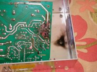
Well, my trusty old S-350-48 bit the dust. It was working fine, then suddenly started going into a reduced output mode where I could only get about 300mA out of it. I noticed that if I tapped on the frame, I could get a blip of normal output. While trying to track down the loose connection, it suddenly went BANG and expelled the contents of the main switching transistor.
I was in the market for a replacement when hagerty1 offered to send me a new MeanWell USP-225-48 for testing.
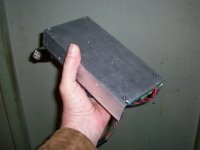
The USP-225 has no fan. The frame is an extruded aluminum channel with beefy 4.5mm thick heat spreaders on the sides.
It measures about 4" wide and 8" long.
View attachment 9
The back side is solid with only a pair of threaded holes for attaching to a bracket.
Here's a link to the datasheet:
http://www.mouser.com/ds/2/260/USP-225-spec-34541.pdf
Out of the box, the voltage adjustment range was 40.0V to 57.5V.
For my pack (either a 16s A123 or 14s Lipo), I wanted about 59V. The secondary over voltage protection circuit kicks in around 60V and the output caps are rated for 63V, so tweaking it up to 59V should be OK.
The voltage adjustment is a resistor divider that's compared to a 2.5v reference. After poking around and doing a little math, I found that if I place a 68K resistor across R129, the adjustment range was now 40V to 59.3V. This is just right, as turning the pot all the way up won't quite trigger the secondary protection circuit.
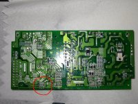
R129 is a tiny little surface mount part on the bottom of the board. Removing the board is fairly easy; unscrew the heat sink, which is one piece, and the 4 mounting screws on the corners of the board.
R129 is located in this area:
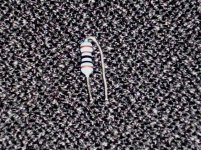
Here's a close-up showing the 68K resistor installed:
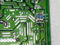
Another way to install a resistor across the chip resistor is to bend it into a 'U' shape and solder it across. After soldering, place heat shrink or some kind of insulation around it to prevent the legs from touching other parts on the board.
CURRENT LIMITER:
The stock current limit is rated at 4.7A. At this level, the supply will overheat fairly quickly. Some way to lower it is needed.
The current is sensed by a shunt resistor and compared to a reference voltage. We can tweak the reference voltage to lower the current limit. The easiest way to do this is to lower the value of R140-142. R140, R141 and R142 are all in parallel on the board. It looks like they install all of them, then snip out one or two to trim the current to spec. On mine, R140 was snipped out. The nominal value of the trio is 100 ohms. By lowering the resistance, we can lower the current limit.
By adding a 1K - 2K mulit-turn trim pot across R140, the current can be adjusted over the desired range.
Alternately, you could remove all 3 resistors and install a 100 ohm trim pot.
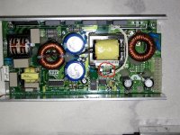
R140-142 are located on the top in this general area:
Here's a close-up:
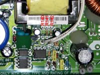
You could attach a pair of wires to the ends of the resistor on the board and extend them to a pot located elsewhere or you could attach the pot directly to the board. I was lazy and went straight to the board. I cleared out the holes from the missing R140 spot and soldered a trim pot directly onto the board. I bent over the unused leg on the pot and covered it with heat shrink to prevent shorts.
Here's how it looks:
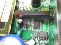
I drilled a small hole in the heat sink that lines up with the adjustment screw on the pot to allow adjustment.
I use mine with one of those cheap volt/amp meters that also measures amp-hours. Rather than trying to find a connector to fit the one on the board, I soldered wires directly to the bottom of the board (easy).
Here's how it looks:
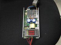
Initially I ran it at 3.5A but found it got pretty hot. By sitting the supply on it's edge rather than flat, the dissipation is much better and it can run at a higher current. I finally settled on about 2.5A to keep things cool.
To find the adjustment points, I reverse engineered the key parts of the regulator circuit.
WARNING: schematic is not entirely correct. For reference only.
View attachment 1

I was in the market for a replacement when hagerty1 offered to send me a new MeanWell USP-225-48 for testing.
The USP-225 has no fan. The frame is an extruded aluminum channel with beefy 4.5mm thick heat spreaders on the sides.
It measures about 4" wide and 8" long.
View attachment 9
The back side is solid with only a pair of threaded holes for attaching to a bracket.

Here's a link to the datasheet:
http://www.mouser.com/ds/2/260/USP-225-spec-34541.pdf
Out of the box, the voltage adjustment range was 40.0V to 57.5V.
For my pack (either a 16s A123 or 14s Lipo), I wanted about 59V. The secondary over voltage protection circuit kicks in around 60V and the output caps are rated for 63V, so tweaking it up to 59V should be OK.
The voltage adjustment is a resistor divider that's compared to a 2.5v reference. After poking around and doing a little math, I found that if I place a 68K resistor across R129, the adjustment range was now 40V to 59.3V. This is just right, as turning the pot all the way up won't quite trigger the secondary protection circuit.
R129 is a tiny little surface mount part on the bottom of the board. Removing the board is fairly easy; unscrew the heat sink, which is one piece, and the 4 mounting screws on the corners of the board.
R129 is located in this area:

Here's a close-up showing the 68K resistor installed:

Another way to install a resistor across the chip resistor is to bend it into a 'U' shape and solder it across. After soldering, place heat shrink or some kind of insulation around it to prevent the legs from touching other parts on the board.

CURRENT LIMITER:
The stock current limit is rated at 4.7A. At this level, the supply will overheat fairly quickly. Some way to lower it is needed.
The current is sensed by a shunt resistor and compared to a reference voltage. We can tweak the reference voltage to lower the current limit. The easiest way to do this is to lower the value of R140-142. R140, R141 and R142 are all in parallel on the board. It looks like they install all of them, then snip out one or two to trim the current to spec. On mine, R140 was snipped out. The nominal value of the trio is 100 ohms. By lowering the resistance, we can lower the current limit.
By adding a 1K - 2K mulit-turn trim pot across R140, the current can be adjusted over the desired range.
Alternately, you could remove all 3 resistors and install a 100 ohm trim pot.
R140-142 are located on the top in this general area:

Here's a close-up:

You could attach a pair of wires to the ends of the resistor on the board and extend them to a pot located elsewhere or you could attach the pot directly to the board. I was lazy and went straight to the board. I cleared out the holes from the missing R140 spot and soldered a trim pot directly onto the board. I bent over the unused leg on the pot and covered it with heat shrink to prevent shorts.
Here's how it looks:

I drilled a small hole in the heat sink that lines up with the adjustment screw on the pot to allow adjustment.
I use mine with one of those cheap volt/amp meters that also measures amp-hours. Rather than trying to find a connector to fit the one on the board, I soldered wires directly to the bottom of the board (easy).
Here's how it looks:

Initially I ran it at 3.5A but found it got pretty hot. By sitting the supply on it's edge rather than flat, the dissipation is much better and it can run at a higher current. I finally settled on about 2.5A to keep things cool.
To find the adjustment points, I reverse engineered the key parts of the regulator circuit.
WARNING: schematic is not entirely correct. For reference only.
View attachment 1

