Mk 2 KMX the Viper second eKMX

hi all
last night fitted the metal gears in the mk2 puma, boy can the circlips fly when you don't want them to, I nearly lost one of the gear circlips when it flew off the pliers and it took me 5 mins to hunt it down.

I have named the plate the three gears are on as the gear assembly to avoid confusion in the following post.

As for the actual gear change as knoxie and several others have said a gear puller was used, being in the UK I went to a internet firm called screwfix who have started to open retail stores and there is one on my local industrial estate, the cost was less than £10 ($20) for a set comprising of a 6 inch,a 4 inch and a 2 inch. when I got the set home and offered them up to the puma none of the set would fit, not to be dashed I took the 6 inch appart and just offered up the arms to the puma this fitted but would I be able to remove the gear assembly I had had no luck with the mk1 puma in a previous attempt.

So first things first and sorry no pictures :oops: out with the trusty drill vice to hold the puma still while it was worked on we all remember the case of the local bike shop my puma getting a new block and then me getting credit from fechter for my "marster class" in how to make a new hub motor cable. So the vice clamps the flats and allows the cable to come out undammaged, the case of the puma is removed prior to being clamped in the vice cable down gears up. There is a circlip just above the gear assembly check at this point and find the "wavy washer", it will either be in the case of the puma flange side or on the axel somewhere above the circlip this washer is inportant it protects the ballrace from rubbing on the circlip remove both "wavy washer"and circlip and put to one side. next take the gear puller and place an arm hook under the edge of the assembly plate if you are lucky you will not have needed to take your gear puller to bits even though I had (and this was because the hook was too deep I could of cut a bit off with a dremel but I thought I would try without first so once the arms were in place I pushed the arms apart at the same time thus by lever action lifting the gear assembly, it lifted with no problems at all in less than a minute I had the gear assembly seperate in my hand put on one side look on the axel and find the "key and remove and put with the circlip and other "small bits". Remove motor from the vice and put on one side take the gear assembly and place in the vice gears up so you can get at the circlips holding on the gears these circlips don't have holes just curves hence the 5 minute search I mentioned before, as each clip is taken off store with the small bits, once the three gear circlips are off thats it all change take out the metal gears and swop them for the plastic gears already there store the plastic gears just in case,replace gear circlips then remove gear assembly from vice and put motor back in it's place. Take the "key" and put it back in the axel slide the gear assembly back onto the axel lining the key in the axel up with the notch in the gear assembly the push the assembly home remember gears face down, if you encounter resisance then cogs may not be meshing correctly as you push down on the gear assembly turn the gears they will find a place to go into then stop turning and just push till the gear assembly hs been pushed on fully at that point the grove that the last circlip fits into should become visable, then just put the circlip on and put the "wavy washer" on top of it.
Thats it now put the motor back in the case make sure the "wavy washer is in the right place next to the gear assembly retaining circlip when you put the motor into the flange side of the case make sure the motor is pushed home as with the gear assembly the gears may not mesh as you start to put the motor in twist the motor until the the motor is in then put the lid on and screw down.

The way the motor is designed you could change the gears with a disk brake on ,a freewheel , 7 speed block or connectors for the cable left in place and still do it there may be a few be mor complications I don't know I havn't tried.
 
nice.

you'll have to let me know how it affects noise but im betting it wont be too bad :)
you know what im going to say dont you? :) PICS!!
sounds like you have done a real sweet job on that motor Geoff - mines currently at steves workshop so im particularly interested to see whats involved and how it differs from mine with the gear setup if at all?
I'll ask steve if he has time to take a few snaps so we can compare - i think paul said to beef up the phase for 50a so we will need to take a look for sure.
keep us updated and get some snaps if you can - all you all back together now and ready for test?


Cheers


D
 
hi all
knoxie and a few others who run pumas at 72v how do they hold up, I have a temp. sensor fitted in the puma so I can keep an eye on its temp as I am going along.
I have stopped doing active work for 2 weeks because of injury my right index finger was not allowed near any of the power tools in my work shop. The finger has recovered enough now that I can carry on so the first job will be a second set of mockup torque arms, once they are done I can get the stainless steel ones made then I can get on to the next major step putting the puma in the rim, I want to take the puma to the place the torque arms are being made to check they fit so I don't want the rim there as well.

Anyone know which sort of grease I should use on the metal gears, auto thick grease or more of the white that came in the puma if the white where do I get it?
 
Hi Geoff,

good to hear the hand is healed nicely :)
i think the white grease is for plastic, teflon grease or something - maybe you would need somethingmore specific to the metal gears? I'm sure paul or Steve would know better?
Do you have a nice clear pic of your motor? i ask as i have bought a second pums now 8) i have the 320 rpm from Mark and im not sure what o expect yet as it went straight to Joz for some prepping and painting.
I'm not sure if we are doing a phase wire change but i have decided to hold off on the metal gears until my nylon ones wear - steve has had no problem with the gears on his 320 so we'll just have to see how that goes.
If you do have some pics please post up geoff - i'd also like to see how the disk clearence and cassette looks on yoursout of curiosity? does your motor have 10mm flats but 14mm threads?????
Hopefully i will get my bike back over the next couple of weeks, im really looking forward to trying the new motor at 50a 66v - i have kept my original puma laced into the twenty's for backup and i may even have a blast on them at 50a too or make a 2nd bike :roll:


Cheers

D
 
Hi D
the mk2 puma has 15mm axel with 10mm flats the max gears is is a 7 speed block on standard 135 dropouts, the disk brake disk you will have to tell me about, I saw the thread on the motor and phoned mark to ask if a disk would fit he said no to start with but when pressed he said that the disk you have on your mk1 puma will fit but because of no spares he has no more so I could not have one, but you can :evil:

been on to the enginers who were going to make the torque arm, they said lazer cutting would be cheaper and more precise so I have been on to firms to get costing and find tolarences,one said they would make a mockup out of thin leftover send it through to me and I can test it on the puma axel.

That desided on I laced up the puma into the combat rim this evening, I'll post some pictures in the morning.
 
yes please do geoff,

if your having your arms made maybe you could get them to make you a disk adapter too?
i can give you the measurements off mine maybe? - i'll post up some pics of my new motor once i get my bike back, sounds like we have the same model.


Cheers


D
 
hi all
yesterday I contacted a lazer cutter and asked him to cut a "washer" template to see if the lazer cutting would work or wheather I would have to build in tolarence, the job was simple hole for a mk2 puma which I though was a 15mm axel with 10 mm flats put it on an offcut of another job I was asked how big do I want in so I said a disk 25mm dia. he sent them free and they arrived today .
mk2 puma lazer test.jpg
the flats fit perfect but I made a mistake the axel is 14 mm not 15 mm as I have always said so far in this thread I am sorry my mistake.
below are 2 pictures of the puma with a disk on the axel.

View attachment 2

test disk on axel side view.jpg


The puma mk2 is now laced into the rim and I have a picture below

rear hub laced in rim.jpg
there are no connectors on as yet they will be put on when the torque arms are in place as they will not fit over the torque arm hole the wires have been crimped and are ready.
tomorrow the tyre goes on and the puma is fitted to the kmx with the mockup torque arms to find the final shape of the drive side torque arm and the shape of the sharks fin type device to protect the frame from chain damage.
 
hi all
now I have the templates back from the lazer cutter so I know the quality of their work I started back to work on the design of the torque arm.while I was shapeing the dropout in the computer to lay the torque arm design over I found out somthing, a normal rear axal is 10mm dia and fits snug in a dropout see below
rear dropout non-driveside 2.jpg

but the puma mk2 axel is 14mm with 10mm flats so although it fits it is anything but a good fit
rear dropout driveside no gear hanger puma mk2 axelno fillit.jpg

while I was doing the CAD work on the torque arm I had an idea it came from the picture below
cad of axel hole.jpg

I phoned up the lazer cutter and asked if they could cut out a small shape out the quarter moon at the end of the axel hole, I recived some test samples out of thin aluminium which I glued together this has the effect of changing the dropout so it is a snug fit to the puma axel see below.
rear dropout driveside no gear hanger puma mk2 axel quarter moon fillit.jpg
 
hi all
the torque arm build of this beast is nearly over well stage one is, I desided to do the torque armes in two stages first the non-drive side with an aluminium drive side torque arm to find out what must be removed to miss the chain and swing arm, the non-drive torque arm will be taking the strain even when finnished that arm will be the stronger of the two.

So what will be made up is as follows the torque arm, the torque arm template and my "quarter moon" fillits.
the zip file contains a dxf file of the non-drive side torque arm, the file contains 3 images on the left at the bottom is for a lazer cutter the one above is a mirror image colour coded for identifying, the blue V are centre points for the holes in the arm, the greem circle is the hole for the bolt to attach the arm to the chainstay,the red circle is for my trailer attachment normaly this is put on the axel of a cyle but I wanted it to be independent, the magenta arc is the shape the dropout takes and where the "quarter moon" fill-it goes, the top two circles bolt onto the frame.
The arm on the right is one that was made in 3d so if you have a cad pacage that will take the file and can do 3D then set to 3D and look at a vertual torque arm in the computer.
 
The whole torque arm thing still bugs me. The motor should come with a built-in torque arm like a Heinzmann so we don't have to fabricate things. :evil:

Imagine using a super large wrench to twist the axle hard enough to make the bike do a wheelie with a rider on board. That's about how much torque the axle can produce. I'd be a bit concerned about putting any holes in the sides of the dropouts since the holes will weaken the metal in the area where the stress is the highest. On steel dropouts it's not as critical, but aluminum scares me. The washers should be pretty thick, at least 4-5mm I'd guess, and made of very hard material. I guess the holes for the small screws will need to be countersunk or counterbored so the screw heads don't stick out.

As long as the axle bolts are very tight, and stay tight, the combination of the plates and friction should keep things from moving.

In your pic of the left side dropout, I can see little teeth marks around where the axle goes. These are presumably left behind by some kind of washer. If the shoulder of the axle that presses against the inside of the dropout had the same kind of teeth, it would bite into the dropout and help prevent movement.
 
fechter said:
The whole torque arm thing still bugs me. The motor should come with a built-in torque arm like a Heinzmann so we don't have to fabricate things. :evil:

Imagine using a super large wrench to twist the axle hard enough to make the bike do a wheelie with a rider on board. That's about how much torque the axle can produce. I'd be a bit concerned about putting any holes in the sides of the dropouts since the holes will weaken the metal in the area where the stress is the highest. On steel dropouts it's not as critical, but aluminum scares me. The washers should be pretty thick, at least 4-5mm I'd guess, and made of very hard material. I guess the holes for the small screws will need to be countersunk or counterbored so the screw heads don't stick out.

As long as the axle bolts are very tight, and stay tight, the combination of the plates and friction should keep things from moving.

In your pic of the left side dropout, I can see little teeth marks around where the axle goes. These are presumably left behind by some kind of washer. If the shoulder of the axle that presses against the inside of the dropout had the same kind of teeth, it would bite into the dropout and help prevent movement.
the 3 m3 holes near the dropout on the drive side are used by KMX to attach a replacable gear hanger see below
replacable gear hanger.jpg
the dropouts are steel 5mm thick, I've taken on board what you said and droped the m3 holes from the torque arm to add strength, I have desided on a 30mm dia exclusion zone from the centre of the axel hole I will post a picture of the design I have come up with done in cad.
 
hi all
over the past few days I have tranfered the rear dropout area into a 3D cad package most is acurate what is not does not matter for what I was doing .
I have used this to make the torque arms and to check wheather they will fit the only thing I could not check on was the interaction between the swing arm and the drive side side torque arm, so I have had to have a mockup cut by the lazer cutters so to cover myself I have had a mockup of the non-drive side arm cut just to check.

now have a close look at the dropouts on the kmx as posted by me if you have been looking at the torque arm thread I started up I said that what was required was the angle between the dropout flats and under the chainstay, well on a cycle with only one arm that is no problem but with two torque arms I found more difficultys, the angles are slightly diffrent,also as I have said before that the curve on dropouts is 10mm dia but I need a 14mm dia curve, the answer was new dropouts thanks to fecter, deecanio and jozzer for sowing the seeds that caused me to come up with them.
first a cad picture of the drive side, the loud colours are for clarity
drive side torque arm spacer and new dropout.jpg
originaly I was goin to attach the arm with the 3 holes round the axel with a reses so the head of the screw was not prowd but fechter warned me of holes too close to an axel so I did away with the idea but still had the artwork in the computer, jozzer had told me how the KMX dropouts were not over hub motor friendly so it was not just me. deecanio spured me on to not give up on trying to work out a way to put a drive-side torque arm on the kmx so since it would not work next to the gear hanger I thought of a spacer to move the arm outboard a bit but while I was doing that why not fix the problem of the dropout shape giving me the 70 degree that one of the flats is at.
I first chose 8mm as a spacer thickness but whenI had added up all of the bits that would be put onto the axel I founf there would not be enough so I have redused the spacer to 4mm and done away with the washer just left the spring washer presing against the torque arm I think the stainless steel can take it.
Once I had done this I Thought the sensible thing to do would be to do the same sort of thing on the other dropout so I cut the botom off the torque arm and extended the flats and came up with what is below, this will be made out of 4mm stainless steel.
non-drive side torque arm spacer and new dropout.jpg
 
Geoff, can you make those torque arms closed around the axle instead of open?

They would be MUCH stronger.
 
Mark_A_W said:
Geoff, can you make those torque arms closed around the axle instead of open?

They would be MUCH stronger.
they are not the torque arms the torque arms are in yellow/orange in the pictures below
drive side in cad web.jpg
non-drive side in cad web.jpg
they are a combination of spacers and replacement dropouts for the kmx to make the dropouts ideal for the hub motor it has nothing to do with torque arms any more than the frame of a cycle has.
 
Oh, sorry, yes they look fine.
 
hi all
one good thing about the mk2 puma is the length of axel that is past the frame stop point, you get 35mm to play about with on both sides if you use the 135 mm dropout spacer so for me that means with a 5mm frame 30 mm of axel thread sticking out on both sides, this is why I was able to put so much steel on the drive side axel and still get a nut on.
 
hi all
had a word with the cutters and they are cutting the spacer/ dropout modifier over the weekend (snowed under with work) I am getting a left and right torque arm cut out of thin aluminium to make sure I have the mesurments right for the arms the new dropouts are correct the cost for these 4 bits is going to be about £12.
Once the new dropouts are on I will be able to start to put the rear end together putting the puma in chain on and testing things out on a rolling road type thing I bought which is two steel rollers on bb races in a steel frame bought for motor bikes,it is a bit like the things used to test cars, the results are a system that gives me the ability to sit on the trike pedal or use the motor or both and observe without going anywhere I can keep all my tools at hand.
As soon as I get the parts through I will post them.
 
hi all
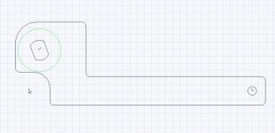
here is a drawing of the drive side torque arm the mouse cursor is where the rear deralliur is attached to the frame of the viper, the grid was 1mm
the axel hole is of course 14mm with 10mm flats, the hole at the far end of the arm is 6 mm
drive side torque arm web.jpg
the green circle is 30mm dia from the centre of the axel
 
Hi all
I got some post this morning
first batch from the cutter web.jpg
the small peices at the top are the dropout spacers/reshaperes, the lower two with white covering are torque arm templates.
the templates are made of 2mm aluminium.
the spacers are made of stainless steel 304 4mm thick and should have have registration marks on for me to drill holes but due to the fact that aluminium will not take marks like this because it is too shiny the cutters asked if the marks could be removed from the aluminium I said this was ok I could use another method for marking the aluminium, unfotunatly the marks for the spacers were deleated as well, I had a word with the cutter and if marking by hand fails new spacers will be cut.

I am now gowing to drill the bits ready to put on the viper.
 
hi all
this is the drive side dropout spacer after I had drilled it, I have put one of the m3 torx bolts I will be using on the kmx. The holes were first drilled out 3 mm for the bolts I then had to deal with counterboaring the holes so the hed was flush with the surface of the spacer, the head is just over 2mm deap and 6mm in diameter my drill has a mesuring device on it so I had no problem in drilling the counterboar. Because I was working with stainless steel I bought some dewalt drill bits they are stronger bits and over 5mm come with twin head size a tap size half the full size of the drill so for the 6 mm bit a 3mm pilot hole is cut this worked perfectly to cut the steel when I set the drill to its slowest speed.
drilled driveside dropout.jpg
 
Back
Top