zombiess
10 MW
So I've been continuing to experiment with the Xie Chang based controllers and have a strong affinity for the IRFB4115 FETs because of being able to safely run 100V battery packs.
Tonight I did some testing and tried out one of the EB318 controllers with matched FETs that I built and will be selling. This is not a for sale thread so don't talk about it or PM me about it (there will be a thread in the for sale section when I'm ready), I'm just mentioning it because it has caused me to look closely into these controllers and how to make them survive better. Good news is I have succeeded in getting one of my IRFB4115 18 FET controllers to run at 100A battery, 135A phase. Bad news is I blew it up first running it at 115A battery, 180A phase (yes, I was stupid and actually tried it this high for my maiden voyage... made it 50 ft :lol: )
Little back story to explain why I started off so high. I received a blown to hell (literally had exploded FETs) EB318 controller board in a set of 3 broken ones I purchased from someone on here to keep around for spare parts. I looked at it and said... I can fix that. 7 hours of work later, rebuilding traces and killing myself working with SMD parts that had evaporated traces... it lived. I did not want to waste IRFB4115 FETs on it in case it didn't work so I used some IRFB4110's that I had left over. I had just enough to build 6 closely matched sets of three. Since then I have been flogging the crap out of this controller using a 75V 18AH nanotech pack on one of the hardest to drive motors I know of, my 18.6Kv Cromotor. It has an inductance of 30uH which is less than half of what the controller killing Crystalyte 5302's had.
Anyways, I build all my controllers the same way. Polished heat sink bars (compliments of my wife), individual bergquist insulators, properly applied thermal paste between heat sink bar and case, matched FETs, beefed up traces, good low esr electrylytic caps and then I add on pulse rated polypropylene low esr caps at each end of the power rail and one between each phase for a total of 4. These 18 FET controllers use 0.22uF caps in addition to the 0.1uF caps that come stock.
So this IRFB4110 controller I built from literal scrap has been running 150A battery, 170A phase at 75V power this controller killing Cromotor for around 100 miles now without any issues. It even runs much cooler than I thought it would (at least externally, I'm lacking the internal probe at the moment). Max speed is limited to 99% so it is always in PWM on the high side. I scoped the low side of the controllers and the EB318 controllers only do block commutation on the low side, just like the EB2xx boards do. The EB3xx boards appear to have some way to measure and limit phase current from what I can tell so far but haven't been able to prove it yet.
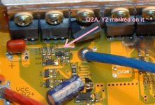
So since I am doing a batch of 20 IRFB4115 18 FET controllers I need to know what they are capable of handling so I can rate them for people. Since I had such great luck with my IRFB4110 controller I decided to start off high on the 4115 controller for shits and giggles just to see what happens. I have a thermocouple installed to monitor the high side FET temperature directly on the body of the FETs. Settings were 115A battery, 180A phase. It worked fine on low (33%), dead stop, hitting it hard, no problems. Then I tried 99% and felt that familiar problem of something just went wrong. Took it inside and ripped it apart. Low side FETs of Phase A were dead. Not exploded, just dead with one showing a tiny pin hole and cracked case but no flames. Other 2 looked ok but were toast. Unfortunately it also took out the low side driver NPN transistor as well. Replaced everything and got it back up and running. Used my brain this time and turned the settings down. 100A battery, 134A phase. Battery at 74V and away I went. Watched the current spike to 105A then hold 98-102A during acceleration and taper off to 85A once I got up to around 48MPH. Top speed was GPS'd at 53MPH. I rode it WOT for just over 1/2 a mile and stopped under a street light to read my temp meter. It said 84C was the max recorded. Turned around and went back the opposite way for about 3/4 of a mile non stop. Max temp 100C. Did another pass after a 30 sec break to check the meter and when I stopped again I managed a max temp of 102C. I sat for about a min, checked the external temp of the controller with my hand which was quite warm, much warmer than the IRFB4110 controller runs at +140 amps. Made another 3/4 mile pass just to see if the controller would blow up or heat up more but it appears to have leveled off temperature wise and when I stopped the temp started dropping from 84C pretty quickly. Called it quits at this point because I had faith in the controller. Unfortunately for some reason I no longer have regen working after it blew up. When I hit regen it engages for a second, then cuts out like the FETs popped the first time. Need to trouble shoot this or just disable it all together since everything else is good.
I roll the bike back inside and watch the internal temp drop down to around 55C and level off there. The external case temp had risen even more at this point, quite hot, even burned my finger on one of the heat sink screws when I touched it. From there it took about 3-4 mins before the case cooled down and was just luke warm.
A while ago I had hypothesized that the IRFB4115 would run similarly in performance to the IRFB4110 based on switching loss calculations, but run hotter under WOT conditions because of it's higher RDSon value of 11mOhm vs 4.5mOhm for the 4110's. Turns out I was correct, but it ran a lot hotter than I though it would vs the IRFB4110. I will be installing a temp probe in my IRFB4110 controller in the same location an run the same settings in it to gather temperature data from it so I can compare the two to see just how much difference there really is.
I will also be switching motors back to a regular 9.6Kv Cromotor in a 16" wheel which has an inductance of 120uH so it's much easier to drive to see what happens with the temperatures of the FETs and my ability to run higher currents based on the temps. I believe they will run a bit cooler based on my old Lyen IRFB4115 controller that I have done similar mods too as well. It has survived 105A battery, 135A phase with a Cromotor in a 20.5" diameter tire at 125V and the FETs did not get as warm as they did in this controller (I have a thermocouple on the high side FETs in it as well, but it also has some additional heat sinking from me tying the tabs together with a copper buss bar so it's not a true 1:1 comparison).
Anyways, at this point I feel pretty confident saying IRFB4114 FETs, when matched, can sustain 35A for each one in parallel (so 3 can do 105A) for bursts of 30 seconds. For continuous use it is probably best to derate them to around 20-25A each depending on your ability to cool and keep the temps below 80C. The IRFB4110's appear to be able to handle around 50A each for 30 sec bursts and I would probably limit them to 30-36A each when paralleled for a more continuous type application.
Please note that these FETs are all Miller plateau matched so they have really close turn on times. They are within -/+ 5% of each other which is critical to keeping them alive. Yes I know we have all see people run crazy amps through controllers at their absolute max voltage ratings. You are of course perfectly free to do that, but don't complain if you blow it up. These numbers I'm posting are from my own research, but I figured there would be some interest by others on here. Also keep in mind that the motor I am running is VERY hard to drive for this type of controller and the typical eBike hub motor is exponentially easier to drive due to having much higher inductance.
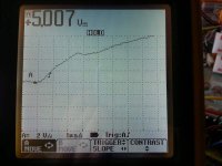
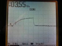
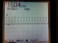
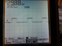
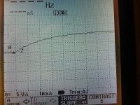
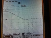
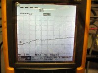
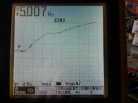
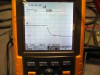
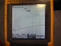
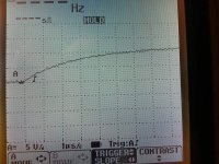
I scoped out the low/high gate drive on this controller and will post the scope pictures tomorrow for those who are interested in seeing the EB3xx drive setup. I need to compare it to the EB2xx drives to see if it's any better.
My keeping the high side at 99% PWM is an attempt to reduce the chance of blowing the high side FETs as they are typically the ones that pop in most controllers, but tonight with my low side going boom due to me going WOT from a low speed at 99% throttle I am going to try setting them at 100% throttle (after looking at the switching times) to see if they live and hopefully run cooler.
I'll be posting more info as I gather it. Scope pics should be up tomorrow.


