This post is about an experiment to monitor motor temperature using the motor axle instead of the windings. The idea is to get useful monitoring information without motor disassembly and pulling a new wire bundle. In this case monitoring is done with a conventional NTC 10K thermistor driving a CA V3 to get both temperature readout and power-rollback to prevent overheating. A simple digital thermometer with probe will work nicely as well. Although my particular installation was done using a drill press, it looks possible to make a little jig so the mod can be done with a hand power drill without dismounting the wheel from the bike.
OVERVIEW: The idea is simply to bore the solid side of the axle deep enough to position a sensor in the axle but under the stator web so that it gets a fairly direct exposure to heat conduction from the windings/stator. This will work best with low to moderate powered motors of smaller diameter so the heat path is short and the temperature differential between windings and stator/axle will not be too large.
Before we get to How, here's a couple of plots of Analogger data for two trips made with the rig:
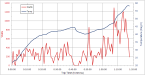
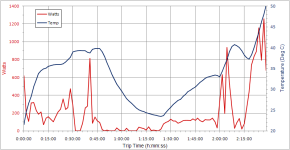
For my purposes, the results are very good, giving a moderately large temperature range for good resolution, pretty fast response to heat buildup, and allowing the use of the CA V3 temp rollback at the higher temp ranges. In general, the temperature readings are what I would expect at the windings except the values are reduced and lag the actual power changes by a minute or two (check the horizontal time scale for wattage changes and the accompanying temp change).
HOW-TO: Frankly, there's not much to say. Drill a 1/8" hole and stick in a sensor - but here's the long form:
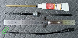
After replacing a hall sensor last summer, I clamped up the motor in the press and shot a hole in the axle. The end of the axle already had a detent for a gear puller so centering was easy. The depth of the hole meant I had to pull the bit every 1/8" to 3/16" of depth to clear chips from the drill flutes once they were below the face of the axle. Unfortunately, I only had a standard jobber length bit and could only drill about 2". So, I just mounted the wheel up and later ordered a long 1/8" bit from Amazon (Bosch BL2635 Black Oxide Drill Bit, 1/8-Inch by 6-Inch). I used the longer bit in a hand-held drill to sink the hole another 1/2" or so, using the existing 2" hole as a guide. I used 'CRC Thread Tapping Cutting Oil Aerosol' with a long thin red nozzle/tube to shoot oil foam to the hole bottom.
Unfortunately, I didn't think of doing this while the motor was apart and I could make some measurements, so I was conservative in the depth to avoid drilling into the wire bundle or gear cluster keyway. The hole is deep enough to get past the major heat radiating components - dropout and motor side - and is just slightly inside the motor. I figured the depth was good enough for a test and it turned out to work fine. I used a drill collar to set the drill depth - optional but handy.
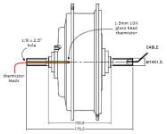
The axle was notched using a dremel with a worn down (smaller diameter) fiber cutting wheel and the sharp edges dressed with a small rotary burr. The idea was to get the relatively delicate wiring protected from crashing through trailside plant growth. Unfortunately, I later realized I should have slotted it deeper so the detent would be unobstructed for gear puller use, but I'll fix that up on a future motor pull. Notching and the last bit of drilling were done with motor on the bike.
The CA V3 is calibrated for a 10K NTC thermistor with a beta of 3900. Any beta in the 3800-4000 range is fine - this just determines the accuracy at the high end. A few degrees one way or the other isn't going to hurt since we are just setting a rule-of-thumb temperature limit anyway. Beta is usually specified with two temperatures 25degC and something like 50degC or 85degC and can be viewed as the slope of the temperature/resistance correction curve where the thermistor is calibrated to give 10K resistance at 25degC. So - a beta of 4050 is 'outside spec' but still workable for this application although it will be off by a few degrees at high temps. Here's some typical thermistors:
These all work about the same - I used the little glass one because it was only 1.5mm or so and required only a small hole in the axle. I spliced it onto some 24 gauge hookup wire with a JST2 connector so I could easily dismount the wheel. A bit of heat shrink about 2.25" long made the assembly rigid enough to stuff into the hole.
To improve the thermal path to the sensor, I used some cheapie Radio Shack silicone heat sink compound (no need to waste the expensive stuff for this application). This turned out to be a good choice because it came in a terrible unthreaded tube with a wacky break-off cap. This worked great because the soft plastic mouth of the tube made it easy to jam in a short length of 1/8" brass tube from the hobby shop. The tube was shoved to the bottom of the drilled hole and a goodly blob of compound injected in place into which the thermistor could be plunged.
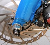
The sensor is plugged up to the CA V3. I presently have (Temp->ThrshTemp, Temp->MaxTemp) set to (58,68) degC which means that when the temp reaches 58 degC the CA starts limiting the current linearly until it reaches zero current at 68 degC. Works great!


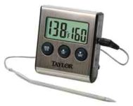
This should work equally well using any of the digital thermometers mentioned in other threads. Units like the one below have a little stainless tube lightly crimped over the wiring - you can easily uncrimp it and expose the tiny temp sensor bead at the end of the wiring.
THOUGHTS: The only real deterrent to doing this installation without a drill press is the chance of the deep hole wandering off the axle centerline. A way to drill this by hand with reasonable accuracy might be to fab up a little reusable screw-on axle drill guide - this could be drilled with the motor still on the bike. Perhaps just thread a lug nut (long with lots of threads) or metric coupler nut onto the axle end, then thread in a 1" long section cut off a metric bolt that is center-drilled 1/8". Lop off a bolt the same size/threading as the axle - a common axle size is M14x1.5 (your mileage may vary). For little widgets like this, I like to go to an auto machine shop (yellowpages.com: "Auto Machine Shop" near "<city, state>") - these are nuts&bolts places where you can walk up to the counter with no drawings and just tell them what you want. They would probably bore a bolt section for $10 or less.
Anyhow - I'm very pleased with the results. The actual installation was very easy with low risk and no bike down-time. I tried monitoring the axle stub directly, but this approach gives much improved range and response time for little effort. Although this is not as responsive as the preferred method of directly monitoring the windings, it's working out great for my bike and riding situation.
Special thanks to Kepler for posting about axle temp monitoring in the CA V3 thread and getting me thinking about this.
As expected, I found other posts about axle temps in the past - here's one or two by dogman.
- CAVEAT: This is NOT an effective technique for general motor temp monitoring for obvious reasons, but it seems to work for moderate powered builds where the primary heat difficulty is slower heat buildup from prolonged higher wattage running. The approach responds too slowly to effectively monitor sharp temp increases from suddenly dumping megawatts of waste heat either from low rpm loading (steep hill climb) or from a high powered motor/controller. Certain riding styles can reasonably push any motor to a sharp temp increase that can cause damage before this approach would detect the temp increase. 'Nuff said.
OVERVIEW: The idea is simply to bore the solid side of the axle deep enough to position a sensor in the axle but under the stator web so that it gets a fairly direct exposure to heat conduction from the windings/stator. This will work best with low to moderate powered motors of smaller diameter so the heat path is short and the temperature differential between windings and stator/axle will not be too large.
Before we get to How, here's a couple of plots of Analogger data for two trips made with the rig:
- Note: The bike has two identical BMC V2S motors and a single CA V3 with external shunt feeding both controllers - temp monitoring is done only on the front motor. The recorded Analogger wattage was divided by two for the purpose of graphing a single motor wattage. There were many thousands of data points - the data was grouped into 100 bins and each bin averaged to a single data point (typically a minute or more) to clean up the plots - max wattage was often significantly higher during any averaged period but only briefly applied:


For my purposes, the results are very good, giving a moderately large temperature range for good resolution, pretty fast response to heat buildup, and allowing the use of the CA V3 temp rollback at the higher temp ranges. In general, the temperature readings are what I would expect at the windings except the values are reduced and lag the actual power changes by a minute or two (check the horizontal time scale for wattage changes and the accompanying temp change).
HOW-TO: Frankly, there's not much to say. Drill a 1/8" hole and stick in a sensor - but here's the long form:
After replacing a hall sensor last summer, I clamped up the motor in the press and shot a hole in the axle. The end of the axle already had a detent for a gear puller so centering was easy. The depth of the hole meant I had to pull the bit every 1/8" to 3/16" of depth to clear chips from the drill flutes once they were below the face of the axle. Unfortunately, I only had a standard jobber length bit and could only drill about 2". So, I just mounted the wheel up and later ordered a long 1/8" bit from Amazon (Bosch BL2635 Black Oxide Drill Bit, 1/8-Inch by 6-Inch). I used the longer bit in a hand-held drill to sink the hole another 1/2" or so, using the existing 2" hole as a guide. I used 'CRC Thread Tapping Cutting Oil Aerosol' with a long thin red nozzle/tube to shoot oil foam to the hole bottom.
Unfortunately, I didn't think of doing this while the motor was apart and I could make some measurements, so I was conservative in the depth to avoid drilling into the wire bundle or gear cluster keyway. The hole is deep enough to get past the major heat radiating components - dropout and motor side - and is just slightly inside the motor. I figured the depth was good enough for a test and it turned out to work fine. I used a drill collar to set the drill depth - optional but handy.

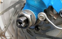
The axle was notched using a dremel with a worn down (smaller diameter) fiber cutting wheel and the sharp edges dressed with a small rotary burr. The idea was to get the relatively delicate wiring protected from crashing through trailside plant growth. Unfortunately, I later realized I should have slotted it deeper so the detent would be unobstructed for gear puller use, but I'll fix that up on a future motor pull. Notching and the last bit of drilling were done with motor on the bike.

The CA V3 is calibrated for a 10K NTC thermistor with a beta of 3900. Any beta in the 3800-4000 range is fine - this just determines the accuracy at the high end. A few degrees one way or the other isn't going to hurt since we are just setting a rule-of-thumb temperature limit anyway. Beta is usually specified with two temperatures 25degC and something like 50degC or 85degC and can be viewed as the slope of the temperature/resistance correction curve where the thermistor is calibrated to give 10K resistance at 25degC. So - a beta of 4050 is 'outside spec' but still workable for this application although it will be off by a few degrees at high temps. Here's some typical thermistors:
These all work about the same - I used the little glass one because it was only 1.5mm or so and required only a small hole in the axle. I spliced it onto some 24 gauge hookup wire with a JST2 connector so I could easily dismount the wheel. A bit of heat shrink about 2.25" long made the assembly rigid enough to stuff into the hole.
To improve the thermal path to the sensor, I used some cheapie Radio Shack silicone heat sink compound (no need to waste the expensive stuff for this application). This turned out to be a good choice because it came in a terrible unthreaded tube with a wacky break-off cap. This worked great because the soft plastic mouth of the tube made it easy to jam in a short length of 1/8" brass tube from the hobby shop. The tube was shoved to the bottom of the drilled hole and a goodly blob of compound injected in place into which the thermistor could be plunged.

- The drilled hole was cleared of chips by inserting the tube from the aerosol cutting oil to the bottom and shooting off some foam. The oil foam swept out the chips.
- This was followed by a similar injection of brake cleaner to degrease the hole (using the standard thin tube applicator that comes with the cleaner).
- Next the heat compound was put in the bottom and the thermistor was inserted in about 1/2" short of the bottom.
- The heatshrink/wiring was coated with a blob of Liquid Lectric tape and the shoved home to bottom the sensor in the hole.
- The leads were folded into the notch and zip-tied to the axle.

The sensor is plugged up to the CA V3. I presently have (Temp->ThrshTemp, Temp->MaxTemp) set to (58,68) degC which means that when the temp reaches 58 degC the CA starts limiting the current linearly until it reaches zero current at 68 degC. Works great!
- EDIT - later changed range to 70degC-85degC.
This should work equally well using any of the digital thermometers mentioned in other threads. Units like the one below have a little stainless tube lightly crimped over the wiring - you can easily uncrimp it and expose the tiny temp sensor bead at the end of the wiring.

THOUGHTS: The only real deterrent to doing this installation without a drill press is the chance of the deep hole wandering off the axle centerline. A way to drill this by hand with reasonable accuracy might be to fab up a little reusable screw-on axle drill guide - this could be drilled with the motor still on the bike. Perhaps just thread a lug nut (long with lots of threads) or metric coupler nut onto the axle end, then thread in a 1" long section cut off a metric bolt that is center-drilled 1/8". Lop off a bolt the same size/threading as the axle - a common axle size is M14x1.5 (your mileage may vary). For little widgets like this, I like to go to an auto machine shop (yellowpages.com: "Auto Machine Shop" near "<city, state>") - these are nuts&bolts places where you can walk up to the counter with no drawings and just tell them what you want. They would probably bore a bolt section for $10 or less.
Anyhow - I'm very pleased with the results. The actual installation was very easy with low risk and no bike down-time. I tried monitoring the axle stub directly, but this approach gives much improved range and response time for little effort. Although this is not as responsive as the preferred method of directly monitoring the windings, it's working out great for my bike and riding situation.
Special thanks to Kepler for posting about axle temp monitoring in the CA V3 thread and getting me thinking about this.
As expected, I found other posts about axle temps in the past - here's one or two by dogman.

