motor waveform symmetry

Lebowski

10 MW
Joined
Jun 27, 2011
Messages
3,412
Location
beautiful Zurich, Switzerland
OK advanced motor question. Lets say the back emf wavefom can be written as

V_emf = A1 cos (w*t) + A3 cos (3*w*t + phi)

this value phi, does it happen that it is something else than either 0 or pi ? I don't think
so but would like to hear from people in the know...

(phi=0 or pi means the positive or negative half of the waveform is symmetrical
(left-right) upon itself. This is the case for for instance trapezoidal waveforms with
rising and falling edges with the same slope. Not however for sawtooth shape
waveforms. But I don't think motors have back-emf like that, correct ? )
 
Lebowski said:
salty9 said:
Would the back emf wave form be similar to the regen wave form?

It's the waveform the motor makes when you use it as a generator...
The wave form the motor makes always looks the same the power added by the controller may make it look different but that from the controller.

Lebowski I don't think any motors make sawtooth waveforms I would believe if they did it would be from a pour design. IE stator tooth relation to the magnet size would be wrong or something like that.
 
A friend of mine once told me, and I think it makes sense, that the best waveform to control a motor has the same shape as the one it produces as a generator.
 
Hence sinusoidal controllers. :mrgreen:
 
Lebowski ~

the waveform will be symmetrical *provided* the pole shoes + magnets are electrically/geometrically symmetrical about their own midplanes.

It is not uncommon in "primary"-directional motors to have some form of bias on either the stator shoe, or the rotor pole that favors one direction of rotation (e.g. by "tilting" magnets/poles, or decreasing the airgap on the "incoming" side, etc). (I think single-phase motor designs even 'require' this).
 

Attachments

  • back_emf.JPG
    back_emf.JPG
    30.9 KB · Views: 1,351
all that said -- if you're *measuring* back-emf on a motor (spinning the shaft open-circuit, no controller) and seeing some funny asymmetry, there's probably some coil short or cross-wiring at interconnects . . .

or if seeing it only "in-circuit" with a driver, there may be funny stuff going on with the controller.
 
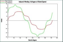
The motor EMF of my 80100 looks similar to the attached curve. It contains a frequency 7x higher than the fundamental. Probably because the motor has 7 pole pairs. The curve is roughly described:

V_EMF = sin(w*t) - 0,07*sin(7*w*t)

which I believe is the same as:
V_EMF = sin(w*t) + 0,07*sin(7*w*t + pi)

Some trivia:
I measured this a few month ago. I don't have a digital scope, so I used my PC soundcard to sample the waveform. It looked different in the PC compared to the scope though, so I figured that it had to do with some filter at the "line in" input. When I did this spice model, and put a 20Hz high pass filter in it, I got the same waveform as I measured with the PC.

EDIT: Oh, I realized that your question was whether phi could be something else than 0 or pi. I originally read it as if the question was whether it could be pi. Well, if you have some filter in the measuring system, like I had with the PC, it could look like phi is pi/2 or similar, like the blue curve below. I don't know if the actual motor could have phi=pi/2. I have only measured EMF on two BLDC motors, and one of them had phi=0, and the other phi=pi.

file.php
 

Attachments

  • motor_emf.PNG
    motor_emf.PNG
    38.2 KB · Views: 646
from your formula it should be called a 'cos' wave..........not a sin wave! You could call it a complex cos wave, how about a ccwave?
 
Who are you talking to?
It doesn't matter if I write cos or sin. It's just a matter of preference.
 
Back
Top